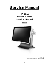
Bematech SB1015W User manual

Category
POS terminals
Type
User manual

This manual is also suitable for

SB1015 All-in-one Touch POS Terminal
USER MANUAL
1
Table of Contents
1 Introduction ..........................................................................................2
1.1 Safety Information ........................................................................................ 2
1.2 Electromagnetic compatibility statement ................................................. 3
2 Overview ................................................................................................ 4
2.1 Features ........................................................................................................... 4
2.2 Appearances .................................................................................................... 4
2.3 Outline Dimensions ....................................................................................... 4
2.4 Rear panel I/O connectors ............................................................................. 5
3 Setup and Driver Installation ..............................................................6
3.1 Motherboard Connectors .............................................................................. 6
3.2 Motherboard Headers .................................................................................... 7
3.3 Header pin assignment .................................................................................. 7
3.5 Motherboard BIOS settings ......................................................................... 14
3.6 Touch screen driver installation .................................................................. 19
4 Hardware Installation ....................................................................... 24
4.1 Magnetic Script Reader (MSR) Installation * ............................................ 24
4.2 LCD Rear Display installation * ................................................................... 25
4.3 SATA Hard Disk Installation ........................................................................ 26
5 Troubleshooting ................................................................................. 27
6 Specifications .................................................................................... 29
2
1 Introduction
Thank you for purchasing the SB1015 all-in-one touch POS terminal. The SB1015
offers highly enhanced features, with easy connection to various optional devices
for optimal performance. This easy-to-use POS terminal is designed to help you
enhance your business flexibility and offer superior customer experience.
Bematech is committed to continuously improve product quality and provide better
after-sales service. In order to take full advantage of our devices, we strongly
recommend that you take the time to read this manual before setting up software
solution.
Note: Information in this manual may change without prior notice.
1.1 Safety Information
Before plug in the product, please make sure the power you provide meets
the power requirements (such as voltage, frequency); Make sure the ground
terminal of the power outlet is working properly.
To avoid electric shocks, disconnect the power cord from the electrical outlet
before relocating the system.
Lightning may damage this product. During lightning storms, unplug the
network cable, power cable and any other connections.
Turn off power before connecting any devices (except USB devices) to the
terminal.
Do not attempt to open the chassis. You may be hurt by electric shock. For
service, call your place of purchase.
Do not spill liquid on the terminal. Do not place any objects into the
ventilation holes of this product. It may cause short-circuit of the internal
components and cause a fire or electric shock.
After the terminal is stored below temperature of 10 ° C, please place it in
room temperature (10-35 ° C) in the original packing for at least two hours to
allow the terminal to restore to room temperature before operation. This is
to avoid condensation that might cause electrical damage.
Keep the terminal clean, dry, and away from dust, moisture and direct
sunlight.
Do not use harsh chemicals or strong cleaning solvents to clean the monitor
3
screen. Wipe it clean with a soft terry cloth applied with a mild solution
Do not share the same power outlet with high-power electrical appliances;
keep distance from high level magnetic interference.
Do not the use sharp pointed objects to work with the touch screen to avoid
damage to the screen.
When the following occurs:
Liquid gets inside the POS terminal;
Accidental physical damage;
The power cord or plug is damaged;
POS terminal produces a burning smell;
Immediately disconnect the power supply, unplug the power cord, and contact a
qualified service technician.
1.2 Electromagnetic compatibility statement
FCC NOTICE
This device complies with Part 15 of FCC Rules. Operations are subject to the
following two conditions: (1) this device may not cause harmful interference,
and (2) this device must accept any interference received, including interference
that may cause undesired operation.
EUROPEAN COMMUNITY (CE) MARK OF CONFORMITY
This product is in conformity with the protection requirements of EU Council
Directive 89/336/EEC on the approximation of the laws of the Member States
relating to electromagnetic compatibility. Bematech / Logic Controls cannot
accept responsibility for any failure to satisfy the protection requirements
resulting from a non-recommended modification of the product. This product
has been tested and found to comply with the limits for Class A Information
Technology Equipment according to CISPR 22 / European Standard EN 55022.
The limits for Class A equipment were derived for commercial and industrial
environments to provide reasonable protection against interference with
licensed communication equipment.
4
2 Overview
2.1 Features
True-flat no-bezel 15" touch monitor with LED backlight display
Fanless design
High performance Intel quad core celeron processor J1900
Support DDR3L SO-DIMM 1066/1333 MHz up to 8GB
Stable and robust mechanical design
Easy to change or replace hard disk drive
Optional integrated 8" customer LCD, 2x20 VFD and 3-track MSR.
2.2 Appearances
2.3 Outline Dimensions
5
2.4 Rear panel I/O connectors
At the rear panel of the SB1015 is a row of external I/O device connectors
detailed as follows:
Port
Name
Function
DC-in 12V Power
Connector
Connect compatible power adapter to provide power
supply for the system.
USB 2.0 Port
Connect USB keyboard, mouse or other devices
compatible with USB specification.
USB 3.0 Port
Connect USB keyboard, mouse or other devices
compatible with USB specification. USB 3.0 ports
supports up to 5Gbps data transfer rate.
VGA Port
Connect second display device that support VGA
specification.
Serial Port
Connect external devices that supports serial
communications interface.
RJ-45 LAN Port
This connector is standard RJ-45 LAN jack for
Network connection.
Line-Out
Connector
Connect external speaker, earphones, etc for system
audio output.
Power Switch
For user to boot/shutdown system.
VGA Port
Line-OUT
DC12V
Power-in
Connector
USB 2.0 Ports
RJ-45 LAN Port
USB 3.0 Port
COM1 Port
USB 2.0 Ports
COM2 Port
COM3 Port
POWER
SWITCH
6
3 Setup and Driver Installation
3.1 Motherboard Connectors
ATX12V
Power Connector
DDR3L
SODIMM Slot
VGA Port
Intel CPU
PCI Express x1 Slot
LVDS Header
Front Panel
Audio Header
Front Panel Header
DC12V
Power-in
Connector
M-SATA
Connector
LVDS
Inverter
SATAII Port
(SATA1)
USB 2.0 Port
Over USB 3.0 Port
USB 2.0 Ports
RJ-45 LAN Port
Line-Out
Connector
SATA Hard Disk
Power-Out Connector
USB 2.0 Header
Mini-PCIE
Connector
PS2 KB/MS Header
VGA Port Header
SPEAKCON1
SPEAKCON2
JP2
TX-RXCOM2 Header
COM1 Port
HDMI Port Header
GPIO Header
HDMI_SPDIF Header
Parallel Port Header
Serial Port Headers
(COM6/5/4/3/2)
7
3.2 Motherboard Headers
Header
Name
Description
FP_AUDIO1
Front Panel Audio Header
9-pin Block
SPEAK_CON1
Left Speaker Header
2-pin Block
SPEAK_CON2
Right Speaker Header
2-pin Block
SPDIF
HDMI_SPDIF Header
2-pin Block
COM2/3/4/5/6
Serial Port Header X 5
9-pin Block
TX-RXCOM2
RS422/RS485 Header
4-pin Block
JW_FP
Front Panel Header(PWR LED/ HD LED/Power
Button /Reset)
9-pin Block
GPIO
GPIO Header
10-pin block
F_USB1
USB 2.0 Port Header
9-pin Block
PS2KBMS
PS2 Keyboard & Mouse Header
6-pin Block
LPT1
Parallel Port Header
25-pin Block
HDMI
HDMI Port Header
20-pin Block
CPUFAN1
CPUFAN Header
4-pin Block
SYSFAN1
SYSFAN Header
3-pin Block
VGA1
VGA Port Header
12-pin Block
JP2
LVDS Panel Brightness Adjustment Header
2-pin Block
INVERTER
LVDS Inverter
6-pin Block
LVDS
LVDS Header
30-pin Block
3.3 Header pin assignment
(1) FP_AUDIO1 (9-pin): Line-Out, MIC-In Header
Pin 1
LINEOUT2-L
LINEOUT2-R
SENSE-FB
AUDIO-GND
LINE2-JD
AUDIO-JD
2
KEY
MIC2-L
MIC2-JD
MIC2-R
SENSE1-RE
TURN
8
(2) SPEAK_CON1 (2-pin)/ SPEAK_CON 2 (2-pin): Speaker Headers
SPKL+
SPEAK_CON1
Header
SPKL-
SPEAK_CON2
Header
Pin1
Pin1
SPKL+
SPKL-
(3) SPDIF (2-pin): HDMI_SPDIF Out Header
Pin1
SPDIF
GND
(4) COM2/3/4/5/6 (9-Pin): Serial Port Headers
DCD
Pin1
6
SIN
SOUT
DTR
GND
DSR
RTS
CTS
RI
(5) TX-RXCOM2 (4-Pin): RS422/485 Header
TXDP
Pin 1
RXDP
RXDN
TXDN
4
3
2
*Notice: User needs to go to BIOS to set ‘Transmission Mode Select’ as [RS422/RS485]
for COM2 as well (refer to Page 34).
(6) JW-FP (9-pin): Front Panel Header
VCC
HDDLED-
GND
RSTSW
PWRLED-
PWRLED+
GND
Pin 1
2
PWRBTN
HDDLED+
9
(7) GPIO (10-pin): GPIO Header
Pin 1
2
GPIO_30
2
GPIO_32
GPIO_34
GPIO_36
GND
GPIO_31
GPIO_33
GPIO_35
GPIO_37
VCC
(8) F_USB1 (9-pin): USB 2.0 Port Header
2
VCC
-DATA
-DATA
NC
GND
+DATA
GND
VCC
+DATA
Pin 1
(9) PS2KBMS (6-pin): PS/2 Keyboard & Mouse Header
GND
KB_CLK
KB_DATA
Pin1
MS_DATA
VCC
MS_CLK
(11) HDMI (20-pin): HDMI Header
Pin 2
HDMI Port Header
Pin 1
Pin NO.
Pin Definition
Pin NO.
Pin Definition
Pin 1
GND
Pin 2
HDMI_TXP2
Pin 3
HDMI_TXP1
Pin 4
HDMI_TXN2
Pin 5
HDMI_TXN1
Pin 6
GND
Pin 7
GND
Pin 8
HDMI_TXP0
Pin 9
HDMI_TXCP
Pin 10
HDMI_TXN0
Pin 11
HDMI_TXCN
Pin 12
GND
Pin 13
NC
Pin 14
NC
Pin 15
HDMI_SDA
Pin 16
HDMI_SCL
Pin 17
HDMI_+5V
Pin 18
GND
Pin 19
GND
Pin 20
HDMI_HPD
10
(12) CPUFAN1 (4-pin)/SYSFAN1 (3-pin): FAN Headers
Control
Fan Speed
+12V Fan Power
Pin1
GND
CPUFAN1
Pin1
GND
+12V Fan Power
Fan Speed
SYSFAN1
(13) VGA1 (12-pin): VGA Header
Pin 1
Pin No.
Definition
1
VCC5(Reserved)
2
VGA_VSYNC
3
VGA_HSYNC
4
GND_RED
5
RED_VGA
6
GND_GRN
7
GRN_VGA
8
GND_BLUE
9
BLUE_VGA
10
GND
11
DDC_DATA
12
DDC_CLK
(14) JP2 (2-pin): LVDS Panel Brightness Adjustment Header
Pin1
Brighteness+
Brighteness-
11
(15) INVERTER (6-Pin): LVDS1 Inverter Header
Pin 1
INVERTER
Pin No.
Definition
1
BKLT_PWR1
2
BKLT_PWR2
3
BKLT_EN
4
BKLT_PWM
5
GND1
6
GND2
(16) LVDS (30-Pin): 24-bit dual channel LVDS Header
LVDS Header
Pin 2
Pin 1
Pin NO.
Pin Define
Pin NO.
Pin Define
Pin 1
LVDS_VCC
Pin 2
LVDS_VCC
Pin 3
LVDS_VCC
Pin 4
GND
Pin 5
GND
Pin 6
GND
Pin 7
LVDSA_DATAN0
Pin 8
LVDSA_DATAP0
Pin 9
LVDSA_DATAN1
Pin 10
LVDSA_DATAP1
Pin 11
LVDSA_DATAN2
Pin 12
LVDSA_DATAP2
Pin 13
GND
Pin 14
GND
Pin 15
LVDSA_CLKN
Pin 16
LVDSA_CLKP
Pin 17
LVDSA_DATAN3
Pin 18
LVDSA_DATAP3
Pin 19
LVDSB_DATAN0
Pin 20
LVDSB_DATAP0
Pin 21
LVDSB_DATAN1
Pin 22
LVDSB_DATAP1
Pin 23
LVDSB_DATAN2
Pin 24
LVDSB_DATAP2
Pin 25
GND
Pin 26
GND
Pin 27
LVDSB_CLKN
Pin 28
LVDSB_CLKP
Pin 29
LVDSB_DATAN3
Pin 30
LVDSB_DATAP3
12
3.4 Motherboard Jumpers
Jumper
Name
Description
JBAT
CMOS RAM Clear Function Setting
2-pin Block
ME_RTC
Clear ME RTC Function Setting
2-pin Block
JP3
INVERTER VCC 3.3V/5V/12V Select
4-pin Block
JP4
LVDS VCC 3.3V/5V/12V Select
4-pin Block
JCOMP1
COM1 Header Pin9 Function Select
6-Pin Block
JCOMP2
COM2 Header Pin9 Function Select
6-Pin Block
JCOM2
COM2 Header RS485/RS422 Select
6-Pin Block
JBAT
JP4
JP3
JCOMP2
JCOMP1
*JCOM2
ME_RTC
JP1
13
(1) JBAT (2-pin): Clear CMOS Setting
1-2 ClosedClear CMOS
1-2 Open: Normal
1
1
(2) ME_RTC (2-pin): Clear ME_RTC Function Setting
1-2 ClosedClear ME_RTC.
1-2 Open: Normal
1
1
(3) JP3 (4-pin): INVERTER Back Light VCC 3.3V/5V /12V Select
1
3
5
4
6
2
6
5
3
1
4
2
5
3
1
6
4
2
2-4 Closed:
Inverter Backlight
VCC= 3.3V
3-4 Closed:
Inverter Backlight
VCC= 5V;
6-4 Closed:
Inverter Backlight
VCC= 12V;
(4) JP4 (4-pin): LVDS VCC 3.3V/5V/12V Select
4-6 Closed:
VCC= 12V.
1
3
5
3-4 Closed:
VCC= 5V;
2-4 Closed:
VCC=3.3V;
4
6
2
6
5
3
1
4
2
5
3
1
6
4
2
(5) JCOMP1 (6-pin): COM1 Port Pin9 Function Select
3-4 Closed : +12V;
1-2 Closed: RS232;
5-6 Closed : +5V.
1
1
1
(6) JCOMP2 (6-pin): COM2 Header Pin9 Function Select
3-4 Closed : +12V
1-2 Closed: RS232;
5-6 Closed : +5V
1
1
1
(7) JCOM2 (6-pin): COM2 Header RS232/RS485/RS422 Function Select
3-4 Closed : RS485;
1-2 Closed: RS232;
5-6 Closed : RS422.
1
1
1
14
3.5 Motherboard BIOS settings
The POS terminal has a BIOS (Basic Input Output System) program located on a
Flash Memory on the motherboard. This program is a bridge between
motherboard and operating system. When you start the computer, the BIOS
program will gain control. The BIOS first operates an auto-diagnostic test called
POST (power on self test) for all the necessary hardware, it detects the entire
hardware device and configures the parameters of the hardware
synchronization. Only when these tasks are completed done it gives up control
of the computer to operating system (OS).
The terminal is loaded with default BIOS settings in the factory. Please do not
change the parameters in the BIOS unless necessary.
3.5.1 Entering Setup
Power on the terminal and pressing <Del> immediately allows you to enter Setup. If you
do not press the key at the correct time and the system does not enter Setup, turn off
the terminal and try again.
3.5.2 BIOS Menu Screen
The following diagram show a general BIOS menu screen:
BIOS Menu Screen
Menu Items
Current Setting Value
Function Keys
General Help Items
15
3.5.3 Function Keys
Press

(left, right) to select screen;
Press

(up, down) to choose, in the main menu, the option you want to confirm or
to modify.
Press <Enter> to select.
Press <+>/<> keys when you want to modify the BIOS parameters for the active
option.
[F1]: General help.
[F2]: Previous value.
[F3]: Optimized defaults.
[F4]: Save & Reset.
Press <Esc> to quit the BIOS Setup.
3.5.4 Getting Help
Main Menu
The on-line description of the highlighted setup function is displayed at the top right
corner the screen.
Status Page Setup Menu/Option Page Setup Menu
Press [F1] to pop up a small help window that describes the appropriate keys to use and
the possible selections for the highlighted item. To exit the Help Window, press <Esc>.
3.5.5 Menu Bars
There are six menu bars on top of BIOS screen:
Main
To change system basic configuration
Advanced
To change system advanced configuration
Chipset
To change chipset configuration
Security
Password settings
Boot
To change boot settings
Save & Exit
Save setting, loading and exit options.
User can press the right or left arrow key on the keyboard to switch from menu bar. The
selected one is highlighted.
3.5.6 Main Menu
Main menu screen includes some basic system information. Highlight the item and then
use the <+> or <-> and numerical keyboard keys to select the value you want in each item.
System Date
Set the date. Please use [Tab] to switch between date elements.
System Time
Set the time. Please use [Tab] to switch between time elements.
3.5.7 Advanced Menu
16
OS Selection
The optional settings: [Windows 8.X]; [Android]; [Windows 7].
* Note: User need to go to this item to select the OS mode before installing
corresponding OS driver, otherwise problems will occur when installing the driver.
ACPI Settings
Press [Enter] to make settings for the following sub-item:
Enable Hibernation
ACPI Sleep State
EUP Function
Wake-Up by PCIE/LAN from S5
Wake-Up by PS/2 Keyboard
Wake-Up by PS/2 Mouse
PWRON After PWR-Fail
RTC WakeUp
Super I/O Configuration
Press [Enter] to make settings for the following sub-items:
Serial Port 1 Configuration
Serial Port 2 Configuration
Serial Port 3 Configuration
Serial Port 4 Configuration
Serial Port 5 Configuration
Serial Port 6 Configuration
Parallel Port Configuration
WatchDog Timer
WatchDog Timer Value
WatchDog Timer Unit
H/W Monitor
Press [Enter] to view current PC health status & system working status and make
settings for the following sub-items:
CPUFAN Smart Mode
CPUFAN Full-Speed Temperature
CPUFAN Idle-Speed Temperature
CPUFAN Full-Speed Duty
CPUFAN Idle-Speed Duty
CPU Configuration
Press [Enter] to view current CPU configuration and make settings for the following
sub-items:
Active Processor Cores
Limit CPUID Maximum
Execute Disable Bit
Hardware Prefetcher
17
Adjacent Cache Line Prefetch
Intel Virtualization Technology
Power Technology
EIST
Turbo Mode
P-STATE Coordination
CPU C6 report
CPU C7 report
Package C State Limit
PPM Configuration
Press [Enter] to make settings for PPM Configuration:
EIST
CPU C Status Report
Max CPU C-state
SATA Configuration
Press [Enter] to make settings for the following sub-items:
SATA Port
SATA Speed Support
SATA ODD Port
SATA Mode
SATA1 or HDD HotPlug
CSM Configuration
Press [Enter] to make settings for the following sub-items:
Option ROM Message
INT19 Trap Response
Option ROM execution order
USB Configuration
Press [Enter] to make settings for the following sub-items:
Legacy USB Support
XHCI Hand-off
EHCI Hand-off
USB Mass Storage Driver Support
3.5.8 Chipset Menu
North Bridge
IGD Turbo Enable
DVMT Pre-Allocated
DVMT Total Gfx Mem
Spread Spectrum Clock
RC6(Render Standby)
18
Primary IGFX Boot Display
LVDS Support
LVDS Panel Type
South Bridge
Mini PCIE
Onboard PCIE Lan Device
Onboard Lan BootROM
XHCI Mode
USB 2.0 (EHCI) Support
Audio Controller
High Precision Timer
3.5.9 Security Menu
Security menu allow users to change administrator password and user password
settings.
3.5.10 Boot Menu
Setup Prompt Timeout
Bootup Numlock State
Fast Boot
VGA Support
USB Support
PS2 Device Support
Network Stack Driver Support
Boot Option # 1/#2…
3.5.11 Save & Exit Menu
Save Changes and Reset
Discard Changes and Reset
Save Changes
Discard Changes
Restore Defaults
Save as User Defaults
Restore User Defaults
UEFI: Built-in EFI Shell
Lauch EFI Shell from filesystem device
Reset System with ME disable Mode MEUD000
19
3.6 Touch screen driver installation
For resistive touch version of SB1015, follow the driver installation and calibration
steps below. For PCAP touch version, no driver installation and calibration is required.
3.6.1 Navigate to the installer directory to find the setup.exe file. Double-click on
setup.exe” to start installation.
3.6.2 When installation starts, click [Next] to proceed to the next step.
3.6.3 Installation in progress
  • Page 1 1
  • Page 2 2
  • Page 3 3
  • Page 4 4
  • Page 5 5
  • Page 6 6
  • Page 7 7
  • Page 8 8
  • Page 9 9
  • Page 10 10
  • Page 11 11
  • Page 12 12
  • Page 13 13
  • Page 14 14
  • Page 15 15
  • Page 16 16
  • Page 17 17
  • Page 18 18
  • Page 19 19
  • Page 20 20
  • Page 21 21
  • Page 22 22
  • Page 23 23
  • Page 24 24
  • Page 25 25
  • Page 26 26
  • Page 27 27
  • Page 28 28
  • Page 29 29
  • Page 30 30
  • Page 31 31

Bematech SB1015W User manual

Category
POS terminals
Type
User manual
This manual is also suitable for

Ask a question and I''ll find the answer in the document

Finding information in a document is now easier with AI