Page is loading ...

472 Inovonics™ 900MHz Interface Card
Description
The 472 Inovonics™ 900MHz Interface Card allows one or two Inovonics FA400-DMP Remote Receivers to be connected
to the XR500 Series Command Processor™ panel. FA400-DMP Receivers allow up to 200 panel expansion zones using
Inovonics FA series wireless transmitters.
The 472 card also provides a 4-wire LX-Bus™ that supports combinations of the 711, 714, and 715 Zone Expanders,
716 Output Expanders, 717 Graphic Annunciator Modules, and the full range of LX series single-point detectors.
When using the 472 card 4-wire LX-Bus™ there are 100 hardwire zones and 100 wireless zones available.
Note: When using a 472 card in combination with a 461 Interface Adaptor Card on XR500 Series panels, a Model 350
or 352 Enclosure is required.
Installing the 472 Inovonics 900MHz Interface Card
Note: If you are programming a new panel, be sure to enter Programming mode and select Initialize All before
installing the 472 card.
1. Important! Remove AC and battery power from the panel before installing the 472 card.
2. Align the 472 Card 50-pin connector with the panel J6 Expansion Connector.
3. Evenly press the 472 into the J6 connector to seat it into place.
LX-Bus Wiring
The 472 provides one 4-wire harness to connect LX-Bus devices, such as zone expansion modules, detectors, and
keypads. Do not connect the 4 wires from the harness to the panel terminals. Also, do not use shielded wire when
connecting LX-Bus devices.
Locating the FA400-DMP Receiver
Prior to installation, DMP recommends using the FA715 Survey Kit to determine transmission characteristics at the
application site. The survey kit helps determine optimal location of the FA400-DMP and FA series transmitters.
Generally, it is advisable to install the receiver in a spot central to ALL wireless transmitters. To solve range or
transmission problems, install FA575 Real-Time Repeaters as needed.
Note: The receivers must be mounted outside of the panel enclosure to ensure optimum signal reception. The
FA400-DMP can be mounted next to the panel or at a distance of up to 150 feet per receiver on 22 gauge wire.
If possible, install receivers away from large metal objects. Mounting the receiver on metal surfaces impairs
performance.
For Commercial Burglary UL listed systems, the FA400-DMP Receiver must be mounted within three feet of the
control unit with no intervening walls or barriers.
Connecting the FA400-DMP Receiver
The Inovonics FA400-DMP Receiver contains an internal 3-position terminal strip. To connect an FA400-DMP to the
472 card, use the 472 wire harness and following the color guide in the table below. Only three of the four wires are
used: The Yellow wire is not used. Do NOT use shielded wire.
472
Harness
FA400-DMP
Receiver Terminals
Red connects to VS
Black connects to GND
Green connects to OUT
Yellow is not used. —
InstallatIon GuIde

Digital Monitoring Products 472 Installation Guide
2
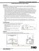
Do not use the receiver without a jumper installed on the three-pin receiver jumper. When using one receiver install
the jumper on Receiver 1 position. When using an optional second receiver, set receiver jumpers to Receiver 1
position and Receiver 2 positions, respectively. See Figure 1. The receivers should be mounted at least three feet
apart.
Reset
Reset
Green
Red
OUT - Green
VS - Red
GND - Black
Black
To LX-Bus
Modules
Black - Aux. Common
Green - Serial Data Out
Yellow - Serial Data In
Red - Aux. Positive
* Yellow Wire is not used
for 472 to FA400-DMP
connection.
472
Inovonics
900MHz
Interface
Card
Inovonics FA400-DMP
Wireless Receiver(s)
J6 Expansion
Connector
Max total distance for wiring on
one LX-Bus™ circuit is 2,500 feet.
LX-Bus™ Harness
Transmitter
Programming
Connector
FA400-DMP
Wireless Receiver
Connector
XR500 Series Control Panel
1 2
Note: Do Not use
receiver without a jumper.
1 2
Receiver 2 Position
Receiver 1 Position
Optional Second Receiver
Receiver Jumper
Receiver Jumper
s
s
s
s
s = Supervised
Figure 1: 472 Inovonics 900MHz Interface Card Wiring
Programming Wireless Zones
After programming the House Code to 99 in System Options and the zone type and area assignment for the wireless
zone, program the operating parameters for the wireless transmitters. At the NEXT ZONE? prompt, select NO
to display the wireless zone options. The transmitters connect to the 472 for programming after all zones are
programmed. See Programming Wireless Transmitters.
Note: A panel account number must be programmed before programming the wireless transmitters.
WIRELESS YES NO
Wireless
Select YES if you are programming a wireless zone. Press the COMMAND key to continue
wireless programming.
CHECK IN TM: 60
NONE 10 30 60
Check-in Time
You can set wireless transmitters to check in automatically every 10, 30, or 60 seconds
or not at all. To change the 60 second default, press any top row Select key to display
NONE 10 30 60. Press the Select key under the desired check-in time for this zone.
INT CONT NO YES
Internal Contact
Select YES to use an internal contact on the wireless transmitter. Select NO to use an
external contact. When NO, the following two prompts display.
EOL NO YES
End-of-Line
Select YES to supervise an external contact connected to the wireless transmitter.
At the contact, install a 2.2k Ohm End-of-Line resistor in parallel for Normally Open
contacts and in series for Normally Closed contacts.

472 Installation Guide Digital Monitoring Products
3
NRM OpEN NO YES
Normally Open
Select NO if the external contact connected to the transmitter is a Normally Closed
type.
NEXT ZN? NO YES
Press the COMMAND key and select NO to program the Alarm Action of the zone you
are currently programming. After programming the Alarm Action, the display returns
to ZONE NO: –. Select YES to display NEXT ZN? to program another zone. After
programming all zones, press the Back Arrow key to go directly to wireless transmitter
programming. After all zone programming is completed, connect the individual wireless
transmitters to the 472 for programming as dened below.
Enrolling Inovonics Wireless Transmitters
pRg XMTR? NO YES
Program Transmitter
Select YES to program wireless transmitters. Select NO to return to ZONE
INFORMATION.
Note: Before programming transmitters, you must program the panel's accurate
account number, which determines the transmitter House ID number. If the account
number is changed, the transmitter must be reprogrammed to reect the new House ID
number. See the section Inovonics Transmitter Information for more information about
programming transmitters and the House ID.
CONNECT XMTR: ***
Connect Transmitter
Connect the transmitter, whose zone number displays, to the Programming Connector
on the 472 Inovonics 900MHz Interface Card using the ACC620 Programming Cable.
RESET THE TRANSMITTER. The keypad display prompts you for transmitters starting
from the lowest zone number to the highest.
At the CONNECT XMTR: prompt, press any top row Select key and enter any wireless
zone number (500 to 699 for XR500 Series panels, or 000 for the C100 and FA100
transmitters). After programming all transmitters, press the COMMAND key.
CONNECT fa100
Connect Command Transmitter
Connect the C100 or FA100 you want assigned to the 472 Card. Press the Alert button on
the transmitter to initiate programming. Repeat the programming for each prompt. To
use the Alert button on the transmitter as a panic, program AMBUSH as YES in System
Reports.
XMTR pROgRaMMEd
Transmitter Programmed
Transmitter Programmed displays after the wireless transmitter is successfully
programmed into the panel.
Transmitter Programming Options
Program Option 100/113 201 202 203S/D 205S/D 206 207 209 200/210 200W/210W 250 570/575
Internal Contact
N/A No No No No No No No No No or Yes No N/A
End-of-Line
N/A No No No No No No No No or Yes No or Yes No or Yes N/A
Normally Open
N/A Yes No Ye s Yes No Yes Ye s No or Yes No or Yes* No or Yes N/A
Check-in Time
None 10-60 10-60 10-60 10-60 10-60 10-60 10-60 10-60 10-60 10-60 10-60
* Program the 210W as Normally Open when using an internal contact.
Inovonics Transmitter Information
A House ID Number is like an address for Inovonics wireless transmitters so they know with which panel they should
be communicating. The House ID Number is based on the last two digits of the panel’s primary account number.
Be sure that the panel’s primary account number is programmed before programming any wireless transmitters.
Because the House ID is based on the account number, entering or changing the primary account number after
programming the transmitters will require you to reprogram all of the transmitters.

800-641-4282
www.dmp.com 2500 North Partnership Boulevard
15135
LT-0289 1.01 © 2015 Digital Monitoring Products, Inc.
Cross Talk
If you have more than one account within a ve-mile radius, there is a possibility that “cross talk” can occur. “Cross
talk” occurs when transmitters communicate with multiple panels. This is usually due to the transmitters having the
same House ID. If you have two panels within a ve-mile radius that use wireless zones, be sure that the last two
digits of the account numbers are not the same.
For example, ABC Plumbing has a panel with an account number of 12345 that uses wireless zones. The House ID
for the wireless transmitters at ABC Plumbing is 45. Two blocks away, XYZ Printing has an account number of 22345
and the panel also uses wireless zones. The House ID for the transmitters for XYZ Printing is 45. Because the two
accounts have the same last two digits in the account numbers, the House ID is the same. Therefore, the wireless
transmitters “cross talk” and report to both panels bearing the same House ID.
To avoid “cross talk,” panels within a ve-mile radius of each other must not have the same two digits in the primary
account number. If a “cross talk” issue is already present, you must delete the wireless transmitter zones, enter the
proper account number, and then reprogram the wireless transmitters.
Wiring Specications for LX-Bus
Several factors determine the performance characteristics of the DMP LX-Bus™ and keypad bus: the length of wire
used, the number of devices connected, and the voltage at each device. When planning an LX-Bus™ and keypad bus
installation, keep in mind the following four specications:
1. DMP recommends using 18 or 22-gauge unshielded wire for all keypad and LX-Bus circuits. Do Not use twisted
pair or shielded wire for LX-Bus and keypad bus data circuits. To maintain auxiliary power integrity when
using 22-gauge wire do not exceed 500 feet. When using 18-gauge wire do not exceed 1,000 feet. Install an
additional power supply to increase the wire length or add devices.
2. Maximum distance for any one circuit (length of wire) is 2,500 feet regardless of the wire gauge. This distance
can be in the form of one long wire run or multiple branches with all wiring totaling no more than 2,500 feet.
As wire distance from the panel increases, DC voltage on the wire decreases.
3. Maximum number of devices per 2,500 foot circuit is 40.
Note: Each panel allows a specic number of supervised keypads. Add additional keypads in the unsupervised
mode. Refer to the panel installation guide for the specic number of supervised keypads allowed.
4. Maximum voltage drop between the panel (or auxiliary power supply) and any device is 2.0 VDC. If the voltage
at any device is less than the required level, add an auxiliary power supply at the end of the circuit. When
voltage is too low, the devices cannot operate properly.
Refer to the panel Installation Guide and the LX-Bus/Keypad Bus Wiring Application Note (LT-2031). Also see the
710/710F Module Installation Sheet (LT-0310) for more information.
Compliance Listing Specications
UL Commercial Fire
Any auxiliary power supply used must be regulated, power limited and listed for Fire Protective Signaling.
Specications
Primary Power 12 VDC from panel
Current Draw 85mA
Dimensions 2.25” W x 5.25” H
Compatibility
XR500 Series Command Processor panels
The 472 is required when using the FA400-DMP
Receiver
Certications
ANSI/UL 864 Fire Protective Signaling
(LX-Bus only)
ANSI/UL 985 Household Fire Warning
ANSI/UL 1023 Household Burglar
Inovonics™ Receivers and Transmitters
FA400-DMP Remote Receiver
EN4200 Remote Receiver (requires ACC8280)
ACC8280 Translator
ENES1233S Single Button Transmitter
FA100 Command Transmitter
FA113 Keychain Remote Control
FA202 Smoke Detector FA207 Glassbreak Detector
FA203S Necklace Pendant FA209 Wireless Bill Trap
FA203D Necklace Pendant FA210 Universal Transmitter
FA205S Belt Clip FA210W Universal Transmitter
FA205D Belt Clip FA223S Water-Resistant Pendant
FA206I Inovonics PIR FA250 High-Power Transmitter
FA206S Sharpshooter™ PIR FA575 Real-Time Repeater
FA715 Wireless Survey Kit
FA223S LTH Water-Resistant Pendant
/