
Dell EMC ML3 Tape Library
User's Guide


Information in this document is subject to change without notice.
Copyright © 2017 Dell Inc. or its subsidiaries. All rights reserved.
Dell, EMC, and other trademarks are trademarks of Dell Inc. or its subsidiaries. Other trademarks may
be trademarks of their respective owners.
Printed December 2017
iii

iv Dell EMC ML3 Tape Library: User's Guide

Contents
iii
Figures .............. vii
Tables ............... ix
Read this first ............ xi
Minimum firmware levels for common library
features ................ xi
Contacting Dell ............. xii
Safety and environmental notices ... xiii
Danger and Caution notices ........ xiii
Possible safety hazards .......... xvi
Class I laser product ........... xvi
Performing the safety inspection procedure ... xvii
Rack safety .............. xvii
Power Cords.............. xix
Preface .............. xxi
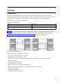
Overview .............. 1
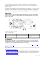
Introduction .............. 1
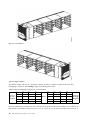
Structure and supported library configurations ... 2
Components ............. 7
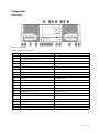
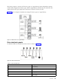
Front panel ............. 7
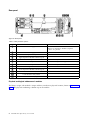
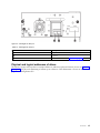
Rear panel ............. 8
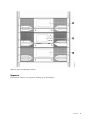
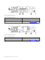
Magazines ............. 9
Power supply............ 11
Bar code reader ........... 11
User interfaces ............. 11
Supported tape drives ........... 12
Control path drives........... 12
Mixed drives ............. 12
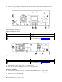
Drive sled back panels.......... 13
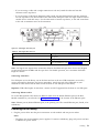
Physical and logical addresses of drives .... 15
Supported tape cartridges ......... 16
Library functions ............ 17
Encryption ............. 17
Library sharing ............ 17
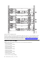
Path failover and load balancing ...... 18
Alerts and logging ........... 19
Host connectivity ............ 20
Network connectivity ........... 20
Planning .............. 23
Library Layout and Location requirements .... 23
Power cords .............. 25
Network requirements........... 30
Host requirements ............ 31
Installing .............. 33
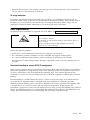
Unpacking the Base Module and Expansion
Modules ............... 34
Identifying Library Module components..... 39
Preparing top and bottom modules ...... 39
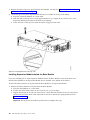
Installing modules in a rack ......... 42
Installing a tabletop module ......... 46
Aligning and connecting modules ....... 46
Validating tape drive installation ....... 49
Connecting cables ............ 49
Powering on the library .......... 51
The Initial Setup process .......... 52
Initial configuration and customization ..... 53
Labeling and loading tape cartridges ...... 53
Verifying the installation .......... 55
Advanced library configuration........ 55
Overview .............. 56
Library partitioning .......... 57
Verifying the host connection ........ 58
Managing ............. 59
The Management GUI ........... 59
The Operator Panel............ 61
Locating Management functions ....... 63
Default settings ............ 66
Methods of cleaning drives ........ 69
Accessing cartridges .......... 70
Configuring Library Managed Encryption (KMIP) 70
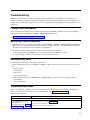
Troubleshooting........... 73
Finding event information ......... 73
Identifying a failed component ........ 73
Running library tests ........... 73
Troubleshooting Guide .......... 73
Pre-call checklist............. 76
Contacting Dell ............. 77
Diagnostic information .......... 77
The ITDT firmware update, dump retrieval and
drive test tool ............ 77
Event codes ............. 78
Main error events .......... 79
Warning error events ......... 86
Configuration Change events ...... 93
Informational events ......... 94
TapeAlert flags ............ 95
TapeAlert flags supported by the library... 95
TapeAlert flags supported by the drive ... 97
Sense data ............. 100
Drive Error Codes: Single-character display
(SCD) ............... 100
SCD dot ............. 102
Status light ............ 102
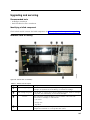
Upgrading and servicing ...... 105
Internal view of library .......... 105
v

Adding, removing, or replacing a tape drive ... 106
Adding or replacing a Base or Expansion Module 109
Adding, removing, or replacing a power supply 114
Replacing a Base or Expansion controller card .. 117
Installing, removing, or replacing an accessor and
spooling mechanism ........... 120
Returning the accessor to the Base Module .. 127
Removing or replacing a spooling mechanism .. 129
Removing or replacing a magazine ...... 133
Moving the library modules ........ 135
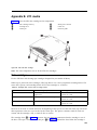
Appendix A. Library Configuration
Forms .............. 137
Library information ........... 138
Module and drive information ....... 139
Logical Library information ........ 140
Users account information ......... 141
Appendix B. LTO media ....... 143
Data cartridges ............. 143
Cartridge Read/Write compatibility ..... 144
WORM (Write Once, Read Many) cartridges ... 144
WORM media ............ 144
Data security on WORM media ...... 145
WORM media errors .......... 145
Cleaning cartridge............ 145
Labeling tape cartridges .......... 145
Guidelines for bar code labels ....... 147
Write-Protect switch ........... 147
Handling the cartridges .......... 148
Providing training ........... 148
Ensuring proper packaging........ 148
Proper acclimation and environmental
conditions ............. 149
Completing a thorough inspection ..... 150
Handling the cartridge carefully ...... 150
Environmental and shipping specifications for tape
cartridges .............. 151
Appendix C. Accessibility ...... 153
Glossary ............. 155
Index ............... 175
vi Dell EMC ML3 Tape Library: User's Guide

Figures
1. Two module tape library ........ 1
2. Base Module ............ 2
3. Expansion Module .......... 3
4. Base Module ............ 3
5. 2 module library ........... 3
6. 3 module library ........... 3
7. 4 module library ........... 4
8. 5 module library ........... 4
9. 6 Module library ........... 5
10. 7 module library ........... 6
11. Front panel ............. 7
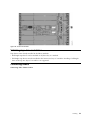
12. Rear panel ............. 8
13. Physical numbering of modules ...... 9
14. Left magazine............ 10
15. Right magazine ........... 10
16. Power supply rear panel LEDs ...... 11
17. Mixed drives in a logical library ..... 13
18. Drive sled indicators ......... 13
19. Half-height SAS dual port........ 14
20. Half-height FC single port ....... 14
21. Full-height FC dual port ........ 15
22. Physical numbering of drives ...... 16
23. Types of receptacles.......... 30
24. Removing the module from the box .... 34
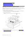
25. The module after removal from the box 35
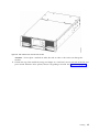
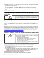
26. Unlatching the top of the module ..... 36
27. Removing the top of the module ..... 36
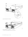
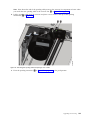
28. The module is opened to show the foam
packing............... 37
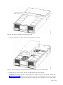
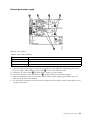
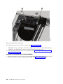
29. The foam packing is removed, and the internal
components are shown - Base Module. ... 37
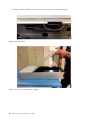
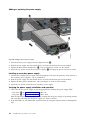
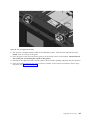
30. Top cover sensor ........... 38
31. Incorrect top cover insertion - too high 38
32. Correct top cover insertion ....... 39
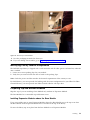
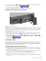
33. Lowering the front of the top cover .... 40
34. Unlocking the spring loaded lock ..... 41
35. Removing the cover.......... 41
36. Lifting the cover and locking it ...... 42
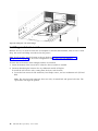
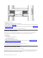
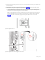
37. Universal rack connector ........ 43
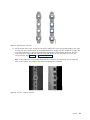
38. Incorrect connector locations ....... 43
39. Correct connector locations ....... 44
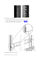
40. Mounting the rails to the connectors .... 44
41. Side rails installed .......... 45
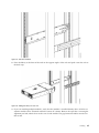
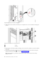
42. Sliding the library into the rack ...... 45
43. Library in the rack .......... 46
44. Alignment lever lock ......... 47
45. Alignment lever locked or engaged to lower
module .............. 47
46. Alignment lever unlocked or disengaged 48
47. Two modules in rack, seen from the rear 48
48. Connected modules .......... 49
49. Full-height FC dual port ........ 50
50. Half-height FC single port ....... 50
51. Half-height SAS dual port........ 51
52. IP address selection .......... 52
53. Open I/O station seen from the left .... 54
54. Magazine pulled out ......... 55
55. Management GUI main screen ...... 60
56. Operator Panel main screen ....... 62
57. Front panel LEDs .......... 63
58. Internal view of the library ....... 105
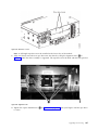
59. Drive bay covers .......... 107
60. Alignment rails ........... 107
61. Installing a tape drive......... 108
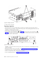
62. Unlocking the drive ......... 108
63. Interconnect cables .......... 111
64. Unlocking or disengaging the alignment lever 112
65. Loosening the thumbscrews....... 113
66. Sliding the module out of the rack .... 113
67. Power supplies ........... 115
68. Sliding in the new power supply ..... 116
69. Controller card components....... 118
70. Installing a Controller card ....... 119
71. Magazine release levers ........ 121
72. Unlocking the robot ......... 122
73. Finger holes ............ 122
74. Unlocking the spooling cable and placing it in
its cradle ............. 123
75. Spooling cable in park position ..... 124
76. Pins are aligned horizontally ...... 125
77. Installing the spooling cable ...... 126
78. Inserting the screwdriver to manually operate
the accessor ............ 128
79. Left magazine opening ........ 128
80. Unlocking the spooling mechanism .... 130
81. Unlocked spooling mechanism - enlarged
view .............. 131
82. Locked spooling mechanism - enlarged view 132
83. Removing the spooling mechanism .... 133
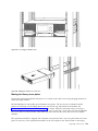
84. Manually releasing the right magazine 134
85. Manually releasing the left magazine 134
86. The LTO data cartridge ........ 143
87. LTO Data and WORM tape cartridges 145
88. Sample bar code label on the LTO 8 Tape
Cartridge ............. 147
89. Setting the write-protect switch ..... 148
90. Double-boxing tape cartridges for shipping 149
91. Checking for gaps in the seams of a cartridge 150
vii

viii Dell EMC ML3 Tape Library: User's Guide

Tables
1. Regulatory marks .......... xi
2. Minimum firmware levels for common library
features .............. xi
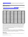
3. Module designations .......... 1
4. Minimum and maximum storage configurations 2
5. Library configurations ......... 3
6. Front panel descriptions......... 7
7. Rear panel descriptions ......... 8
8. Physical numbering of storage slots - bottom
module .............. 10
9. Power supply LEDs .......... 11
10. Supported tape drives ......... 12
11. Drive sled indicators ......... 13
12. Half-height SAS dual port........ 14
13. Half-height FC single port ....... 14
14. Full-height FC dual port ........ 15
15. Differences between CPF and DPF ..... 18
16. Location requirements ......... 23
17. Physical specifications ......... 24
18. Electrical specifications......... 24
19. Equipment environmental specifications 24
20. Gas and particulate exposure ...... 25
21. Power cords ............ 26
22. Installation Precautions ........ 33
23. Full-height FC dual port ........ 50
24. Half-height FC single port ....... 50
25. Half-height SAS dual port........ 51
26. Main screen elements ......... 60
27. Navigation Dock ........... 61
28. Status icons ............ 61
29. Operator Panel menu tree........ 62
30. Front panel LEDs .......... 63
31. Locating Management functions ..... 63
32. Default settings ........... 66
33. Magazine state ........... 70
34. Resolving errors ........... 73
35. Main error events .......... 79
36. Warning events ........... 86
37. Configuration Change events ...... 93
38. Informational Events ......... 94
39. Error codes on the single-character display 101
40. Meaning of Status light and single-character
display (SCD) ........... 102
41. Internal view description ....... 105
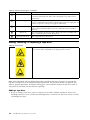
42. Pinch hazard............ 106
43. Power supply components ....... 115
44. Controller card components....... 118
45. Cartridge data capacity and recording formats 143
46. Nominal cartridge life: Load/unload cycles 144
47. Data cartridge compatibility with LTO tape
drive .............. 144
48. Cartridges and VOLSERs compatible with the
LTO Tape Drives .......... 146
49. Location of the write-protect switch .... 148
50. Environment for operating, storing, and
shipping the LTO Ultrium Tape Cartridge .. 151
ix

x Dell EMC ML3 Tape Library: User's Guide

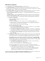
Read this first
Regulatory information
v The library must be installed in a restricted area.
v Only personnel with technical and product safety training should have access to the library.
v To comply with the regulations and standards, the library must be properly installed in an office or
industrial environment with shielded cables and adequate grounding of SAS interface and input
power.
v Models: 3555-L3A, 3555-E3A
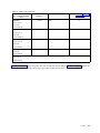
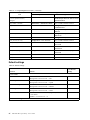
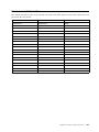
Table 1. Regulatory marks
The CE mark is a mandatory conformity mark on many products that are
placed on the single market in the European Economic Area (EEA). The
CE marking certifies that a product meets EU consumer safety, health, or
environmental requirements.
CSA C22-2 No.60950-1 - Electrical safety - UL 60950-1 68475
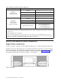
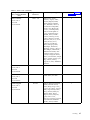
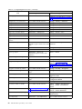
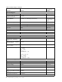
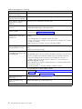
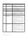
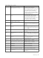
Minimum firmware levels for common library features
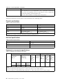
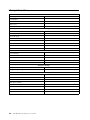
Table 2. Minimum firmware levels for common library features
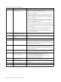
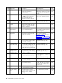
Feature Minimum Firmware Levels Required
LTO8 (HH/FH) Tape Drives Library Firmware must be at 1.1.1.0 or greater to support
the LTO8 tape drives. Ensure that any host applications
and device drivers are at the minimum level that is
required to support LTO8 tape drives.
LTO6 (HH/FH) and LTO7 (HH/FH) Tape Drives Library Firmware must be at 1.1.0.1-A00 or greater to
support the LTO6 and LTO7 tape drives. Ensure that any
host applications and device drivers are at the minimum
level that is required to support LTO6 and LTO7 tape
drives.
Library Managed Encryption Library Firmware must be at 1.1.1.0-A00 or greater to
support the Library Managed Encryption feature. Ensure
that any key manager applications are at the minimum
level that is required to support the 3U library.
Path Failover (Control Path and Data Path) Library Firmware must be at 1.1.1.0-A00 or greater to
support the Path Failover feature. Ensure that any device
drivers are at the minimum level that is required to
support the 3U library.
xi

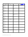
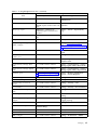
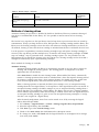
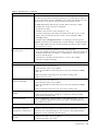
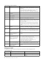
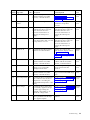
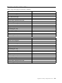
Table 2. Minimum firmware levels for common library features (continued)
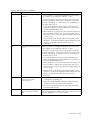
Feature Minimum Firmware Levels Required
Remote Logging (rsyslog) Library Firmware must be at 1.1.1.0-A00 or greater to
support the Remote Logging feature. Ensure that any
device drivers are at the minimum level that is required
to support the 3U library.
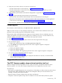
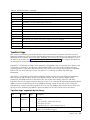
Contacting Dell
For customers in the United States, call 800-WWW-DELL (800-999-3355).
Note: If you do not have an active Internet connection, you can find contact information about your
purchase invoice, packing slip, bill, or Dell product catalog.
Dell provides online and telephone-based support and service options. Service availability varies by
country and product, and some services might not be available in your area. To contact Dell for sales,
technical support, or customer service issues follow the steps that are listed:
1. Go to www.Dell.com/support.
2. Select your country from the drop-down menu on the lower right corner of the page.
3. For customized support:
a. Enter your system Service Tag in the Enter your Service Tag field.
b. Click Submit. The support page that lists the various support categories is displayed.
4. For general support:
a. Select your product category.
b. Select your product segment.
c. Select your product. The support page that lists the various support categories is displayed.
5. For contact details of Dell Global Technical Support:
a. Click Global Technical Support.
b. The Contact Technical Support page is displayed with details to call, chat, or e-mail the Dell
Global Technical Support team.
xii Dell EMC ML3 Tape Library: User's Guide

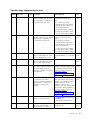
Safety and environmental notices
When this product is used, observe the danger, caution, and attention notices that are contained in this
guide. The notices are accompanied by symbols that represent the severity of the safety condition.
The sections that follow define each type of safety notice and give examples.
Danger and Caution notices
Danger notices
A danger notice calls attention to a situation that is potentially lethal or extremely hazardous to people. A
lightning bolt symbol always accompanies a danger notice to represent a dangerous electrical condition.
xiii

To prevent a possible shock from touching two surfaces with different
protective ground (earth), use one hand, when possible, to connect or
disconnect signal cables. (D001)
Overloading a branch circuit is potentially a fire hazard and a shock hazard
under certain conditions. To avoid these hazards, ensure that your system
electrical requirements do not exceed branch circuit protection requirements.
Refer to the information that is provided with your device or the power
rating label for electrical specifications. (D002)
If the receptacle has a metal shell, do not touch the shell until you have
completed the voltage and grounding checks. Improper wiring or grounding
could place dangerous voltage on the metal shell. If any of the conditions
are not as described, STOP. Ensure the improper voltage or impedance
conditions are corrected before proceeding. (D003)
An electrical outlet that is not correctly wired could place hazardous voltage
on metal parts of the system or the devices that attach to the system. It is
the responsibility of the customer to ensure that the outlet is correctly wired
and grounded to prevent an electrical shock. A lightning bolt symbol always
accompanies a danger notice to represent a dangerous electrical condition.
(D004)
When working on or around the system, observe the following precautions:
Electrical voltage and current from power, telephone, and communication
cables are hazardous. To avoid a shock hazard:
v If Dell supplied a power cord(s), connect power to this unit only with the
Dell provided power cord. Do not use the Dell provided power cord for
any other product.
v Do not open or service any power supply assembly.
v Do not connect or disconnect any cables or perform installation,
maintenance, or reconfiguration of this product during an electrical storm.
v The product might be equipped with multiple power cords. To remove all
hazardous voltages, disconnect all power cords.
v Connect all power cords to a properly wired and grounded electrical
outlet. Ensure that the outlet supplies proper voltage and phase rotation
according to the system rating plate.
v Connect any equipment that will be attached to this product to properly
wired outlets.
v When possible, use one hand only to connect or disconnect signal cables.
v Never turn on any equipment when there is evidence of fire, water, or
structural damage.
v Do not attempt to switch on power to the machine until all possible
unsafe conditions are corrected.
v Assume that an electrical safety hazard is present. Perform all continuity,
grounding, and power checks specified during the subsystem installation
procedures to ensure that the machine meets safety requirements.
v Do not continue with the inspection if any unsafe conditions are present.
v Disconnect the attached power cords, telecommunications systems,
networks, and modems before you open the device covers, unless
instructed otherwise in the installation and configuration procedures.
v Connect and disconnect cables as described in the following procedures
when installing, moving, or opening covers on this product or attached
devices.
xiv Dell EMC ML3 Tape Library: User's Guide

To disconnect:
1. Turn off everything (unless instructed otherwise).
2. Remove the power cords from the outlets.
3. Remove the signal cables from the connectors.
4. Remove all cables from the devices.
To connect:
1. Turn off everything (unless instructed otherwise).
2. Attach all cables to the devices.
3. Attach the power cords to the outlets.
4. Turn on the devices.
v Sharp edges, corners and joints may be present in and around the system.
Use care when handling equipment to avoid cuts, scrapes and pinching.
(D005)
Heavy equipment - personal injury or equipment damage might result if
mishandled. (D006)
DANGER: Multiple power cords. The product might be equipped with
multiple power cords. To remove all hazardous voltages, disconnect all
power cords. (L003)
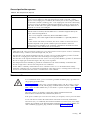
Caution notices
A caution notice calls attention to a situation that is potentially hazardous to people because of some
existing condition, or to a potentially dangerous situation that might develop because of some unsafe
practice.
The doors and covers to the product are to be closed at all times except for
service by trained service personnel. All covers must be replaced and doors
closed at the conclusion of the service operation. (C013)
This product is equipped with a 3-wire (two conductors and ground) power
cable and plug. Use this power cable with a properly grounded electrical
outlet to avoid electrical shock. (C018)
This assembly contains mechanical moving parts. Use care when servicing
this assembly. (C025)
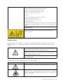
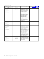
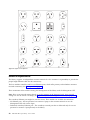
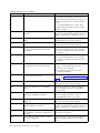
A caution notice can be accompanied by one of several symbols:
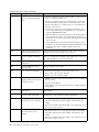
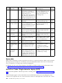
If the symbol is... It means...
A generally hazardous condition not represented by other safety symbols.
A hazardous condition due to the use of a laser in the product. Laser
symbols are always accompanied by the classification of the laser as defined
by the U. S. Department of Health and Human Services (for example, Class
I, Class II, and so forth).
Safety and environmental notices xv

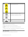
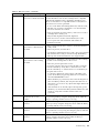
If the symbol is... It means...
Risk of hand pinching, can trap hands, fingers and cause serious injury.
Keep hands clear during operation (L012).
The weight of this part or unit is between 18.1 and 33.6 kg (40 and 74 lb). It
takes two persons to safely lift this part or unit. (C009)
The weight of this part or unit is between 33.6 and 46.3 kg (74 and 102 lb).
It takes three persons to safely lift this part or unit. (C010)
A hazardous condition due to the unit's susceptibility to electrostatic
discharge.
Possible safety hazards
Possible safety hazards to the operation of this product are:
Electrical
An electrically charged frame can cause serious electrical shock.
Mechanical
Hazards (for example, a safety cover missing) are potentially harmful to people.
Chemical
Do not use solvents, cleaners, or other chemicals that are not approved for use on this product.
Before the library is used, repair any of the preceding problems.
Class I laser product
Before the library is used, review the following laser safety information.
xvi Dell EMC ML3 Tape Library: User's Guide

The product might contain a laser assembly that complies with the performance standards set by the US
Food and Drug Administration for a Class I laser product. Class I laser products do not emit hazardous
laser radiation. The product has the necessary protective housing and scanning safeguards to ensure that
laser radiation is inaccessible during operation or is within Class I limits. External safety agencies
reviewed the product and obtained approvals to the latest standards as they apply.
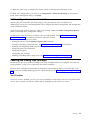
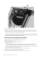
Performing the safety inspection procedure
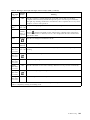
Before you service the unit, complete the following safety inspection procedure.
1. Stop all activities between the host and the library’s tape drives.
2. Turn off the power to the library by pushing in the Power button on the front of the tape library for 4
seconds.
3. Unplug the library’s power cord from the electrical outlet and the library’s power supply unit.
4. Check the library’s power cords for damage, such as a pinched, cut, or frayed cord.
5. If drives are FC/SAS attached, check the tape drive's FC/SAS cable for damage.
6. Check the top and bottom covers of the library for sharp edges, damage, or alterations that expose its
internal parts.
7. Check the top and bottom covers of the library for proper fit. They must be in place and secure.
8. Check the product label at the rear of the library to make sure that it matches the voltage at your
outlet.
Rack safety
The following general safety information must be used for all rack-mounted devices.
DANGER
Observe the following precautions when working on or around your IT rack system.
v Heavy equipment - personal injury or equipment damage might result if mishandled.
v Always lower the leveling pads on the rack cabinet.
v Always install stabilizer brackets on the rack cabinet.
v To avoid hazardous conditions due to uneven mechanical loading, always install the heaviest devices
in the bottom of the rack cabinet. Always install servers and optional devices starting from the bottom
of the rack cabinet.
v Rack-mounted devices are not to be used as shelves or work spaces. Do not place objects on top of
rack-mounted devices.
v Each rack cabinet might have more than one power cord. Be sure to disconnect all power cords in the
rack cabinet when directed to disconnect power during servicing.
v Connect all devices installed in a rack cabinet to power devices installed in the same rack cabinet. Do
not plug a power cord from a device installed in one rack cabinet into a power device installed in a
different rack cabinet.
Safety and environmental notices xvii

v An electrical outlet that is not correctly wired could place hazardous voltage on the metal parts of the
system or the devices that attach to the system. It is the responsibility of the customer to ensure that
the outlet is correctly wired and grounded to prevent an electrical shock. (R001 part 1 of 2)
Caution
v Do not install a unit in a rack where the internal rack ambient temperatures might exceed the
manufacturer's recommended ambient temperature for all your rack-mounted devices.
v Do not install a unit in a rack where the air flow is compromised. Ensure that air flow is not blocked
or reduced on any side, front, or back of a unit that is used for air flow through the unit.
v Consideration must be given to the connection of the equipment to the supply circuit so that
overloading of the circuits does not compromise the supply wiring or overcurrent protection. To
provide the correct power connection to a rack, refer to the rating labels on the equipment in the rack
to determine the total power requirement of the supply circuit.
v (For sliding drawers) Do not pull out or install any drawer or feature if the rack stabilizer brackets are
not attached to the rack. Do not pull out more than one drawer at a time. The rack might become
unstable if you pull out more than one drawer at a time.
v (For fixed drawers) This drawer is a fixed drawer and must not be moved for servicing unless
specified by the manufacturer. Attempting to move the drawer partially or out of the rack might cause
the rack to become unstable or cause the drawer to fall out of the rack. (R001 part 2 of 2)
Caution
Removing components from the upper positions in the rack cabinet improves rack stability during
relocation. Follow these general guidelines whenever you relocate a populated rack cabinet within a room
or building:
v Reduce the weight of the rack cabinet by removing equipment, starting at the top of the rack cabinet.
When possible, restore the rack cabinet to the configuration of the rack cabinet as you received it. If
this configuration is not known, you must do the following:
– Remove all devices in the 32U position (compliance ID RACK-001) or 22U (compliance ID RR001)
and above.
– Ensure that the heaviest devices are installed in the bottom of the rack cabinet.
xviii Dell EMC ML3 Tape Library: User's Guide

– Ensure that there are little-to-no empty U-levels between devices installed in the rack-cabinet below
the 32U (compliance ID RACK-001) or 22U (compliance ID RR001) level, unless the received
configuration specifically allowed it.
v If the rack cabinet you are relocating is part of a suite of rack cabinets, detach the rack cabinet from the
suite.
v If the rack cabinet you are relocating was supplied with removable outriggers, they must be reinstalled
before the cabinet is relocated.
v Inspect the route that you plan to take to eliminate potential hazards.
v Verify that the route that you choose can support the weight of the loaded rack cabinet. Refer to the
documentation that comes with your rack cabinet for the weight of a loaded rack cabinet.
v Verify that all door openings are at least 760 x 2032 mm (30 x 80 in.).
v Ensure that all devices, shelves, drawers, doors, and cables are secure.
v Ensure that the four leveling pads are raised to their highest position.
v Ensure that no stabilizer bracket is installed on the rack cabinet during movement.
v Do not use a ramp that is inclined at more than 10 degrees.
v When the rack cabinet is in the new location, complete these steps.
– Lower the four leveling pads.
– Install stabilizer brackets on the rack cabinet.
– If you removed any devices from the rack cabinet, repopulate the rack cabinet from the lowest
position to the highest position.
v If a long-distance relocation is required, restore the rack cabinet to the configuration of the rack cabinet
as you received it. Pack the rack cabinet in the original packaging material, or equivalent. Also, lower
the leveling pads to raise the casters off the pallet and bolt the rack cabinet to the pallet. (R002)
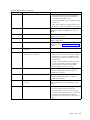
Power Cords
For your safety, Dell provides a power cord with a grounded attachment plug to use with this Dell
product. To avoid electrical shock, always use the power cord and plug with a properly grounded outlet.
Dell power cords used in the United States and Canada are listed by Underwriter’s Laboratories (UL)
and certified by the Canadian Standards Association (CSA).
For units intended to be operated at 115 volts: Use a UL-listed and CSA-certified cord set consisting of a
minimum 18 AWG, Type SVT or SJT, three-conductor cord, a maximum of 15 feet in length and a parallel
blade, grounding-type attachment plug rated 15 amperes, 125 volts.
For units intended to be operated at 230 volts (U.S. use): Use a UL-listed and CSA-certified cord set
consisting of a minimum 18 AWG, Type SVT or SJT, three-conductor cord, a maximum of 15 feet in
length and a tandem blade, grounding-type attachment plug rated 15 amperes, 250 volts.
For units intended to be operated at 230 volts (outside the U.S.): Use a cord set with a grounding-type
attachment plug. The cord set should have the appropriate safety approvals for the country in which the
equipment will be installed.
Dell power cords for a specific country or region are usually available only in that country or region.
Safety and environmental notices xix

xx Dell EMC ML3 Tape Library: User's Guide
Page is loading ...
Page is loading ...
Page is loading ...
Page is loading ...
Page is loading ...
Page is loading ...
Page is loading ...
Page is loading ...
Page is loading ...
Page is loading ...
Page is loading ...
Page is loading ...
Page is loading ...
Page is loading ...
Page is loading ...
Page is loading ...
Page is loading ...
Page is loading ...
Page is loading ...
Page is loading ...
Page is loading ...
Page is loading ...
Page is loading ...
Page is loading ...
Page is loading ...
Page is loading ...
Page is loading ...
Page is loading ...
Page is loading ...
Page is loading ...
Page is loading ...
Page is loading ...
Page is loading ...
Page is loading ...
Page is loading ...
Page is loading ...
Page is loading ...
Page is loading ...
Page is loading ...
Page is loading ...
Page is loading ...
Page is loading ...
Page is loading ...
Page is loading ...
Page is loading ...
Page is loading ...
Page is loading ...
Page is loading ...
Page is loading ...
Page is loading ...
Page is loading ...
Page is loading ...
Page is loading ...
Page is loading ...
Page is loading ...
Page is loading ...
Page is loading ...
Page is loading ...
Page is loading ...
Page is loading ...
Page is loading ...
Page is loading ...
Page is loading ...
Page is loading ...
Page is loading ...
Page is loading ...
Page is loading ...
Page is loading ...
Page is loading ...
Page is loading ...
Page is loading ...
Page is loading ...
Page is loading ...
Page is loading ...
Page is loading ...
Page is loading ...
Page is loading ...
Page is loading ...
Page is loading ...
Page is loading ...
Page is loading ...
Page is loading ...
Page is loading ...
Page is loading ...
Page is loading ...
Page is loading ...
Page is loading ...
Page is loading ...
Page is loading ...
Page is loading ...
Page is loading ...
Page is loading ...
Page is loading ...
Page is loading ...
Page is loading ...
Page is loading ...
Page is loading ...
Page is loading ...
Page is loading ...
Page is loading ...
Page is loading ...
Page is loading ...
Page is loading ...
Page is loading ...
Page is loading ...
Page is loading ...
Page is loading ...
Page is loading ...
Page is loading ...
Page is loading ...
Page is loading ...
Page is loading ...
Page is loading ...
Page is loading ...
Page is loading ...
Page is loading ...
Page is loading ...
Page is loading ...
Page is loading ...
Page is loading ...
Page is loading ...
Page is loading ...
Page is loading ...
Page is loading ...
Page is loading ...
Page is loading ...
Page is loading ...
Page is loading ...
Page is loading ...
Page is loading ...
Page is loading ...
Page is loading ...
Page is loading ...
Page is loading ...
Page is loading ...
Page is loading ...
Page is loading ...
Page is loading ...
Page is loading ...
Page is loading ...
Page is loading ...
Page is loading ...
Page is loading ...
Page is loading ...
Page is loading ...
Page is loading ...
Page is loading ...
Page is loading ...
Page is loading ...
Page is loading ...
Page is loading ...
Page is loading ...
Page is loading ...
Page is loading ...
Page is loading ...
Page is loading ...
Page is loading ...
Page is loading ...
Page is loading ...
Page is loading ...
Page is loading ...
Page is loading ...
Page is loading ...
Page is loading ...
Page is loading ...
Page is loading ...
Page is loading ...
Page is loading ...
Page is loading ...
Page is loading ...
Page is loading ...
Page is loading ...
Page is loading ...
Page is loading ...
Page is loading ...
Page is loading ...
Page is loading ...
Page is loading ...
Page is loading ...
Page is loading ...
Page is loading ...
Page is loading ...
-
 1
1
-
 2
2
-
 3
3
-
 4
4
-
 5
5
-
 6
6
-
 7
7
-
 8
8
-
 9
9
-
 10
10
-
 11
11
-
 12
12
-
 13
13
-
 14
14
-
 15
15
-
 16
16
-
 17
17
-
 18
18
-
 19
19
-
 20
20
-
 21
21
-
 22
22
-
 23
23
-
 24
24
-
 25
25
-
 26
26
-
 27
27
-
 28
28
-
 29
29
-
 30
30
-
 31
31
-
 32
32
-
 33
33
-
 34
34
-
 35
35
-
 36
36
-
 37
37
-
 38
38
-
 39
39
-
 40
40
-
 41
41
-
 42
42
-
 43
43
-
 44
44
-
 45
45
-
 46
46
-
 47
47
-
 48
48
-
 49
49
-
 50
50
-
 51
51
-
 52
52
-
 53
53
-
 54
54
-
 55
55
-
 56
56
-
 57
57
-
 58
58
-
 59
59
-
 60
60
-
 61
61
-
 62
62
-
 63
63
-
 64
64
-
 65
65
-
 66
66
-
 67
67
-
 68
68
-
 69
69
-
 70
70
-
 71
71
-
 72
72
-
 73
73
-
 74
74
-
 75
75
-
 76
76
-
 77
77
-
 78
78
-
 79
79
-
 80
80
-
 81
81
-
 82
82
-
 83
83
-
 84
84
-
 85
85
-
 86
86
-
 87
87
-
 88
88
-
 89
89
-
 90
90
-
 91
91
-
 92
92
-
 93
93
-
 94
94
-
 95
95
-
 96
96
-
 97
97
-
 98
98
-
 99
99
-
 100
100
-
 101
101
-
 102
102
-
 103
103
-
 104
104
-
 105
105
-
 106
106
-
 107
107
-
 108
108
-
 109
109
-
 110
110
-
 111
111
-
 112
112
-
 113
113
-
 114
114
-
 115
115
-
 116
116
-
 117
117
-
 118
118
-
 119
119
-
 120
120
-
 121
121
-
 122
122
-
 123
123
-
 124
124
-
 125
125
-
 126
126
-
 127
127
-
 128
128
-
 129
129
-
 130
130
-
 131
131
-
 132
132
-
 133
133
-
 134
134
-
 135
135
-
 136
136
-
 137
137
-
 138
138
-
 139
139
-
 140
140
-
 141
141
-
 142
142
-
 143
143
-
 144
144
-
 145
145
-
 146
146
-
 147
147
-
 148
148
-
 149
149
-
 150
150
-
 151
151
-
 152
152
-
 153
153
-
 154
154
-
 155
155
-
 156
156
-
 157
157
-
 158
158
-
 159
159
-
 160
160
-
 161
161
-
 162
162
-
 163
163
-
 164
164
-
 165
165
-
 166
166
-
 167
167
-
 168
168
-
 169
169
-
 170
170
-
 171
171
-
 172
172
-
 173
173
-
 174
174
-
 175
175
-
 176
176
-
 177
177
-
 178
178
-
 179
179
-
 180
180
-
 181
181
-
 182
182
-
 183
183
-
 184
184
-
 185
185
-
 186
186
-
 187
187
-
 188
188
-
 189
189
-
 190
190
-
 191
191
-
 192
192
-
 193
193
-
 194
194
-
 195
195
-
 196
196
-
 197
197
-
 198
198
-
 199
199
-
 200
200
-
 201
201
-
 202
202


Dell 3555-L3A User manual
- Category
- Tape auto loaders & libraries
- Type
- User manual
Ask a question and I''ll find the answer in the document
Finding information in a document is now easier with AI
Related papers
-
Dell EMC ML3 User guide
-
-
Dell PowerVault TL2000 User guide
-
-
Dell PowerVault LTO7 User guide
-
-
-
Dell PowerVault LTO3-060 User guide
-
-
Dell TL1000 User guide
Other documents
-
IBM HH LTO User manual
-
-
Lenovo ThinkServe LTO User manual
-
HP G3 User manual
-
-
Tandberg Data LTO-5 User manual
-
HP 7115w User manual
-
-
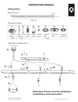 Qazqa Plafondplaat zwart 120cm voor 2, 3 of 5 hanglampen User manual
-
Quantum LTO-5 Owner's manual
