Potter PAD100-MIM User manual

Category
Fire protection
Type
User manual

This manual is also suitable for

Potter PAD100-MIM is a micro input module used for monitoring the status of an initiating device that contains a normally open set of dry contacts. Designed for use with compatible addressable fire systems, it features supervised wiring for terminals SLC+, SLC-, and IN, with a maximum wiring resistance of 100 ohms and capacitance of 1μF on the IDC circuit. The module operates within a voltage range of 24.0V and can withstand temperatures between 32°F and 120°F (0°C to 49°C). Additionally, it has a maximum of 127 units per loop and comes with a 5.1K ohm EOL resistor.

Potter PAD100-MIM is a micro input module used for monitoring the status of an initiating device that contains a normally open set of dry contacts. Designed for use with compatible addressable fire systems, it features supervised wiring for terminals SLC+, SLC-, and IN, with a maximum wiring resistance of 100 ohms and capacitance of 1μF on the IDC circuit. The module operates within a voltage range of 24.0V and can withstand temperatures between 32°F and 120°F (0°C to 49°C). Additionally, it has a maximum of 127 units per loop and comes with a 5.1K ohm EOL resistor.

PAGE 1 OF 2
Installation Manual: PAD100-MIM Micro Input Module
NOTICE TO THE INSTALLER
This manual provides an overview and the installation instructions for the PAD100-MIM module. This module is only compatible
with addressable re systems that utilize the PAD Addressable Protocol.
All terminals are power limited and should be wired in accordance with the requirements of NFPA 70 (NEC) and NFPA 72 (National
Fire Alarm Code). Failure to follow the wiring diagrams in the following pages will cause the system to not operate as intended. For
further information, refer to the control panel installation instructions.
The module shall only be installed with listed control panels. Refer to the control panel installation manual for proper system
operation.
1. Description
The PAD100-MIM is used to monitor the status of an initiating device(s) that contain a normally open set of dry contacts. The
module is enclosed in a plastic case to protect against inadvertent shorts and ground faults. The case can be mounted using a
single screw. Generally the PAD100-MIM is used to monitor pull stations and other devices where the module is installed in an
electrical box or enclosure behind the device being monitored.
The PAD100-MIM includes one red LED to indicate the module's status. In normal condition, the LED ashes when the device is
being polled by the control panel. When an input is activated, the LED will ash at a fast rate. If the LED blink has been disabled
via the programming software in a normal condition the LED of the device will be off. All other conditions remain the same.
2. Setting the Address
All PAD protocol detectors and modules require an address prior to connection to the panel's SLC loop. Each PAD device's
address (i.e., detector and/or module) is set by changing the dip switches located on the device. PAD device addresses are
comprised of a seven (7) position dip switch used to program each device with an address ranging from 1–127.
Figure 1. PAD Device Dip Switch Addresses Table (Addresses 1127)
Note: Each "gray" box indicates that the dip switch is "On," and each "white" box indicates "Off."
The examples shown below illustrate a PAD device's dip switch settings: the 1st example shows a device not addressed where all
dip switch settings are in the default "Off" position, the 2nd illustrates an addressed PAD device via the dip switch settings.
Figure 2. Examples of PAD Device Showing Default Dip Switch Setting (Unaddressed) & Addressed PAD Device
Document 5406302-A 02/16
Potter Electric Signal Company, LLC St. Louis, MO Phone: (800) 325-3936 www.pottersignal.com
Off
On
1 2 4 16
8 32 64 All dip switches are
shown in the "Off"
position. Off
On
1 2 4 16
832 64 Example shows this PAD device's
address = 42. Dip switches #2, 8 &
32 are in the "On" position.
1 2 4 8 16 32 64 1 2 4 8 16 32 64 1 2 4 8 16 32 64 1 2 4 8 16 32 64 1 2 4 8 16 32 64
1 27 53 78 103
2 28 54 79 104
3 29 55 80 105
4 30 56 81 106
5 31 57 82 107
6 32 58 83 108
7 33 59 84 109
8 34 60 85 110
9 35 61 86 111
10 36 62 87 112
11 37 63 88 113
12 38 64 89 114
13 39 65 90 115
14 40 66 91 116
15 41 67 92 117
16 42 68 93 118
17 43 69 94 119
18 44 70 95 120
19 45 71 96 121
20 46 72 97 122
21 47 73 98 123
22 48 74 99 124
23 49 75 100 125
24 50 76 101 126
25 51 77 102 127
26 52 1 2 4 8 16 32 64 1 2 4 8 16 32 64 1 2 4 8 16 32 64
1 2 4 8 16 32 64 1 2 4 8 16 32 64
PAGE 2 OF 2
INSTALLATION MANUAL: PAD100-MIM MICRO INPUT MODULE
Document 5406302-A 02/16
Potter Electric Signal Company, LLC St. Louis, MO Phone: (800) 325-3936 www.pottersignal.com
Before connecting a device to the SLC loop, take the following precautions to prevent potential damage to the SLC or device.
Power to the SLC is removed.
Field wiring on module is correctly installed.
Field wiring has no open or short circuits.
3. Technical Specications
Operating Voltage 24.0V
Max SLC Standby Current 200 μ A
Max SLC Alarm Current 200 μ A
IDC Input Circuit Class B
Max Wiring Resistance of IDC 100 Ω
Max Wiring Capacitance of IDC 1μF
Max IDC Voltage 2.05 VDC
Max IDC Current 120 μ A
EOL Resistor 5.1K Ω
Operating Temperature Range 32̊ to 120̊ F (0̊ to 49̊ C)
Operating Humidity Range 0 to 93% (non-condensing)
Max no. of Module Per Loop 127 units
Dimensions 1.75" L x 1.36" W x 43" D
Mounting Options 2-1/2" deep single-gang box
Shipping Weight 0.3 lbs
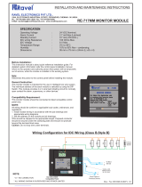
4. Wiring Diagram
Below is an wiring diagram showing how to wire a PAD100-MIM module to the panel.
Figure 3. Example of Wiring a PAD100-MIM
FROM FACP OR PREVIOUS
DEVICE AND TO NEXT DEVICE
TO NORMALLY OPEN
MONITORED DEVICE
5.1K OHM REQUIRED
Part #3005013
Notes:
SLC wiring style supports the Class A, Class B and Class X.
IDC wiring style is Class B.
SLC loop wiring (SLC+, SLC-) and initiating device wiring (IN)
are power limited.
Wiring for terminals SLC+, SLC- are supervised.
Wiring for terminals (IN) are supervised.
This addressable module does not support 2-wire detectors.
All wiring is between #12 (max.) and #22 (min.).
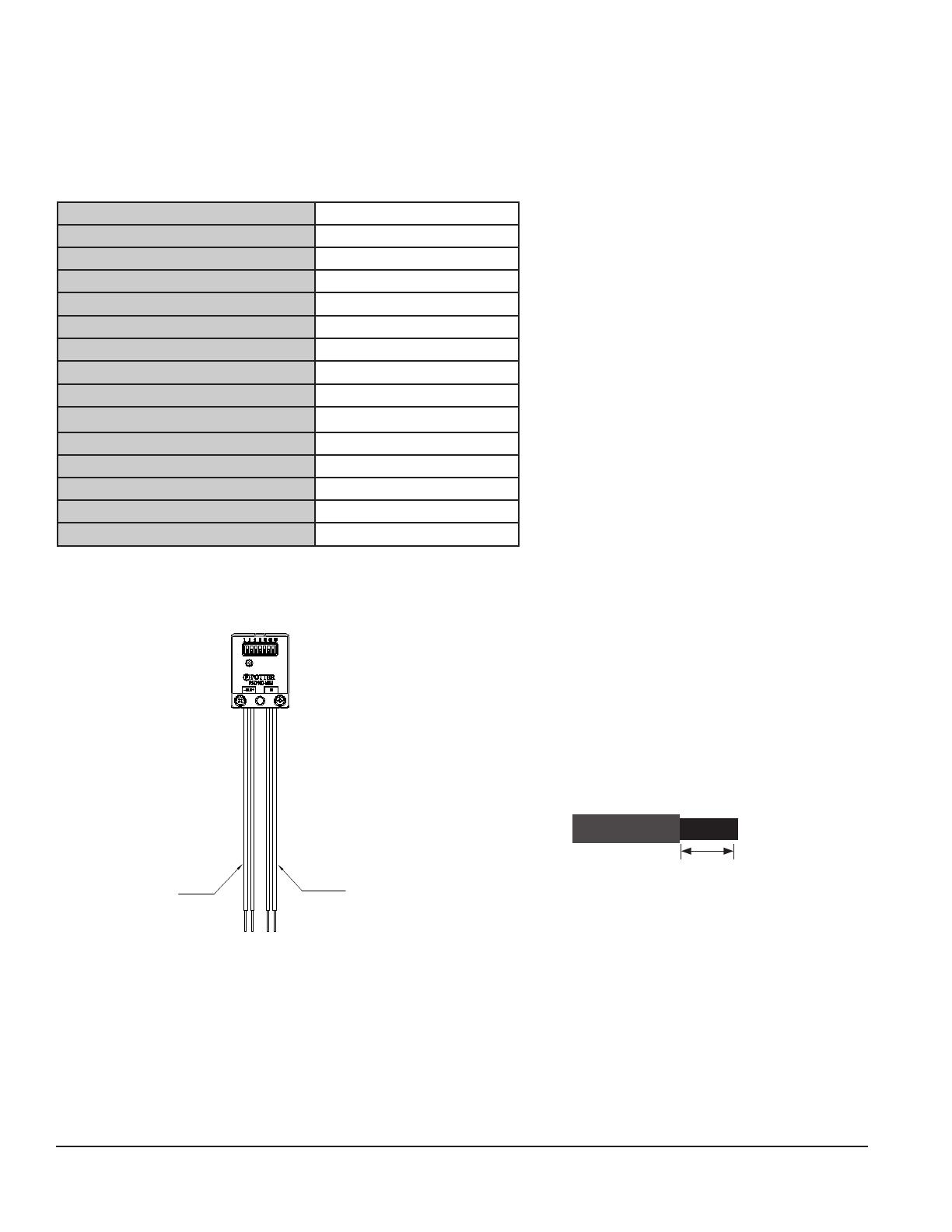
Wire Preparation – Strip all wires 1/4 inch from their edges as
shown here:
– Stripping too much insulation may cause a ground fault.
– Stripping too little may cause a poor connection and
subsequently an open circuit.
1/4 inch
These instructions do not purport to cover all the details or variations in the equipment described, nor provide for every
possible contingency to be met in connection with installation, operation and maintenance.
Specications subject to change without prior notication.
For Technical Assistance contact Potter Electric Signal Company at 866-956-1211.
Actual performance is based on proper application of the product by a qualied professional.
Should further information be desired or should particular problems arise, which are not covered sufciently for the
purchaser's purpose, the matter should be referred to a distributor in your region.
  • Page 1 1
  • Page 2 2

Potter PAD100-MIM User manual

Category
Fire protection
Type
User manual
This manual is also suitable for

Potter PAD100-MIM is a micro input module used for monitoring the status of an initiating device that contains a normally open set of dry contacts. Designed for use with compatible addressable fire systems, it features supervised wiring for terminals SLC+, SLC-, and IN, with a maximum wiring resistance of 100 ohms and capacitance of 1μF on the IDC circuit. The module operates within a voltage range of 24.0V and can withstand temperatures between 32°F and 120°F (0°C to 49°C). Additionally, it has a maximum of 127 units per loop and comes with a 5.1K ohm EOL resistor.

Ask a question and I''ll find the answer in the document

Finding information in a document is now easier with AI