Page is loading ...

Installation Manual: PAD100-ZM Zone Module
NOTICE TO THE INSTALLER
This manual provides an overview and the installation instructions for the PAD100-ZM module. This module is only compatible with
addressable re systems that utilize the PAD Addressable Protocol.
All terminals are power limited and should be wired in accordance with the requirements of NFPA 70 (NEC) and NFPA 72 (National
Fire Alarm Code). Failure to follow the wiring diagrams in the following pages will cause the system to not operate as intended. For
further information, refer to the control panel installation instructions.
The module shall only be installed with listed control panels. Refer to the control panel installation manual for proper system
operation.
1. Description
The PAD100-ZM uses one (1) SLC loop address when monitoring two (2) Class B or one (1) Class A circuit. The module is used to
supervise a zone of conventional 2-wire smoke detectors on an Initiating Device Circuit (IDC). The module requires and supervises
a 24VDC auxiliary power connection. The 24VDC power source must be either a Potter IPA series addressable panel, or a Potter
PSN series power supply. The IDC may be wired as two individual Class B circuits or one Class A circuit which is selectable by an
on board DIP switch. The module mounts on either an UL Listed 2-1/2" deep 2-gang box or 1-1/2" deep 4" square box.
The PAD100-ZM includes one red LED to indicate the module's status. In normal condition, the LED ashes when the device is
being polled by the control panel. When an input is activated, the LED will ash at a fast rate. If the LED blink has been disabled
via the programming software, in a normal condition the LED of the device will be off. All other conditions remain the same.
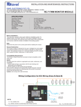
2. Setting the Address
All PAD protocol detectors and modules require an address prior to connection to the panel's SLC loop. Each PAD device's
address (i.e., detector and/or module) is set by changing the dip switches located on the device. PAD device addresses are
comprised of a seven (7) position dip switch used to program each device with an address ranging from 1–127.
Figure 1. PAD Device Dip Switch Addresses Table (Addresses 1–127)
Note: Each "gray" box indicates that the dip switch is "On," and each "white" box indicates "Off."
The examples shown below illustrate a PAD device's dip switch settings: the 1st example shows a device not addressed where all
dip switch settings are in the default "Off" position, the 2nd illustrates an addressed PAD device via the dip switch settings.
Figure 2. Examples of PAD Device Showing Default Dip Switch Setting (Unaddressed) & Addressed PAD Device
Off
On
1 2 4 16
8 32 64 All dip switches are
shown in the "Off"
position. Off
On
1 2 4 16
832 64 Example shows this PAD device's
address = 42. Dip switches #2, 8 &
32 are in the "On" position.
Document 5406308-A 02/16
Potter Electric Signal Company, LLC • St. Louis, MO • Phone: (800) 325-3936 • www.pottersignal.com
PAGE 1 OF 4
1 2 4 8 16 32 64 1 2 4 8 16 32 64 1 2 4 8 16 32 64 1 2 4 8 16 32 64 1 2 4 8 16 32 64
1 27 53 78 103
2 28 54 79 104
3 29 55 80 105
4 30 56 81 106
5 31 57 82 107
6 32 58 83 108
7 33 59 84 109
8 34 60 85 110
9 35 61 86 111
10 36 62 87 112
11 37 63 88 113
12 38 64 89 114
13 39 65 90 115
14 40 66 91 116
15 41 67 92 117
16 42 68 93 118
17 43 69 94 119
18 44 70 95 120
19 45 71 96 121
20 46 72 97 122
21 47 73 98 123
22 48 74 99 124
23 49 75 100 125
24 50 76 101 126
25 51 77 102 127
26 52 1 2 4 8 16 32 64 1 2 4 8 16 32 64 1 2 4 8 16 32 64
1 2 4 8 16 32 64 1 2 4 8 16 32 64
firealarmresources.com

INSTALLATION MANUAL: PAD100-ZM ZONE MODULE
Document 5406308-A 02/16
Potter Electric Signal Company, LLC • St. Louis, MO • Phone: (800) 325-3936 • www.pottersignal.com
PAGE 2 OF 4
When the PAD100-ZM is used to monitor two individual Class B circuits a single device address is assigned; each input is then
identied as a sub-point of the module address. For example, if the address number is assigned as "8", the "B1" input will be "8.1",
and the "B2" input will be "8.2."
Before connecting a device to the SLC loop, take the following precautions to prevent potential damage to the SLC or device.
• Power to the SLC is removed.
• Field wiring on module is correctly installed.
• Field wiring has no open or short circuits.
3. Technical Specications
Operating Voltage 24.0V
Max SLC Standby Current 240 μ A
Max SLC Alarm Current 240 μ A
Aux Power Required 19 – 28V
Max Detector Standby Current of IDC at 24 VDC 1mA
Max Module Alarm Current of IDC at 24 VDC 50mA
Max Wiring Resistance of IDC 100 Ω
Max Wiring Capacitance of IDC 1μF
Smoke Detector Compatibility Identier A
EOL Resistor 5.1K Ω
Operating Temperature Range 32̊ to 120̊ F (0̊ to 49̊ C)
Operating Humidity Range 0 to 93% (non-condensing)
Max no. of Module Per Loop 127 units
Dimensions 4.17" L x 4.17" W x 1.14" D
Mounting Options UL Listed 2-1/2" deep 2-gang box or
1-1/2" deep 4" square box
Shipping Weight 0.6 lbs
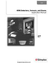
4. Wiring Diagrams
The wiring diagrams shown below illustrate how to wire a PAD100-ZM module as Class A and Class B. Additionally, an installation
diagram shows how to install the module using a compatible electrical box.
Figure 3. Example of Installing a PAD100-ZM Using a Compatible Electrical Box
firealarmresources.com

INSTALLATION MANUAL: PAD100-ZM ZONE MODULE
Document 5406308-A 02/16
Potter Electric Signal Company, LLC • St. Louis, MO • Phone: (800) 325-3936 • www.pottersignal.com
PAGE 3 OF 4
Figure 4. Example of Wiring a PAD100-ZM as Class A
Figure 5. Example of Wiring a PAD100-ZM as Class B
Notes:
• SLC wiring style supports the Class A, Class B and Class X.
• IDC wiring style supports Class A and Class B.
• SLC loop wiring (SLC+, SLC-) and initiating device wiring (B1, B2 and A1) are power limited.
• Wiring for terminals SLC+, SLC- are supervised.
• Wiring for terminals (PWR) are supervised.
• Wiring for terminals (B1, B2 and A1) are supervised.
• All wiring is between #12 (max.) and #22 (min.).
• Wire Preparation – Strip all wires 1/4 inch from their edges as shown here:
– Stripping too much insulation may cause a ground fault.
– Stripping too little may cause a poor connection and subsequently an open circuit.
These instructions do not purport to cover all the details or variations in the equipment described, nor provide for
every possible contingency to be met in connection with installation, operation and maintenance.
Specications subject to change without prior notication.
For Technical Assistance contact Potter Electric Signal Company at 866-956-1211.
Actual performance is based on proper application of the product by a qualied professional.
Should further information be desired or should particular problems arise, which are not covered sufciently for
the purchaser's purpose, the matter should be referred to a distributor in your region.
1/4 inch
FROM FACP OR
PREVIOUS MODULE
TO NEXT MODULE
END-OF-LINE RESISTOR
5.1K OHM
Part #3005013
12W
END-OF-LINE RESISTOR
5.1K OHM
Part #3005013
12W
AUXILIARY 24 VOLT POWER
FROM FACP
+++
---
+++
---
MOVE THE “CL-A” DIP SWITCH
TO “DOWN” POSITION
FOR CLASS B WIRING
FROM FACP OR
PREVIOUS MODULE
TO NEXT MODULE
24 VOLT POWER TO FACP
OR NEXT MODULE
24 VOLT POWER FROM FACP
OR PREVIOUS MODULE
NOTE:
END-OF-LINE RESISTOR
IS NOT REQUIRED
+++
---
MOVE THE “CL-A” DIP SWITCH
TO “UP” POSITION
FOR CLASS A WIRING
firealarmresources.com

INSTALLATION MANUAL: PAD100-ZM ZONE MODULE
Document 5406308-A 02/16
Potter Electric Signal Company, LLC • St. Louis, MO • Phone: (800) 325-3936 • www.pottersignal.com
PAGE 4 OF 4
Table 1: Compatible Conventional Smoke Detectors & Bases
Detector Model Identier Base Model Identier
System Sensor (Brk) (Max. No. Of Detectors Per Zone is 10)
1400 A N/A N/A
2400 A N/A N/A
2400TH AN/A N/A
2W-B A N/A N/A
2WT-B A N/A N/A
Detection System (Max. No. Of Detectors Per Zone is 11)
DS250 A MB2W/MB2WL A
DS250TH AMB2W/MB2WL A
ESL (Max. No. Of Detectors Per Zone is 20)
611U S10 601U S00
611UD S10 601U S00
611UT S10 601U S00
612U S10 601U S00
612UD S10 601U S00
613U5 S10 601U S00
611UD S10 609U10 S00
612UD S10 609U10 S00
425C S10 N/A N/A
425CT S10 N/A N/A
HOCHIKI (Max. No. Of Detectors Per Zone is 20)
SLR-24 HD-3 HSC-221R HB-71
HSB-221 HB-54
HSB-221N HB-54
NS6-221
NS4-221
NS6-220 HB-3
SLR-24H HD-3 HSC-221R HB-71
HSB-221 HB-54
HSB-221N HB-54
NS6-221
NS4-221
SIJ-24 HD-3 HSC-221R HB-71
HSB-221 HB-54
HSB-221N HB-54
NS6-221
NS4-221
FENWAL (Max. No. Of Detectors Per Zone is 14)
CPD-7051 151FE1 2-WIRE FE51A
PSD-7155 P55FE1 2WRLT FE52A
PSD-7156 P56FE1 2WRB FE55A
All of the above Fenwal detectors and bases can be used in any combination.
Retrot Base Adaptor 70-501000-003, Identier MAFE1 (for series 70-201000 Bases, Models -001,-002,-003 and -005).
Duct Housing with Detector Base DN-51, Identier DH22FE5 (for CPD-7051 and PSD-7155 detectors only).
POTTER (Max. No. Of Detectors Per Zone is 25)
PS-24 HD-3 (HOCHIKI) SB-46 HB-71 (HOCHIKI)
HB-54 (HOCHIKI)
SB-93 HB-3 (HOCHIKI)
PS-24H HD-3 (HOCHIKI) SB-46 HB-71 (HOCHIKI)
HB-54 (HOCHIKI)
IS-24 HD-3 (HOCHIKI) SB-46 HB-71 (HOCHIKI)
HB-54 (HOCHIKI)
NOTE: If using a mix of System Sensor and other smoke detectors, a maximum of 20 detectors shall be permitted.
firealarmresources.com
/