Page is loading ...


FFCCCC CCoommpplliiaannccee SSttaatteemmeenntt
This equipment has been tested and found to comply with the limits for a Class B digital device,
pursuant to part 15 of the FCC Rules. These limits are designed to provide reasonable protection
against harmful interference in a residential installation. This equipment generates, uses and can
radiate radio frequency energy and, if not installed and used in accordance with the instructions,
may cause harmful interference to radio communications. However, there is no guarantee that
interference will not occur in a particular installation. If this equipment does cause harmful
interference to radio or television reception, which can be determined by turning the equipment off
and on, the user is encouraged to try to correct the interference by one or more of the following
measures:
• Reorient or relocate the receiving antenna.
• Increase the separation between the equipment and receiver.
• Connect the equipment into an outlet on a circuit different from that to which the
receiver is connected.
• Consult the dealer or an experienced radio/TV technician for help.
UUssee ooff TTrraaddeemmaarrkkss,, RReeggiisstteerreedd TTrraaddeemmaarrkkss,, aanndd ootthheerr PPrrootteecctteedd NNaammeess aanndd SSyymmbboollss
This manual may make reference to trademarks, registered trademarks, and other protected names
and/or symbols of third-party companies not related in any way to StarTech.com. Where they occur
these references are for illustrative purposes only and do not represent an endorsement of a
product or service by StarTech.com, or an endorsement of the product(s) to which this manual
applies by the third-party company in question. Regardless of any direct acknowledgement
elsewhere in the body of this document, StarTech.com hereby acknowledges that all trademarks,
registered trademarks, service marks, and other protected names and/or symbols contained in this
manual and related documents are the property of their respective holders.

Instruction Manual
i
TTaabbllee ooff CCoonntteennttss
Introduction . . . . . . . . . . . . . . . . . . . . . . . . . . . . . . . . . . . . . . . . . . . . . . . . . . . . .1
Features . . . . . . . . . . . . . . . . . . . . . . . . . . . . . . . . . . . . . . . . . . . . . . . .1
System Requirements . . . . . . . . . . . . . . . . . . . . . . . . . . . . . . . . . . . . .1
Package Contents . . . . . . . . . . . . . . . . . . . . . . . . . . . . . . . . . . . . . . . .1
Hardware Guide . . . . . . . . . . . . . . . . . . . . . . . . . . . . . . . . . . . . . . . . . . . . . . . . . .2
Board Layout . . . . . . . . . . . . . . . . . . . . . . . . . . . . . . . . . . . . . . . . . . . .2
Installation . . . . . . . . . . . . . . . . . . . . . . . . . . . . . . . . . . . . . . . . . . . . . . . . . . . . . .5
Hardware Installation . . . . . . . . . . . . . . . . . . . . . . . . . . . . . . . . . . . . . .5
Software Installation . . . . . . . . . . . . . . . . . . . . . . . . . . . . . . . . . . . . . . .5
Configuration . . . . . . . . . . . . . . . . . . . . . . . . . . . . . . . . . . . . . . . . . . . . . . . . . . .6
RS-485 2-wire mode . . . . . . . . . . . . . . . . . . . . . . . . . . . . . . . . . . . . . .6
Baud Rate . . . . . . . . . . . . . . . . . . . . . . . . . . . . . . . . . . . . . . . . . . . . . .7
Application Wiring . . . . . . . . . . . . . . . . . . . . . . . . . . . . . . . . . . . . . . . . .8
Specifications . . . . . . . . . . . . . . . . . . . . . . . . . . . . . . . . . . . . . . . . . . . . . . . . . . .9
Technical Support . . . . . . . . . . . . . . . . . . . . . . . . . . . . . . . . . . . . . . . . . . . . . . . .9
Warranty Information . . . . . . . . . . . . . . . . . . . . . . . . . . . . . . . . . . . . . . . . . . . . .9

Instruction Manual
1
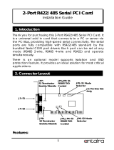
Thank you for purchasing a StarTech.com PCI RS-422/485 Card. This high performance
RS-422/485 multiport serial PCI card works well with two-wire (with Auto Transceiver Turn
Around feature, ATTATM) and four-wire configurations and offers 16C950 compliant
UARTs for broad serial device compatibility.
IInnttrroodduuccttiioonn
•RS-485 mode supports Auto Transceiver Turn Around (ATTA)
Features
BBeeffoorree yyoouu bbeeggiinn
System requirements:
•An IBM compatible computer with a 486 or faster processor (Pentium or higher
recommended)
Package contents:
•1 x Serial PCI Card
This package should contain:
•1 x Instruction Manual
•1 x Driver CD
•Operating systems: Windows 95/98/ME/2000/XP, NT 4.0, Linux
•An available PCI slot
•Easily fits a 3.3V/ 5V PCI and PCI X slot
•PCI 2.2 specification compliant
•128-byte deep FIFO per transmitter and receiver
•High Performance 16C950 UART with maximum data transfer rate up to 921kbps

Instruction Manual
2
HHaarrddwwaarree GGuuiiddee
JP7:S1
Terminator
Enable/Disable
JP1: RS-422/485
Mode Selector
JP5:UART
Clock Speed
Selector
JP8:S2
Terminator
Enable/Disable
Board Layout
JP5: UART Input Clock Speed Selector
UART Input Clock Speed = 1.8432MHz.
Maximum baud rate is 115.2Kbps
Default
setting
UART Input Closk Speed = 14.7456MHz
Maximum baud rate is 926.1Kbps

Instruction Manual
3
HHaarrddwwaarree GGuuiiddee -- ccoonntt’’dd
JP1: RS-422/485 Mode Selector
Jumper Name Jumper Positions Mode and Termination Resistor Setting
485/422
485
(Default) 2-wire RS-485 mode
422 4-wire RS-422 mode
RTS/AUTO
RTS RS-485 Transmitter Buffer Enable is
Controlled by RTS (active high)
AUTO
(Default)
RS-485 Transmitter Buffer is controlled
automatically by ATTATM hardware circuit
ECHO/NO_ECHO
ECHO Transmitting data will be echoed back
NO_ECHO
(Default) No echo data
LOOP/NO_LOOP
LOOP RTS will be connected to CTS
NO_LOOP
(Default) RTS and CTS operate normally
Please note: When set to “422” mode, the other settings (AUTO, ECHO and
LOOP settings) will have no effect.
Echo mode is used to detect data collisions. If the echoed data
was not equal to the transmitted data, then data collisions are
occurring.
If you want to set the RS-485 transceiver to “AUTO” mode, you
must duplicate this setting from the Windows Device Manager. You
only need to perform this step once, as this information will be
retained by Windows.
Please note that S1 and S2 have individual settings, and need to
be configured separately.

Instruction Manual
4
HHaarrddwwaarree GGuuiiddee -- CCoonntt’’dd
S1, S2 Connector Pin Assignments
15
6 9
Pin Signal
1TXD- (DATA-)
2TXD+ (DATA+)
3RXD+
4RXD-
5GND
6 RTS-
7RTS+
8CTS+
9CTS-
S1, S2 Terminator Settings
TXD Terminator
RXD Terminator
RTS Terminator
CTS Terminator
Jumper Name Jumper Settings Termination Resistor Setting
JP7 (TXD) IN TXD Terminator Enabled
OUT (Default) TXD Terminator Disabled
JP7 (RXD) IN (Default) RXD Terminator Enabled
OUT RXD Terminator Disabled
JP7 (RTS) IN RTS Terminator Enabled
OUT (Default) RTS Terminator Disabled
JP7 (CTS) IN(Default) CTS Terminator Enabled
OUT CTS Terminator Disabled
Jumper Name Jumper Settings Termination Resistor Setting
JP8 (TXD) IN TXD Terminator Enabled
OUT (Default) TXD Terminator Disabled
JP8 (RXD) IN (Default) RXD Terminator Enabled
OUT RXD Terminator Disabled
JP8 (RTS) IN RTS Terminator Enabled
OUT (Default) RTS Terminator Disabled
JP8 (CTS) IN(Default) CTS Terminator Enabled
OUT CTS Terminator Disabled
Please note:IN represents that the jumper is installed
OUT represents that the jumper is
not
installed

Instruction Manual
5
IInnssttaallllaattiioonn
WARNING! PCI cards, like all computer equipment, can be severely
damaged by static electricity. Be sure that you are properly grounded before
opening your computer case or touching your card. StarTech.com
recommends that you wear an anti-static strap when installing any computer
component. If an anti-static strap is unavailable, discharge yourself of any
static electricity build-up by touching a large grounded metal surface (such
as the computer case) for several seconds. Also, be careful to handle the
card by its edges and not the gold connectors.
1. Remove the computer cover. For more detailed instruction on how to perform this
step, please refer to the documentation that was included with your computer at the
time of purchase.
2. Locate an empty PCI slot and remove the metal bracket covering the accompanying
empty port/socket.
3. Position the card above the open PCI slot, ensuring that the card is properly aligned
with the slot. Insert the card firmly into the slot, distributing force evenly across the
length of the board. Once inserted, secure the card into the adjoining socket
(previously covered by metal bracket), using the correct size screw.
4. Replace the computer cover and re-connect all power to the computer.
Hardware Installation
Software Installation
The necessary driver files are in ZIP format (e.g. V6515_RS422_485.ZIP) and are
located in E:\IO\OXFORD\RS422_485 (where E: denotes the CD/DVD-ROM drive.
Please copy the file to your local hard drive (presumably C:) and unzip it before
proceeding with installation.
1. When the Found New Hardware Wizard appears, click Next to continue.
2. Select Install from a list or specific location (advanced) and
click Next.
3. Select Include this location in the search and click Browse to
specify the driver’s location.
4. Click Next to continue, then click on Finish to complete installation.
Windows 98, ME, 2000, XP, 2003
Windows NT
Because Windows NT does not support plug and play, you
will need to locate the Install_Serial.exe file (in the
D:\IO\OXFORD\WinNT4 folder), and double click on the
executable file. Follow the prompts to complete installation.

Instruction Manual
6
CCoonnffiigguurraattiioonn
Windows 2000, XP
1. In the PCI Communications Port Properties window, click on the Settings tab.
2. Under Hardware config, select RS422/485, and change the RS485 buffer enable to
Active Low, using the dropdown box provided.
3. Repeat steps 1 and 2 for the remaining port.
Windows 98, ME
1. In the PCI Communications Port Properties window, click on the Settings tab.
2. Change the DTR function to RS485 Buf_En Active high, using the dropdown box
provided.
3. Repeat the steps 1 and 2 to set the remaining port.

Instruction Manual
7
Baud Rate
1. Change the UART input clock jumper (JP5) to HI, as mentioned in the section entitled
JP5: UART Input Clock Speed Selector.
2. Right-click on My Computer and select Manage.
3. Choose Device Manager and double-click on Ports.
4. You will notice the added ports, listed as PCI Communications Port(s). Double-click
on the COM Port you wish to configure, select Data rate, click on Detect Crystal
Frequency, then OK. Repeat this step for the remaining port.
Windows 2000/XP
By default, PCI2S485 is set to a baud rate of 115.2Kbps (maximum). To increase the
baud rate to 921.6Kbps maximum:
Windows 98/ME
1. Change the UART input clock jumper (JP5) to HI, as
mentioned in the section entitled JP5: UART Input
Clock Speed Selector.
2. Right-click on My Computer and select Properties.
3. Choose Device Manager and double-click on Ports.
4. You will notice the added ports, listed as PCI
Communications Port(s). Double-click on the COM
Port you wish to configure, select Data rate, and put
a checkmark next to Detect Crystal Frequency, by
clicking in the box provided. Click on OK to save
this setting. Repeat this step for the remaining port.

Instruction Manual
8
Application Wiring
RS-485 (Transmitter is controlled by ATTATM Hardware)
TXD+ (485)
TXD- (485)
DATA (+)
DATA (-)
2-wire twisted pair cable
Please note that PCI2S485 supports optional auto echo mode operation. When enabled,
data sent to the connected RS-485 transmitter is simultaneously sent to the receiver.
The current application can then use the “echoed” data to check for data collisions.
RS-422 (Transmitter buffer always enabled)
TXD+
TXD-
RXD- (485)
TX+
RX+
TX-
RXD+ (485)
RX-
4-wire twisted pair cable
Please note that PCI2S485 supports 4-wire RS-422 mode, which requires cross-over
twisted pair cable.
PCI2S485 also provides two handshaking signals, RTS+/RTS- and CTS+/CTS- to
perform hardware flow control, which requires the following wiring scheme:
PCI2S485 RS-422 Device

Instruction Manual
9
TTeecchhnniiccaall SSuuppppoorrtt
StarTech.com’s lifetime technical support is an integral part of our commitment to provide
industry-leading solutions. If you ever need help with your product, visit
www.startech.com/support and access our comprehensive selection of online tools,
documentation, and downloads.
WWaarrrraannttyy IInnffoorrmmaattiioonn
This product is backed by a lifetime warranty. In addition, StarTech.com warrants its
products against defects in materials and workmanship for the periods noted, following
the initial date of purchase. During this period, the products may be returned for repair, or
replacement with equivalent products at our discretion. The warranty covers parts and
labor costs only. StarTech.com does not warrant its products from defects or damages
arising from misuse, abuse, alteration, or normal wear and tear.
LLiimmiittaattiioonn ooff LLiiaabbiilliittyy
In no event shall the liability of StarTech.com Ltd. and StarTech.com USA LLP (or their
officers, directors, employees or agents) for any damages (whether direct or indirect,
special, punitive, incidental, consequential, or otherwise), loss of profits, loss of business,
or any pecuniary loss, arising out of or related to the use of the product exceed the
actual price paid for the product. Some states do not allow the exclusion or limitation of
incidental or consequential damages. If such laws apply, the limitations or exclusions
contained in this statement may not apply to you.
SSppeecciiffiiccaattiioonnss
Regulatory Certifications ROHS, FCC, CE
Bus Type 3.3/5V PCI
Connectors 2 x DB9 Male Connectors
Maximum Data Transfer Rate 921kbps
OS Support Windows98/ME/NT/2000/XP/Vista/LINUX
Bits Data Framing Supports 5/6/7/8/9

14 August 2007 (Rev. A)
AAbboouutt SSttaarrTTeecchh..ccoomm
StarTech.com is “The Professionals’ Source for Hard-to-Find Computer Parts”.
Since 1985, we have been providing IT professionals with the quality products
they need to complete their solutions. We offer an unmatched selection of
computer parts, cables, server management solutions and A/V products and
serve a worldwide market through our locations in the United States, Canada, the
United Kingdom and Taiwan.
Visit www.startech.com for complete information about all our products and to
access exclusive interactive tools such as the Parts Finder and the KVM
Reference Guide. StarTech.com makes it easy to complete almost any IT
solution. Find out for yourself why our products lead the industry in performance,
support, and value.
/