Page is loading ...

SCIF XR550DE APPLICATIONS QUICK START GUIDE
LT-1274 © 2022 Digital Monitoring Products, Inc. 22313
4. Mount the Tamper Switches
Mount the two 307-S Tamper Switches in the mounting locations provided
in the enclosure. Connect the two Tamper Switches together in series. Use
the 306 Tamper Harness to connect the Tamper Switches to the XR550DE
Tamper Header. All additional enclosures used must also have tamper
switches installed.
5. Connect AC Power
Caution: Do not apply AC Power to the transformer until all devices are
connected to the panel. See power requirements for SCIFs in ICD 705
for more information.
Connect the transformer wires to panel terminals 1 and 2. Use no more than
70 ft. of 16-gauge, or 40 ft. of 18-gauge, wire between the transformer and
the panel. DMP recommends that all transformer wires from the panel to
the ES502 be installed in conduit to protect them from damage.
If used, mount the ES502 Transformer Enclosure over a dedicated 120VAC
60 Hz outlet not controlled by a switch.
After all components are installed, plug the transformer into the dedicated
120VAC outlet where the ES502 is mounted and close the ES502 cover.
Note: Never share the transformer output with any other equipment.
6. Wire the Batteries
Caution: Observe polarity when connecting batteries. Wire all batteries
in parallel. Ensure all battery harness connectors are fully inserted to
prevent shorting. The panel’s internal battery cuto relay automatically
turns on when the AC transformer is powered.
DMP requires each battery be separated by a PTC in the battery harness
wiring to protect each battery from a reversal or short within the circuit.
DMP recommends that each battery be labeled with the installation date.
1. In the panel enclosure, connect the 14” black battery wire to panel
terminal 4 negative and the 14” red battery wire to panel terminal 3
positive.
2. Plug the 14” red and black battery wires onto the 318 Dual Battery
Harness.
3. Connect the 318 Dual Battery Harness to the two 12V Lead-Acid
Batteries located in the panel enclosure. Observe black and red
polarity on all connections.
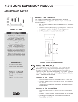
7. Connect Zone Expansion LX-Bus™
Use a DMP model 300 wire harness to connect up to 100 zones using the
LX-Bus on the XR550DE control panel.
The Zone Expansion Bus shall not leave the perimeter of the SCIF. When
possible, all keypads and zone expansion units should be mounted on
interior walls.
8. Connect Network
Use a Standard Ethernet cable with an RJ45 connector and connect one
end of the cable to XR550DE ETHERNET port. Connect the other end of
the Ethernet cable to the Network connection supplied by the Network
Administrator.
The Network LAN/WAN should be powered by a UPS or battery backup
source capable of 24-hour operation should AC power be lost. If not, the
CSA must approve the Network reliability.
Communications between the XR550DE and the remote monitoring facility
with the SCS-1R or SCS-VR Receivers shall be encrypted with the 128 bit or
256 bit (AES) Encryption certified by NIST (National Institute of Standards
and Technology). The DMP NIST certificate number for the 128-bit
XR550DE is 2350 and the DMP NIST certificate for the 256-bit XR550DE is
2595.
SCIF System Information
Before installing any equipment, complete the following section.
Account Number _____________________________________________
Address ____________________________________________________
Phone Number _______________________________________________
Control Panel IP Address _______________________________________
Gateway Address _____________________________________________
Programming Port ____________________________________________
Installation Date ______________________________________________
1. System Components
The system package includes the following components:
• One XR550DEPCB Panel
• One 350A Attack Resistant Enclosure
• Two 307-S Tamper Switches
• One 306 Tamper Harness
• Two Battery(s)
• One 318 Dual Battery Harness
• One 7000 Series Keypad
• One ES502 Transformer Enclosure (optional)
• Additional Components as Required
2. Reference Information
System Grounding
Connect a 14 AWG or larger wire from XR550DE panel terminal 4 to
a good earth ground. DMP recommends a cold water pipe ground,
building ground, or a ground rod. Refer to the NEC (National Electrical
Code) for grounding information. Do not connect to an electrical
ground, conduit, sprinkler or gas pipes, or to a telephone company
ground.
System Wiring
All wiring must be in accordance with NEC. Use non-shielded 22 AWG
wire up to 500 ft. or non-shielded 18 AWG wire up to 1000 ft. from
the panel. Refer to LX-Bus/Keypad Bus Wiring Note (LT-2031) for wire
recommendations.
Reference Documents
As needed during installation, refer to the wiring diagram on the
back, the XR550 Series Installation Guide (LT-1233), XR550 Series
Programming Guide (LT-1232), and any documentation included with the
system components.
Refer ICD 705.1 (Intelligence Community Directive) Chapter 7 Intrusion
Detection Systems (IDS).
Also consult UL 2050 before installing Electronic Security Systems
within a SCIF. Contractors shall comply with UL 2050 by maintaining an
active UL Certificate of Installation and Service.
For arms, ammunition, and explosive (Non-Nuclear) refer to the AA&E
Manual DoD 5100.76-M. All other classified materials are based on the
National Security Program Operating Manual (NISPOM) DoD 5220.22-M.
Caution: Remove All Power! Remove all AC and battery power from
the panel before installing or connecting any modules, cards, or wires.
3. Mount the XR550DE PCB and 350A Enclosure
Mount the 350A enclosure with the XR550DE panel in a secure, dry place
to protect the panel from damage due to tampering or the elements. It is
not necessary to remove the XR550DE PCB when installing the enclosure.
9. Keypad Bus Wiring
Connect the keypad bus wiring to panel terminals 7 through 10. You can
install a maximum of 16 supervised devices on the keypad bus. These can
be keypads and zone expanders. All devices on this bus shall be supervised,
and shall not extend outside the perimeter of the SCIF. When possible, all
keypads and loop expansion shall be mounted on interior walls.
10. Installation Completion
Ensure all devices are properly addressed and all LX-Bus and Keypad
Bus wiring is free of grounds, wire to wire shorts, AC and RF noise, and
induction. Ensure all field devices are properly terminated to the zone
expanders or keypads. All unused wire conductors shall be grounded at
the panel end only so as not to complete a ground loop condition or act
as an antenna. Make note of device circuit wiring to the panel or expansion
modules. This is required when programming the zones to ensure proper
operation.
11. Zone Lay Out
Zones 1-10 are located directly on the XR550DE panel. Keypad Bus
expansion zones are numbered in groups of four corresponding to the
address.
Example: Address #1 is zones 11-14 and address 16 is zones 161-164. There
are a maximum of 64 zones possible on the Keypad Bus.
On the LX-Bus, the first assigned zone numbers are 500-599. If more than
174 zones are needed the XR550DE can be expanded by four more LX-
Buses for a total of 574 zones.
All keypads and zones on the XR550DE system shall be used within the
intended SCIF and for no other purpose.
12. Program the XR550DE
Fill out an XR550DE Programming Sheet (LT-1234) prior to programming
to ensure you have all the necessary information to properly program the
panel. Program the XR550DE panel.
Contractors shall be required to complete the programming sheet and
submit the completed sheet with the accreditation paperwork.
13. Wiring Diagram
The following section illustrates a typical SCIF wiring diagrams.

XR550DE Panel
AC
1 2 3 4 5 6 7 8 10 11 12 13 14 15 16 17 18 199 20 21 22 23 25 26 27 28
+B BELL GND SMK GNDRED YEL GRN BLK Z1 Z2 Z3 Z4 Z5 Z6 Z7
24
Z8 Z9+ Z9– Z10+ Z10–AC –B GND GND GNDGND
RED
YELLOW
GREEN
BLACK
1 2 3 4
9 0 CMD
5 6 7 8
ES502
Transformer
Enclosure
7000 Series
Keypad
Model 350A
Panel Enclosure
Cold Water
Pipe Earth
Ground
307-S
Screw-On
Tamper
Switches
Conduit
3.3k
Ohm
Resistor
Zone
9
Zone
10
SSS S
Zone 3
Zone 4
Zone 5
Zone 6
1k
Ohm
S
S
1k
Ohm
S
S
1k
Ohm
S
S
1k
Ohm
S
S
3.3k
Ohm
Resistor
Zone 7
Zone 8
1k
Ohm
S
S
1k
Ohm
S
S
J6
K
Network to
LAN/WAN
Connection
Zone 1
Zone 2
1k
Ohm
S
S
1k
Ohm
S
S
J4
PTC
318 Battery
Harness
[Write installation date on battery] [Write installation date on battery]
Integrator Supplied
12VDC Battery
Amp/hour to be determined
by load calculation
Integrator Supplied
12VDC Battery
Amp/hour to be determined
by load calculation
Black
RedRed
Black
Black
Red
Panel Black and
Red Wires
1k Ohm
The plug-in transformer
should be plugged into an
outlet not controlled by a
switch.
DMP recommends that all
transformer wiring from
the panel enclosure be
encased in conduit to
protect from damage.
/