Page is loading ...

Installation and user guide
Inverter
3800 TL, 3801 TL, 4300 TL, 4800 TL, 5300 TL, 6300 TL, 7200 TL
As at 10/2013, Material no. 747 405-AD
EN

2
Installation and user guide for PLATINUM® inverters 3800 TL, 3801 TL, 4300 TL, 4800 TL, 5300 TL, 6300 TL, 7200 TL

3
Installation and user guide for PLATINUM® inverters 3800 TL, 3801 TL, 4300 TL, 4800 TL, 5300 TL, 6300 TL, 7200 TL
Contents
1 Introduction 5
1.1 PLATINUM® TL 5
1.2 About this manual 5
1.3 Symbols used 5
1.4 Symbols on product and packaging 6
2 Safety 7
2.1 Intended usage 7
2.2 Improper usage 7
2.3 Personnel requirements 7
2.4 General safety instructions 7
3 Installation 8
3.1 Scope of delivery 8
3.2 Unpacking 8
3.3 Assembly 9
3.4 Connection 13
4 Placing into operation 22
4.1 Switch on 22
4.2 Initial operation 22
4.3 Initial operation menu 23
5 Operation 27
5.1 Display 27
5.2 Operation display 28
5.3 Isolation from the generator field 30
6 Menu 31
6.1 Operate and navigate in the menu 31
6.2 Menu tree 32
6.3 SETTINGS menu 33
6.4 INFORMATION menu 35
6.5 Service menu 36
Contents

4
Installation and user guide for PLATINUM® inverters 3800 TL, 3801 TL, 4300 TL, 4800 TL, 5300 TL, 6300 TL, 7200 TL
7 Maintenance and cleaning 41
7.1 Maintenance 41
7.2 Cleaning 41
8 Errors and troubleshooting 42
8.1 Error display 42
8.2 Event list 44
9 Technical data 48
10 Taking out of operation 52
11 Disposal 53
Contents

5
Installation and user guide for PLATINUM® inverters 3800 TL, 3801 TL, 4300 TL, 4800 TL, 5300 TL, 6300 TL, 7200 TL
Introduction
1 Introduction
1.1 PLATINUM® TL
The inverters in the PLATINUM® TL series are single-phase feed-in inverters for differ-
ent power ranges, see “Technical data” on page 48.
With the aid of the PLATINUM® network (EIA485), up to 50 PLATINUM® inverters can
be connected to form a system.
Options
The following options are available to enhance an inverter or inverter system:
▪ Remote monitoring or remote readouts with the PLATINUM® WebMaster
▪ Evaluation of plant data with the PLATINUM® PV monitor
▪ Remote-controlled AC power reduction via an external monitoring device
1.2 About this manual
This installation and operating manual describes the installation
and operation of the PLATINUM® inverters of the types
3800 TLD, 3801 TLD, 4300 TLD, 4800 TLD, 5300 TLD, 6300 TLD, 7200 TLD.
Additional documents
The following additional documents are available in the download area of our website
www.platinum-nes.com:
▪ Detailed installation and user guide
▪ Information on fault current protection devices
▪ Detailed event list for detecting/eliminating errors
▪ Overview of country and grid codes
▪ Declaration of conformity and certificates
▪ Manufacturer’s warranty
1.3 Symbols used
1.3.1 Structure of warnings
WARNING WORD
Type, source and consequence of the hazard!
f Measures to avoid the hazard.

6
Installation and user guide for PLATINUM® inverters 3800 TL, 3801 TL, 4300 TL, 4800 TL, 5300 TL, 6300 TL, 7200 TL
Introduction
1.3.2 Hazard levels in warnings
Symbol Warning
word
Probability of occurrence Consequences of non-obser-
vance
DANGER Imminent danger Death, serious injury
WARNING Potential danger Death, serious injury
CAUTION Potential danger Minor injury
– CAUTION Potential danger Damage to property
1.3.3 Notes
Notes give tips on how to work easily and safely or contain further infor-
mation.
1.4 Symbols on product and packaging
The following sticker is attached to the inverter:

7
Installation and user guide for PLATINUM® inverters 3800 TL, 3801 TL, 4300 TL, 4800 TL, 5300 TL, 6300 TL, 7200 TL
Safety
2 Safety
2.1 Intended usage
▪ Inverters are to be used solely for the purpose of feeding photovoltaically generated
solar energy into the public grid.
▪ All other usage does not comply with the regulations.
2.2 Improper usage
▪ The inverters are not to be used in off grid PV plants.
▪ The inverters are not to be used in vehicles.
▪ The inverters are not to be used in areas at risk of explosion (flour dust, sawdust, etc.).
▪ The inverters are not to be exposed to direct sunlight.
▪ The inverters are not to be used in areas in which the ammonia content of the air
exceeds 20 ppm.
▪ All warranty claims will be rendered null and void in the event of failure to comply
with the warranty terms or the information provided in this operating and installation
manual.
2.3 Personnel requirements
The inverter may only be installed and put into operation in accordance with this
installation and user guide by trained specialist personnel, for example:
▪ Service partners authorised by PLATINUM GmbH
▪ Authorised specialist personnel with knowledge of the applicable guidelines and
standards
2.4 General safety instructions
▪ The inverters are to be used in their original state without independent modifications
and in a technically perfect condition.
▪ Steps must be taken to ensure that the following are adhered to when assembling
and connecting the inverter and the PV system:
– Guidelines and regulations valid in the respective country
– Provisions of the trade associations, TÜV, VDE (Association for Electrical, Electronic
& Information Technologies)
– Technical connection conditions of the energy supplier responsible
– National and international regulations and provisions
▪ Ensure that all protection devices are working correctly.
▪ Observe the operating conditions; see “Technical data” on page 48.

8
Installation and user guide for PLATINUM® inverters 3800 TL, 3801 TL, 4300 TL, 4800 TL, 5300 TL, 6300 TL, 7200 TL
Installation
3 Installation
3.1 Scope of delivery
▪ Inverter
▪ Wall bracket
▪ Brief guide
3.2 Unpacking
CAUTION
The inverter is heavy!
f Ask another person to help you unpack and lift it.
f Wear safety shoes when unpacking the inverter and during
installation.
f Ensure that the inverter is positioned securely.
3.
4.
5.
2
1
1. Place the box upright (note the
lettering on the box).
2. Cut the retaining straps without
damaging the box.
3. Grab the handle openings (1) on the
outer jacket of the box and lift it up
and off.
4. Take off the cover from the box.
5. Lift the inverter by the handle
openings (2) out from the bottom of
the box.
6. Set down the inverter.
The supplied brief guide is located underneath the protector; see 13.

9
Installation and user guide for PLATINUM® inverters 3800 TL, 3801 TL, 4300 TL, 4800 TL, 5300 TL, 6300 TL, 7200 TL
Installation
3.3 Assembly
3.3.1 Safety instructions
WARNING
Injury may result if the inverter falls!
f Use fixing materials suited to the assembly wall and the weight of the
inverter.
f Get a second person to help with assembly and disassembly.
f Wear safety shoes during assembly and disassembly.
f Ensure that the inverter is positioned securely.
CAUTION
Material damage due to excessive build-up of dust!
The protection class IP66 does not apply to the communication interface.
f Avoid excessive build-up of dust.
f Avoid build-up of dust with electrically conductive dust particles.
In order to comply with the requirements of standard IEC-62109, a
possibility must be provided for tool-free isolation of the solar generator.
If the design does not feature an integrated DC isolator then an external
isolation device is mandatory; this must be easily accessible.
PLATINUM GmbH recommends that the inverter should not be installed
in living quarters.

10
Installation and user guide for PLATINUM® inverters 3800 TL, 3801 TL, 4300 TL, 4800 TL, 5300 TL, 6300 TL, 7200 TL
Installation
3.3.2 Disassemble the wall bracket from the inverter.
4
3
1. Loosen but do not remove the safety
screws on the sides (3).
2. Grab the wall bracket (4) at the bottom
and lift it up off the inverter.

11
Installation and user guide for PLATINUM® inverters 3800 TL, 3801 TL, 4300 TL, 4800 TL, 5300 TL, 6300 TL, 7200 TL
Installation
3.3.3 Mounting the inverter
The upper cutout in the wall bracket corresponds to the position of the
display and buttons on the mounted inverter.
≥191
≥177
Ø9
≥500
344
125125
≥232
115
≥494
≥920
285
Dimensions in mm
1. Choose a suitable location for assembly. Take into account dimensions and
distances.
2. Fix the wall bracket to the assembly wall with suitable fixing materials.

12
Installation and user guide for PLATINUM® inverters 3800 TL, 3801 TL, 4300 TL, 4800 TL, 5300 TL, 6300 TL, 7200 TL
Installation
3
5
5
3
3
4
5
1. Working from underneath, hook the
hanger of the inverter (5) at the top in
the slotted piece of the wall bracket
(4).
2. Ensure that the inverter is fitted
correctly on the wall bracket.
3. Secure the inverter by tightening the
safety screws (3) on the sides.

13
Installation and user guide for PLATINUM® inverters 3800 TL, 3801 TL, 4300 TL, 4800 TL, 5300 TL, 6300 TL, 7200 TL
Installation
3.4 Connection
3.4.1 Preparatory work
On devices with a DC disconnect
t Move the switch knob of the DC
disconnect on the underside of the
device to the “0” position.
On devices without a DC disconnect
t Disconnect the DC voltage side with
the external isolation device from the
solar generator.
6
7
1. Grab the protector (6) by its underside
and pull it off the inverter.
2. Take out the brief guide (7).
3. Hang the protector in one of the
holders on the sides of the inverter.

14
Installation and user guide for PLATINUM® inverters 3800 TL, 3801 TL, 4300 TL, 4800 TL, 5300 TL, 6300 TL, 7200 TL
Installation
3.4.2 Connect the AC voltage
DANGER
Risk of death due to high AC voltage!
f Switch off the mains voltage supply (AC side) before connecting the
inverter (safety device).
f Make sure that the central isolation device can be accessed freely.
f Only connect the inverter to TN or TT networks (see IEC 60364-1) with
230 V.
f Observe max. fuse protection permitted on the AC voltage side, see
“Technical data” on page 48.
f Make the AC voltage connection with a cable isolator switch.
PLATINUM GmbH recommends a type C cable isolator switch.
f If an external residual current protective device is required, PLATINUM
GmbH recommends using a residual current protective device (RCD)
of type A.
CAUTION
Destruction of the inverter!
f Never connect inverters between two phases.
f Never mix up the phases with PE or N.
f Distribute the inverters across the three phases in such a way that the
differences between the AC power levels on the different phases do
not exceed the maximum permitted unbalanced load of the network
operator.
Prepare the connection cable for the AC voltage
Dimensioning the wire cross section is the responsibility of the
electrician and depends on the cable length and installation situation.
▪ Min. cross section 4 mm
2
▪ Max. cross section 16 mm
2
1. Protect the AC voltage connection lines with appropriate fuses, see “Technical data”
on page 48.
2. Strip 18 mm of insulation from the AC voltage connection lines and add wire-end
sleeves.

15
Installation and user guide for PLATINUM® inverters 3800 TL, 3801 TL, 4300 TL, 4800 TL, 5300 TL, 6300 TL, 7200 TL
Installation
Connect
8
1. Take off the cover (8) from the AC
voltage connection by removing
4 screws.
2. Put the screws in the row of holes.
3. Unfasten the AC screw connection (9)
with seal from the underside of the
inverter.
The cable entry is sealed with a thin
protective layer (10) against external
influences. This protective layer needs to
be removed.
4. Direct the prepared AC voltage
connection line through the AC screw
connection and seal.
5. Feed the AC voltage connection line
into the housing from below.
6. Tighten the AC screw connection.

16
Installation and user guide for PLATINUM® inverters 3800 TL, 3801 TL, 4300 TL, 4800 TL, 5300 TL, 6300 TL, 7200 TL
Installation
L N PE 1 2
LNPE 12
7. Connect the AC voltage connection
cable to the inverter:
– Open the terminal with a
screwdriver.
– Insert the conductor.
– Remove the screwdriver.
Terminal Assignment
L Feed phase L1
N Neutral
PE Potential equalisation
1 Monitoring phase L2,
for 3-phase ENS only
2 Monitoring phase L3,
for 3-phase ENS only
8. Refit the cover of the AC voltage
connection using the 4 screws
3.4.3 Connect DC voltage
DANGER
Risk of death due to high DC voltage! A voltage is present at the
PV modules when it is bright.
f Before connecting the inverter, check whether voltage is applied to
the generator’s DC voltage connection.
f Before connecting the inverter, check whether the polarity of the
DC voltage is correct.
f If voltage is applied, wear insulating protective clothing and face
protection.
f Ensure that the cable plug has engaged completely with the socket.
f Detach the DC voltage cable only if the inverter is not in operation.
f Make sure that the DC isolator or a central isolation device can be
accessed freely.
f Do not ground the poles of the PV modules. The inverter does not
have a transformer.

17
Installation and user guide for PLATINUM® inverters 3800 TL, 3801 TL, 4300 TL, 4800 TL, 5300 TL, 6300 TL, 7200 TL
Installation
WARNING
Risk of electric shock and material damage!
f Use only the original DC voltage Multi-Contact MC4 cable plug.
f Only connect PV modules that meet the requirements of
IEC 61730 class A.
f Ensure that the max. DC voltage permitted is not exceeded.
f Ensure that the max. direct current permitted per string is not
exceeded.
If more than one string is connected, make sure that the quantity and
type of solar modules and the voltage of strings to be connected in
parallel are the same.
–
+
–
+
1. Fit original Multi-Contact MC4 connec-
tors to each string of the DC voltage
cable. Make sure that the polarity is
correct here.
2. Take off the protective caps from the
required DC voltage connections.
3. Insert the prepared DC voltage
connectors into the DC voltage
connections. In the process, make
sure that the connectors lock in place
correctly.
Fit protective caps to plug connectors that are not used on the inverter.

18
Installation and user guide for PLATINUM® inverters 3800 TL, 3801 TL, 4300 TL, 4800 TL, 5300 TL, 6300 TL, 7200 TL
Installation
3.4.4 Connection to the PLATINUM® network (EIA 485)
Up to 50 PLATINUM® inverters can be connected with monitoring
devices into a network with an overall length of up to 1000 m.
Network cable
▪ CAT 5 shielded twisted pair cable with pre-assembled RJ45 plugs (pin 3 = B and
pin 6 = A)
– or –
▪ Twisted pair of wires of a CAT 5 cable
Connect
11
1. Take off the cover (11) from the termi-
nal strip.

19
Installation and user guide for PLATINUM® inverters 3800 TL, 3801 TL, 4300 TL, 4800 TL, 5300 TL, 6300 TL, 7200 TL
Installation
shield
EIA 485
12
EIA 485
A
B
A
B
0 V
+ 12 V / max. 30
N.C.
optional Input (m
24V
2. Connect the network cables in the
inverter.
CAT 5 cable with RJ45 plug
▪ Incoming cable: Socket 1
▪ Outgoing cable: Socket 2
CAT 5 cable with 2 twisted wires
▪ Incoming cables:
Left-hand terminals A, B
▪ Outgoing cables:
Right-hand terminals A, B
▪ Shielding: Shield
t Ensure that signal lines A and B are
not connected incorrectly.
Termination
An integrated terminating resistor can be activated at both open ends of the network (at
the first and last inverters).
Terminating ensures that the network functions correctly.
12
1. Remove the terminating plug (12)
from the protector.
2. Connect the terminating plug to
socket 1 of the first and last inverter.

20
Installation and user guide for PLATINUM® inverters 3800 TL, 3801 TL, 4300 TL, 4800 TL, 5300 TL, 6300 TL, 7200 TL
Installation
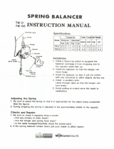
3.4.5 Further connections on the terminal strip
On the terminal strip, there are further terminals for the connection of a potential-free
alarm contact, an external consumer and an input.
shield
A
B
A
B
0 V
+ 12 V /
N.C.
optional
1234567
(1) Alarm contact (NC contact)
(2) Alarm contact (centre contact)
(3) Alarm contact (NO contact)
(4) Not used
(5) Input, 12 V max. (optional)
(6) Supply voltage for external
consumer, 12 V, 300 mW max.
(7) Supply voltage for external
consumer, 0 V
Alarm contact
In the event of a fault, the contact closes and activates the alarm system (visual or
acoustic) if required.
t For the supply voltage, only use a safety extra-low voltage (SELV) with a maximum
voltage of 24 V.
The alarm contact can be configured in the menu
SETTINGS –> ALARM FUNCTION; see 34.
/