
ISDN DEFINITY Extender
Models 2300EU and 2100EU
System Administrator’s Guide
Document: 555-025-118
Comcode: 108478421
Issue 1
February 1999

Copyright 1999, Lucent Technologies Issue 1
All Rights Reserved February 1999
Printed in USA
Notice
Every effort was made to ensure that the information in this book was complete and accurate at
the time of printing. However, information is subject to change.
Your Responsibility for Your System’s Security
Toll fraud is the unauthorized use of your telecommunications system by an unauthorized party,
for example, persons other than your company’s employees, agents, subcontractors, or persons
working on your company’s behalf. Note that there may be a risk of toll fraud associated with
your telecommunications system and, if toll fraud occurs, it can result in substantial additional
charges for your telecommunications services.
You and your system manager are responsible for the security of your system, such as program-
ming and configuring your equipment to prevent unauthorized use. The system manager is also
responsible for reading all installation, instruction, and system administration documents pro-
vided with this product in order to fully understand the features that can introduce risk of toll
fraud and the steps that can be taken to reduce that risk. Lucent Technologies does not warrant
that this product is immune from or will prevent unauthorized use of common-carrier
telecommunication services or facilities accessed through or connected to it. Lucent
Technologies will not be responsible for any charges that result from such unauthorized use.
Lucent Technologies Fraud Intervention
If you suspect that you are being victimized by toll fraud and you need technical support or assis-
tance, call your local Lucent representative.
Federal Communications Commission Statement
This equipment has been tested and found to comply with the limits for a Class A digital device,
pursuant to Part 15 of the FCC Rules. These limits are designed to provide reasonable protection
against harmful interference when the equipment is operated in a commercial environment. This
equipment generates, uses, and can radiate radio frequency energy and, if not installed and used
in accordance with the instruction manual, may cause harmful interference to radio communica-
tions. However, there is no guarantee that interference will not occur in a particular installation.
For further FCC information, see "Customer Support Information" below.
Ordering Information
For more information about Lucent Technologies documents, refer to the section entitled
“Related Documents” in “About this Guide.”
Outside the USA, if you need assistance when installing, programming, or using your system,
contact your Lucent Technologies authorized representative.
Support Telephone Number
Contact your local Lucent Technologies representative.

Table Of Contents
ISDN DEFINITY
Extender 2300EU/2100EU
About this Guide......................................................... 1
Introduction......................................................................................1
Prerequisite ......................................................................................1
Product Overview....................................................... 2
Introduction......................................................................................2
Product Family.................................................................................3
How the Connection Works............................................................4
Checklist...................................................................... 5
Introduction......................................................................................6
Switch Module Checklist.................................................................7
ISDN Line Checklist........................................................................8
PC or Network Connection.............................................................5
Environment Checklist....................................................................9
Electrical Checklist..........................................................................9
Quick Configuration Guide..................................... 10
Introduction....................................................................................10
Configuring and Installing the Switch Module...........................10
Verifying Configuration................................................................13
Powering Up/ Down.......................................................................13

Table Of Contents
ISDN DEFINITY
Extender 2300EU/2100EU
Configuring Using a Terminal.................................14
Introduction................................................................................... 14
Requirements................................................................................. 14
The ETI and TTI Menus............................................................... 15
Accessing ETI/TTI Menu ............................................................. 15
Terminal Edit Line........................................................................ 16
Configuring The Switch Module.................................................. 17
Setting ISDN Parameters.............................................................. 18
Setting DN1.................................................................................. 16
Setting DN2.................................................................................. 17
Setting the TEI Type..................................................................... 18
Saving ISDN Changes .................................................................. 22
System Menu ................................................................................ 22
Passwords ..................................................................................... 22
Configuring the COM Port.......................................................... 23
Setting Data Rate ......................................................................... 21
Setting Parity ................................................................................ 21
Setting Data Bits........................................................................... 21
Setting Stop Bits........................................................................... 22
Show Settings ............................................................................... 25
Software Upgrades........................................................................ 25

Table Of Contents
ISDN DEFINITY
Extender 2300EU/2100EU
Data Communications.............................................. 26
Introduction....................................................................................26
Using the RS232C COM Port.......................................................27
9 Pin RS232C Connector ..............................................................28
Hardware Flow Control.................................................................28
2100EU Terminal Information............................... 29
Introduction....................................................................................29
Description......................................................................................29
Typical Connections......................................................................29
Typical Operation .........................................................................30
Setting the PC Modem..................................................................31
2100EU TA Configuration ...................................... 32
Introduction....................................................................................32
Changing Terminal Adapter Settings..........................................32
Setting the Data Rate.....................................................................32
Setting Parity.................................................................................33
Setting Data Bits ...........................................................................33
Setting Stop Bits............................................................................33

Table Of Contents
ISDN DEFINITY
Extender 2300EU/2100EU
2100EU AT Command Set .......................................34
Introduction................................................................................... 34
Terminal Adapter Configuration Commands............................ 36
Terminal Adapter Action Commands......................................... 39
AT Result Codes............................................................................ 39
Software Upgrading..................................................41
Introduction................................................................................... 41
Obtaining the Upgrade File.......................................................... 41
Upgrading the Serial Port............................................................. 40
Verify Upgrade.............................................................................. 44
Upgrading from the Remote Module .......................................... 45
Verifying the Switch Upgrade...................................................... 47

Table Of Contents
ISDN DEFINITY
Extender 2300EU/2100EU
Troubleshooting........................................................ 48
Introduction....................................................................................48
No Remote Site Phone Display .....................................................48
No Switch Module Connection .....................................................49
No Indicator Lights at Power Up.................................................49
Switch Module Will Not Answer.................................................49
LED Sequences...............................................................................50
LED Power Up Sequences............................................................50
LED Power Up Verification Sequences........................................50
LED Error Indicator Sequences....................................................51
Serial S-Record Upgrade Errors....................................................53
Cannot Upgrade Software.............................................................53
Upgrade Failed..............................................................................53
ISDN Upgrade Errors....................................................................53
PBX Flash Too Small....................................................................53
REM Flash Too Small...................................................................53
Upgrade Start Failure....................................................................54
Flash Erase Failure........................................................................54
Flash V Erase Failure....................................................................54
UG Data Timeout Failure..............................................................54
Data End Timeout Failure.............................................................54
UG CRC Timeout Failure .............................................................54
Diagnostic Statistics.......................................................................55
Error Codes ...................................................................................52
Exclusive Error Codes...................................................................57
Resetting the Statistics..................................................................58
Connection Errors .........................................................................54
Fatal Errors....................................................................................65
Customer Support Information....................................................66


ISDN DEFINITY
Extender 2300EU/2100EU
1
About This Guide
Introduction
The ISDN DEFINITY
Extender 2300EU/2100EU
System Administrator’s Guide provides you with
information to:
•
Install
•
Configure
•
Operate
•
Troubleshoot
Prerequisite
This manual was written with the assumption that you
possess a working knowledge of Lucent digital phones
and the DEFINITY
Enterprise Communications System
(ECS).
Should you require further information on how the phone
or ECS works, we suggest you either consult your Lucent
Technologies system administrator, or read the user
documentation provided with your phone system.

ISDN DEFINITY
Extender 2300EU/2100EU
2
Product Overview
Introduction
The Lucent Extender series provides remote workers and
small branch offices seamless connectivity to the
DEFINITY
ECS in addition to the corporate LAN.
Remote employees can: place and receive calls through
the ECS; use three-digit internal dialing; transfer calls; set
up conference calls; have a corporate-based receptionist
screen calls; access the voice mail, auto-attendant or any
other software residing on the ECS. Extenders work with
existing corporate, digital telephone sets, but there are
restrictions to telephone use at residential locations.
Transmission is over the public telephone network using
ISDN, or BRI lines.
A Switch Module and a Remote Module are all that is
needed to provide an off-premise employee with full
voice and data communications functionality.

ISDN DEFINITY
Extender 2300EU/2100EU
3
Product
Family
The ISDN DEFINITY
Extender, Models 2300EU and
2100EU, extends a DEFINITY
ECS to a remote site by
using a Switch and a Remote Module, over one ISDN B-
channel.
The connection to the ISDN network is done via the built-
in S/T interface. The Switch Module connects to a digital
port on the ECS located at the corporate office, and the
Remote Module connects to a Lucent digital phone set at
a remote location.
The ISDN DEFINITY
Extender, Models 2300EU and
2100EU, includes MCK’s Interactive Voice Protocol
TM
software. The software packetizes, compresses, and
encrypts voice and ECS signals to condition them for
transmission over a public, circuit-switched network.

ISDN DEFINITY
Extender 2300EU/2100EU
4
Product Overview
Product
Family cont’d
Other features of the ISDN DEFINITY
Extender,
Models 2300EU and 2100EU, include: an available
analog port* and an RS232 terminal connection,
depending on the model ordered.
*Note: Analog port available on the Remote Module
only.
How the
Connection
Works
The Switch Module and the Remote Module
communicate by transmitting signals across a single
ISDN B channel. The B channel establishes a 64 Kbps
digital link.
The second B channel will have one of the following
capabilities, depending on the model you have:
2300EU – Analog Port*
2100EU – Analog Port* & RS232 Terminal
Adapter
*Note: The Analog Port is only available on the Remote
Module.
Speech is compressed to 32 Kbits ADPCM format and is
combined with the telephone signaling data and COM
port data for 2300EU. Once the installation has been
completed, your Remote Module will enable your
remotely located Lucent phone to function exactly like
your deskset at the office.
For instructions about using a Lucent phone, refer to the
documentation provided with your phone.

ISDN DEFINITY
Extender 2300EU/2100EU
5
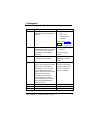
Compatbility
The DEFINITY Extender
is compatible with the
following commercial two-wire DEFINITY ECS
display telephones.
■
6408D + (This display telephone is certified for
residential use.)
■
6416D+ (This display telephone is certified for
residential use.)
■
6424D+ (This display telephone is certified for
residential use.)
■
8410D
■
8410DR (This display telephone is certified for
residential use.)
■
8434D (Requires a separate power supply.)
NOTE:
The power supply that comes with the ISDN
Remote Module cannot produce the power required
by the 8434D telephone. An MSP-1 (WP924644)
power supply must be used. Check with your Lucent
Technologies representative for ordering
information.
■
603 E Callmaster III
®
■
603F1 Callmaster IV
■
Callmaster VI
®
(This PC-based product is
certified for residential use.)
NOTE:
For residential installations, FCC regulations
prohibit use of telephones not certified for
residential use.

ISDN DEFINITY
Extender 2300EU/2100EU
6
Checklists
Introduction
Before continuing with the installation and configuring of
your Switch Module, please go through the following
checklists.

ISDN DEFINITY
Extender 2300EU/2100EU
7
Switch
Module
Checklist
Your ISDN DEFINITY
Extender, Models 2300EU and
2100EU, Switch Module package should contain:
❑ One ISDN DEFINITY
Extender, Models 2300EU
and 2100EU, Switch Module.
❑ One ISDN DEFINITY
Extender, Models 2300EU
and 2100EU, System Administrator’s Guide.
❑ One 220 or 240 volt AC adapter.
❑ One RJ45 line cord.
The following services should be installed and tested
before proceeding:
❐ DEFINITY
ECS digital port.
❐ DEFINITY
ECS BRI port or ISDN line, as described
in the ISDN line checklist.
Parts required to configure the Switch Module, but NOT
included with the system:
❐ PC or terminal with a terminal emulation package
(must be VT100 compatible).
❐ RS232 serial cable. (Male DB9 connector required to
connect to the Switch Module. The other connector
should match to the PC or terminal.)
❐ RJ45 cable.

ISDN DEFINITY
Extender 2300EU/2100EU
8
Checklists
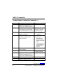
ISDN Line
Checklist
The recommended ISDN line provisioning is:
❐ ETSI Net 3 with 2 DNs and Auto TEI type.
❐ Circuit Switched Voice and Data on both B channels
(B1 and B2).
❐ No call features are required on any B channels.
❐ Must be capable of 56K or 64k Synchronous Data
Calls, Clear Channel
NOTE:
Specifications are subject to change without
notice as technological or manufacturing changes warrant.
❑ Ensure you have the proper ISDN line installed at the
switch site.
❑ Ensure you know the DN numbers and TEI type. You
obtain this information from your local ISDN service
provider when the ISDN lines are installed.
❑ Ensure that you have registered the ISDN lines with
your long distance carrier for ISDN DATA Service, if
required.
PC or
Network
Connection
If you are connecting ISDN DEFINITY
Extender,
Models 2300EU and 2100EU, Switch Module to a PC
or network , you will require:
For the model 2300EU or 2100EU:
❐ One serial cable with a male DB9 cable end.

ISDN DEFINITY
Extender 2300EU/2100EU
9
Checklists
Environment
Checklist
The installation area should be:
❑ Well ventilated and free of dust.
❑ Have an ambient temperature of 0ºC (32ºF) to 55ºC
(131ºF), with a relative humidity below 95%.
❑ Free of any large electrical equipment such as copiers
or motors that generate electromagnetic, radio
frequency, and electrostatic interference.
❐ Within 150 meters (500 feet) of the DEFINITY
ECS.
Electrical
Checklist
The AC electrical requirement for the ISDN DEFINITY
Extender, Models 2300EU and 2100EU, is:
❑ 12 volt DC unregulated supplied by 220 or 240 Volt
adapters.

ISDN DEFINITY
Extender 2300EU/2100EU
10
Quick Configuration
Introduction
This section provides step-by-step procedures to
configure your Switch Module.
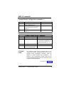
Configuring
and
Installing the
Switch
Module
Ensure that you have the Switch Module (module is
labeled ‘Switch Module’ on the cover) before proceeding.
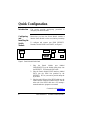
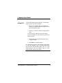
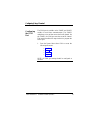
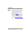
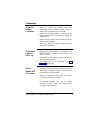
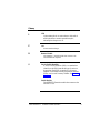
To configure and connect your ISDN DEFINITY
Extender, Models 2300EU and 2100EU, see Figure 1:
Figure 1. Switch Module Back Panel
1. Plug the Switch Module port (labeled
PHONE/SWITCH on the Module back plane) into
the DEFINITY
ECS using the RJ45 cable.
2. Plug the Switch Module ISDN interface (labeled
ISDN) into the ISDN line provided by the
DEFINITY
ECS or your service provider using the
RJ45 cable.
3. Plug the male DB9 end of the RS232 cable into the
Switch Module connector (labeled RS232) and the
other end of the RS232 cable into a PC running a
terminal emulation program or a terminal.
Continued on the next page…
PHONE/
SWITCH
RS-232 ISDN +12VDC

ISDN DEFINITY
Extender 2300EU/2100EU
11
Quick Configuration
Configuring
And
Installing
The Switch
Module cont’d
The RS232 parameters default at 9600 bps, 8 data
bits, 1 stop bit, and no parity and use VT100 terminal
emulation mode.
4. Plug in the 220/240 volt AC adapter provided with
the Switch Module.
The Module’s LED will start flashing and performing
the power-up test.
The Module’s LED will perform a series of yellow,
green and red blinks. After 10 seconds of very fast
red blinking, the LED will blink green three times
and red once. The LED will then blink 3 sets of 8
yellow flashes.
NOTE: You can only access the menu on power up.
5. During this yellow flash sequence type the word
MENU.
After you have entered the command, the Switch
Configuration menu will appear on the terminal program.
6. Select Configure ISDN to configure the following
ISDN parameters:
•
The ISDN network switch type. Currently only
ETSI NET 3 is available.
•
The DN1 and DN2 numbers for the Switch ISDN
line.
•
TEI type (auto, fixed).
•
TEI1 if fixed TEI type was selected.
Continued on the next page…

ISDN DEFINITY
Extender 2300EU/2100EU
12
Quick Configuration
Configuring
And
Installing
The Switch
Module cont’d
These parameters must be supplied by the ISDN service
provider that installed your ISDN line. If no TEI
information was supplied, use the auto TEI mode.
7. Write down the Switch DN1 number to use later
when programming the Remote Module. This DN1
number will be entered in the Remote Module under
the menu Set PBX Number.
If you are using the Switch Module for your data
connection, write down the DN2 number. You will
need it to program your remote data equipment.
8. After the ISDN parameters are entered, exit the
Configure ISDN menu.
You will be prompted to save the new ISDN
parameters.
9. Select Yes. The Switch Module will initialize to the
ISDN network at this time.
Access the Configure System menu from the Main
menu.
10. Set Passwords, if required.
11. Set the COM port, if required.
12. Set ISDN Connect Rate, if required.
13. Select the Show Settings menu to confirm all
parameters were entered correctly.
14. Select Exit.
15. Select Exit again to end the programming session.
Page is loading ...
Page is loading ...
Page is loading ...
Page is loading ...
Page is loading ...
Page is loading ...
Page is loading ...
Page is loading ...
Page is loading ...
Page is loading ...
Page is loading ...
Page is loading ...
Page is loading ...
Page is loading ...
Page is loading ...
Page is loading ...
Page is loading ...
Page is loading ...
Page is loading ...
Page is loading ...
Page is loading ...
Page is loading ...
Page is loading ...
Page is loading ...
Page is loading ...
Page is loading ...
Page is loading ...
Page is loading ...
Page is loading ...
Page is loading ...
Page is loading ...
Page is loading ...
Page is loading ...
Page is loading ...
Page is loading ...
Page is loading ...
Page is loading ...
Page is loading ...
Page is loading ...
Page is loading ...
Page is loading ...
Page is loading ...
Page is loading ...
Page is loading ...
Page is loading ...
Page is loading ...
Page is loading ...
Page is loading ...
Page is loading ...
Page is loading ...
Page is loading ...
Page is loading ...
Page is loading ...
Page is loading ...
Page is loading ...
Page is loading ...
Page is loading ...
Page is loading ...
Page is loading ...
Page is loading ...
-
 1
1
-
 2
2
-
 3
3
-
 4
4
-
 5
5
-
 6
6
-
 7
7
-
 8
8
-
 9
9
-
 10
10
-
 11
11
-
 12
12
-
 13
13
-
 14
14
-
 15
15
-
 16
16
-
 17
17
-
 18
18
-
 19
19
-
 20
20
-
 21
21
-
 22
22
-
 23
23
-
 24
24
-
 25
25
-
 26
26
-
 27
27
-
 28
28
-
 29
29
-
 30
30
-
 31
31
-
 32
32
-
 33
33
-
 34
34
-
 35
35
-
 36
36
-
 37
37
-
 38
38
-
 39
39
-
 40
40
-
 41
41
-
 42
42
-
 43
43
-
 44
44
-
 45
45
-
 46
46
-
 47
47
-
 48
48
-
 49
49
-
 50
50
-
 51
51
-
 52
52
-
 53
53
-
 54
54
-
 55
55
-
 56
56
-
 57
57
-
 58
58
-
 59
59
-
 60
60
-
 61
61
-
 62
62
-
 63
63
-
 64
64
-
 65
65
-
 66
66
-
 67
67
-
 68
68
-
 69
69
-
 70
70
-
 71
71
-
 72
72
-
 73
73
-
 74
74
-
 75
75
-
 76
76
-
 77
77
-
 78
78
-
 79
79
-
 80
80


Lucent Technologies 2100EU System Administrator Manual
- Type
- System Administrator Manual
- This manual is also suitable for
Ask a question and I''ll find the answer in the document
Finding information in a document is now easier with AI
Related papers
-
Lucent Technologies 555-230-796 User manual
-
-
Lucent Technologies Definity Callmaster II Programming The Options
-
Lucent Technologies MERLIN LEGEND Release 5.0 User manual
-
-
-
-
-
-
Other documents
-
Multi-Tech Systems MTA128NT User manual
-
 Multi Tech Equipment MTA128ST User manual
-
-
Multi-Tech Modem ISIHI-2S User manual
-
Multitech RF300E User manual
-
Sierra Wireless GM47 User manual
-
Avaya 555-015-162 User manual
-
-
 Telos NX12 User manual
-
ADTRAN 4120 User manual

