Page is loading ...

OPERATOR MANUAL
THIS MANUAL MUST BE RETAINED FOR FUTURE REFERENCE.
FOR YOUR SAFETY
DO NOT STORE OR USE GASOLINE OR OTHER FLAMMABLE VAPORS AND
LIQUIDS IN THE VICINITY OF THIS OR ANY OTHER APPLIANCE.
OM
-
TA/3
Model: TA/3
Twin Shaft Mixer
Stainless steel
Tilting
Two speed
For 40 - 80 gallon floor
mounted cooker/mixers: DTA/3
DH/TA/3
DEE/4/TA/3

IMPORTANT — READ FIRST — IMPORTANT
The Groen food service equipment you have purchased has been handcrafted from the finest
materials, meticulously inspected, and tested to ensure you receive the best possible product.
With reasonable care and periodic maintenance, your Groen unit should provide years of faithful
service.
PLEASE READ THIS MANUAL CAREFULLY BEFORE INSTALLING OR OPERATING YOUR
GROEN EQUIPMENT. It contains information you will need to install, operate, and maintain the
equipment properly.
It is recommended that you establish a timetable for periodic maintenance as outlined in the
operator manual. Space has been provided in the manual for a maintenance and service log.
Keep the log up to date and on file with the warranty information.
CONDITIONS AND TERMS OF LIMITED WARRANTY
The warranty does not extend to:
1. Installation and start-up.
2. Malfunction as a result of improper service.
3. Repairs made by anyone other than qualified service personnel as recommended by Groen.
4. Damage caused in shipment or damage as a result of improper use.
5. Normal maintenance as outlined in this manual.
6. Damage caused by tampering with, removal of, or change of any preset control or safety
device.
7. Lubrication of gears or pivot points. Lubrication points must be checked regularly as a part of
routine service.
8. Damage to any part of the unit as a result of cleaning with high pressure water or steam. DO
NOT SPRAY THIS EQUIPMENT WITH WATER OR STEAM.
9. Damage caused by overloading the mixer with high viscosity materials. SOME PRODUCTS
REQUIRE HEAVY INDUSTRIAL MOTORS AND DRIVE ASSEMBLIES.
10. Normal wear on scraper fingers.
11. Labor involved in moving other equipment to gain access to the unit. The user must maintain
the accessibility of the unit for service under the warranty.
CAUTION: Use of any replacement parts other than those supplied by Groen or their au-
thorized distributor VOIDS ALL WARRANTIES. Service performed by other than
factory authorized personnel WILL VOID ALL WARRANTIES.
If you have any questions about warranty coverage, operating procedures, or maintenance,
contact your area Groen representative or an authorized Groen Service Agency.

Table of Contents
I. OWNER INFORMATION
EQUIPMENT DESCRIPTION ...........................................2
INSTALLATION & START-UP .......................................3-4
II. OPERATOR INSTRUCTIONS
OPERATION .................................................................. 5
CLEANING...................................................................... 6
OPERATOR'S TROUBLESHOOTING LIST ...................... 7
III. SERVICE INFORMATION
SERVICE ....................................................................... 7
SERVICE TROUBLESHOOTING ..................................... 8
REFERENCES ................................................................8
PARTS LIST ...............................................................9-11
DIAGRAMS & SCHEMATICS .........................................12
SERVICE LOG ..............................................................13
WARRANTY INFORMATION .........................................14
For operator information on the kettle portion of your cooker/
mixer, see the separate kettle manual.
1

Equipment Description
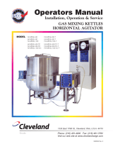
The Groen TA/3 (Figure 1) is an electrically powered, twin shaft scraper mixer, which serves Groen
cooker/mixers with capacities of 40 to 80 gallons. The mixer is mounted with a kettle on a common
support. To permit easy cleaning of the equipment and emptying of the kettle, a hinge in the back
allows the mixer to be tilted out of the kettle.
Model TA/3 has a gearmotor (1 1 -1 /2 or 2 HP at high speed) that drives removable agitators
through a transfer case. The stainless steel agitators consist of a primary agitator, which
continuously scrapes the bottom and side of the kettle, and a faster, counterrotating, secondary
agitator, which operates between the center line and the wall of the kettle.
A control knob turns the three-position selector switch to choose low or high speed operation or to
switch the mixer off. For safety, the mixer also has an automatic tilt cutoff switch, which shuts off
power to the gearmotor when the mixer is swung up out of the kettle.
Installation of the TA/3 requires connection to 208,240, or 480 V, 3 PH electrical service. If the
mixer is employed with an electrically heated kettle, a separate electrical connection is required for
the kettle heating elements.
For a description of the kettle component of your cooker/mixer, see the separate kettle manual.
2

Installation & Start-Up
A. INSTALLATION
Your Groen mixer has been test operated at the factory and furnished with all internal wiring,
complete and ready for final connection. A wiring diagram is furnished on the inside of the
service panel.
WARNING: INSTALLATION OF THE COOKER/MIXER MUST BE DONE BY PERSONNEL QUALIFIED
TO WORK WITH ELECTRICITY. IMPROPER INSTALLATION CAN RESULT IN INJURY TO
PERSONNEL AND/OR DAMAGE TO EQUIPMENT.
WARNING: ANY MECHANICAL OR ELECTRICAL CHANGE MUST BE APPROVED BY THE GROEN
FOOD SERVICE ENGINEERING DEPARTMENT.
1. Installation under a ventilation hood or exhaust fan is recommended.
2. Set the cooker/mixer in place and level it. Confirm that there is enough rear wall and overhead
clearance to tilt the mixer safely through its entire tilting range. Provide enough clearance to permit
access for service. Fasten the unit legs or base to the floor to eliminate any chance that the unit could
tip over.
3. Provide the proper electric power supply as specified on the electrical information plate attached to the
equipment. Observe local codes and/or The National Electrical Code in accordance with ANSI/NFPA
70 - latest edition. The installation should conform to the code that has the more strict requirements.
4. Connect electrical service with waterproof conduit and waterproof connectors.
WARNING: TO PREVENT POSSIBLE ELECTRIC SHOCK, GROUND THE UNIT AT THE TERMINAL
PROVIDED.
5. The following check list may be used to confirm the correctness of the installation.
— Unit level
— Adequate clearance for tilting
— Access for service
— Unit fastened down
— Mixer power supply conforms to information plate and code
— Electrical conduit and connections are waterproof
— Mixer grounded
For instructions on installing the kettle component of your cooker/mixer, see the separate kettle
manual.
B. START-UP
After the mixer is installed, the installer should confirm that the equipment is operating correctly.
1. Make sure the gear case of the gearmotor is filled to the proper level with AGMA #7 oil. The transfer
case under the gearmotor is permanently lubricated and needs no additional lubrication.
2. At the circuit breaker or fuse box, turn on the electric power supply to the mixer.
3. Tilt the mixer to confirm that it can swing back far enough and there is no interference when the kettle is
tilted.
4. Make sure that each agitator is properly seated on its drive shaft and that the drive pin is fully engaged
with the coupling.
3

Figure 2
5. Carefully examine the primary agitator to make sure that every nylon finger is positioned (Fi-
gure 2) so the flat side will be against the kettle wall and the beveled side will face the
center of the kettle. An inverted finger will not sweep the surface of the kettle and may be
damaged or knocked off the agitator.
6. When the mixer is in operating position, the primary agitator should be centered in the kettle,
and all the nylon fingers should touch the inside of the kettle.
7. Confirm that the mixer operates correctly at low and high speeds.
8. Make sure the primary agitator turns in the correct direction, so it pushes the fingers ahead
of the agitator bar.
If the mixer functions as described above, it is ready for use. If it does not, contact your
authorized Groen Service Agency.
For instructions on initial start-up of the kettle component of your cooker/mixer, see the
separate kettle manual.
4

Operation
1. To mount the agitators on the mixer drive, first unfasten the latch by pulling the latch handle.
The spring lift mechanism will start to raise the drive. Tilt the drive as far back as it will go.
2. You can make the agitators easier to install and remove by putting a little mineral oil or other
suitable lubricant on the drive shafts.
3. Mount the larger (primary) agitator on the drive shaft that operates over the center of the kettle
and the smaller (secondary) agitator on the other shaft. Slide the agitator up onto the shaft as
far as it will go, then turn the agitator and pull it down, so the stud on the shaft becomes firmly
seated against the end of the the J-slot (Figure 3).
Figure 3
4. Before you operate the mixer, confirm that each agitator is properly connected with its shaft.
This precaution will prevent damage to the unit.
WARNING: MIXER CAN CAUSE INJURY BY STARTING AUTOMATICALLY, IF POWER IS ON
WHEN THE MIXER IS LOWERED INTO THE KETTLE.
5. Grasp the latch handle and lower the mixer into operating position, tilting the kettle forward
slightly so the agitator will clear the lip of the kettle.
WARNING: STARTING THE MIXER IN HIGH SPEED MAY CAUSE MATERIAL TO SPILL OUT
OF THE KETTLE.
6. To run the mixer, turn the red control knob clockwise to LOW SPEED or counterclockwise to
HIGH SPEED. For some products you should start at low speed and then switch to high speed.
You may switch between low and high speeds without stopping.
7. To stop the mixer, push the control knob.
8. Always switch oft the mixer before you tilt it.
9. To tilt the mixer out of the kettle, first unfasten the latch by pulling the latch handle. As you tilt
the mixer up, tilt the kettle forward slightly so the agitator will clear the wall of the kettle.
10. As you continue to raise the mixer, scrape oft any product that is clinging to the agitators.
Removing product from the agitators will keep it from dripping on the outside of the
cooker/mixer.
WARNING: THE WEIGHT OF PRODUCT LEFT ON THE AGITATORS CAN MAKE THE MIXER
FALL BACK INTO THE KETTLE.
11. When you have tilted the mixer all the way back, it should stay in that position.
12. When the cooker/mixer is to be cleaned or serviced, or when it will not be used for a week or
longer, shut oft all supplies of electric power to the unit.
For instructions on operating the kettle component of your cooker/mixer, see the separate
kettle manual.
5

Cleaning
A. SUGGESTED TOOLS & MATERIALS
1. Cleaner, like HC-10 or HC-32 from ECOLAB, Inc.
2. Stiff brush
3. Sanitizer, like Klenzade XY-12
B. PRECAUTIONS
WARNING: BEFORE CLEANING ANY PART OF THE MIXER, OTHER THAN THE AGITATORS, SHUT
OFF ALL ELECTRIC POWER TO THE COOKER/MIXER AT THE CIRCUIT BREAKER OR
FUSE BOX, TO AVOID POSSIBLE ELECTRIC SHOCK.
WARNING: KEEP WATER AND SOLUTIONS OUT OF THE CONTROLS, ELECTRICAL WIRING, AND
DRIVE MECHANISM. NEVER SPRAY OR HOSE THE MIXER.
C. PROCEDURE
1. Wash the agitators as soon as possible after use. If the unit is in continuous use, thoroughly clean all
parts of the mixer at least once every 12 hours.
2. Take each agitator off its drive shaft by pushing the agitator up toward the drive housing, then turning
the agitator and pulling it down, to slip the J-slot off the stud on the shaft. Remove the nylon fingers
from the primary agitator by removing the hair pin clip and sliding the fingers off the end of the agitator
bar.
WARNING: AVOID CONTACT WITH THE CLEANER, AS RECOMMENDED BY THE SUPPLIER.
CAREFULLY READ THE WARNINGS AND FOLLOW THE DIRECTIONS ON THE LABEL
OF THE CLEANER. MANY CLEANERS ARE HARMFUL TO THE SKIN, EYES, MUCOUS
MEMBRANES, AND CLOTHING.
3. Prepare a hot solution of the cleaning compound as instructed by the supplier. Wash the agitator parts
and rinse them well.
NOTE: To obtain the sweeping action and avoid damage, make sure each nylon finger is replaced on
the agitator with the flat side against the kettle wall and the beveled side toward the center of
the kettle (Figure 1).
Use a cloth moistened with the cleaning solution to clean other parts of the mixer.
4. To remove materials stuck to the agitators, use a brush, sponge, cloth, plastic or rubber scraper, or
plastic wool along with the cleaning solution. To make washing easier, let the cleaning solution soak
into the residue. When you clean the stainless steel parts, do not use any abrasive material (like metal
sponges or scouring powder) or metal implement (like a spoon, scraper, or wire brush) that might
scratch the surface. Scratches make the surface hard to clean and provide places for bacteria to grow.
Do not use steel wool, which may leave particles imbedded in the surface and cause eventual
corrosion and pitting.
5. As part of the daily cleaning program, clean all surfaces that may have been soiled. Remember to
check such parts as the back and underside of the drive housing, back of the control console, etc.
6. When the agitators need to be sanitized, use a sanitizing solution equivalent to one that supplies 100
parts per million available chlorine. Obtain advice on the best sanitizing agent from your supplier of
sanitation products. Following the supplier's directions, apply the sanitizer after the agitators have been
washed, then rinse off the sanitizer completely. It is recommended that the agitators be sanitized just
before use.
CAUTION: NEVER LEAVE A SANITIZER in contact with the surface of stainless steel LONGER
THAN 30 MINUTES. Longer contact can cause corrosion.
7. Outside stainless steel surfaces may be polished with a recognized stainless steel cleaner like "Zepper"
from Zep Manufacturing Company.
Cleaning procedures for the kettle component of your cooker/mixer are described in the separate
kettle manual.
6

OPERATOR'S
Troubleshooting List
The mixer is designed to operate smoothly and efficiently if properly maintained. However, the
following is a list of checks to make in the event of a problem.
If following the directions in this list does not correct the problem, call an authorized Groen Service
Agency.
SYMPTOM WHAT TO CHECK
a. That power is turned on at the circuit breaker
b. or fuse box.
c. That power is being supplied to the building.
d. Fuse in the drive housing.
e. For a mechanical overload, that is, too much
material in the kettle or material that is too
thick or hard to mix.
Motor overheats and/or sparks excessively. a. For an overload.
Fuse blows frequently, a. For an overload.
Troubleshooting guidance for the kettle component of your cooker/mixer is contained in the
separate kettle manual.
Service
WARNING: USE OF ANY REPLACEMENT PARTS OTHER THAN THOSE SUPPLIED BY GROEN OR
THEIR AUTHORIZED DISTRIBUTOR VOIDS ALL WARRANTIES AND CAN CAUSE BODILY
INJURY TO THE OPERATOR AND DAMAGE TO THE EQUIPMENT.
SERVICE PERFORMED BY OTHER THAN FACTORY AUTHORIZED PERSONNEL WILL
VOID ALL WARRANTIES.
A. PERIODIC SERVICE
1. The interior of the drive housing should be kept clean and dry.
2. Electrical wiring should be kept securely connected and in good condition.
3. Regular service of the mixer should include cleaning the motor, checking the motor brushes and
commutator, and lubricating the gears and pivot points.
B. COMPONENT REPLACEMENT
WARNING: BEFORE REPLACING ANY PARTS, SHUT OFF ALL ELECTRIC POWER SUPPLIES TO
THE COOKER/MIXER TO PREVENT ELECTRIC SHOCK.
All internal wiring is marked as shown on the schematic drawings. Be sure that new components are wired
in the same manner as the old components.
C. SERVICE RECORDS
A Service Log is provided with the warranty information. Each time service is performed on this Groen
equipment, enter the date on which the work was done, what was done, and who did it. The owner should
file the log with the warranty.
Service procedures for the kettle component of the cooker/mixer are described in the separate kettle manual.
7
Motor will not run.
Motor runs at low speed only.
Motor speed varies rapidly.
a. For a mechanical overload.
a. For an oscillating load, by disconnecting the
mixer drive from the agitators and checking
motor speed.

Service Troubleshooting
If an item in the "WHAT TO CHECK" column is followed by an asterisk (*), the work should be done
only by an authorized Groen Service Representative. Some items in the "What to Check" list may not
apply to a particular size of cooker/mixer.
SYMPTOM WHAT TO CHECK
a. Power supply to the unit.
b. For a mechanical overload.
c. Fuse in the drive housing.
d. That the tilt switch is closed.*
e. For
a ground or short in the motor.*
f. Overload heaters.*
a. For a mechanical overload.
b. Motor brushes for wear or improper seating.*
c. For open motor field circuit, by checking field current.*
a. For an oscillating load, by disconnecting the mixer drive
from the agitator and checking motor speed.
b. Motor brushes for wear, improper seating, or sticking in
the holders.*
c. Motor for a ground.*
a. For an overload.
b. Motor brushes for wear or improper seating.*
c. Grade of brushes used.*
Motor will not run.
Motor runs slowly.
Motor speed varies rapidly.
Motor overheats and/or
sparks excessively
Fuse blows or heater
cuts out frequently.
a. For an overload.
b. Whether line voltage is too high.*
c. Motor armature and wiring for ground or short.*
d. For open motor field circuit, by checking field current.*
e. For defective circuit breaker.*
Troubleshooting guidance for the kettle component of your cooker/mixer is contained in the separate
kettle manual.
References
KLENZADE SALES CENTER — ECOLAB, INC.
370 Wabasha
St. Paul, Minnesota 55102
800/328-3663 or 612/293-2233
NATIONAL FIRE PROTECTION ASSOCIATION
60 Battery March Park
Quincy, Massachusetts 02269
NATIONAL SANITATION FOUNDATION
3475 Plymouth Rd.
Ann Arbor, Michigan 48106
ZEP MANUFACTURING CO.
1390 Lunt Avenue
Elk Grove Village, Illinois 60007
NFPA/70 The National Electrical Code
8

Parts List
To order parts, contact your authorized Groen Service Agency. Supply the model designation, part description, part number,
quantity, and where applicable, voltage and phase.
WARNING: USE ONLY GROEN SUPPLIED PARTS, SUBSTITUTION OF UNAUTHURIZED PARTS OR GENERIC
PARTS CAN CAUSE BODILY INJURY TO THE OPERATOR AND DAMAGE TO THE EQUIPMENT.
ITEM
NO.
PART
NO.
DESCRIPTION
1 TA/2-58 TRANSFER CASE ASSEM. DWQ. D-5762-SH.7 (20-30 &
40 GAL.)
2 TA/2-58TRASFERCASEASSEM. DWG. D-5762-
SH.9(60S80GAL.)
3 9574 CONTACTOR, FURNAS #41 DA 30AG (3-POLE)
4 4436 INTERLOCK SWITCH
5 7517 MERCURY SWITCH & CLIP
6 6972 21 /2" DIA. COVER PLATE (3-HOLE)
7 6975 21 /2- DIA. RUBBER GASKET (3-HOLE)
8 9212 RBC PITCHLIGN ROLLER BEARING
9 6974 21 /2" DIA. RUBBER GASKET (1 -HOLE)
10 6973 2 1/2 /2'' DIA. COVER PLATE (1 -HOLE)
22 2927 ALUMINUM ADAPTER PLATE, 10-5/8" x 3/4'' *
37 9715 10" LG, DIE SPRING (20 & 30 GAL.)
38 9670 12"LG.DIESPRING(40GAL)
39 9671 7" LG. DIE SPRING (60 GAL. TOP & 40 GAL. BOTTOM)
40 9691 8" LG. DIE SPRING (80 GAL.)
41 9714 6" LG. DIE SPRING (20 & 30 GAL.)
42 9690 5"LG.DIESPRING(60GAL.)
43 9672 BRONZE BUSHING
44 9673 BRONZE BUSHING
45 9237 SPRING
46 17005
SPRING PLUNGER, ROD & ROLLER ASSY.
47 9236 BRONZE BUSHING
48 9122 RUBBERSNUBBER
OVERLOADS:
AGITATORS:
* Adapter Plate required with item 53 only.
For the kettle parts list, see the separate kettle
manual.
9
KETTLE SIZE PRIMARY SECONDARY
40 GAL
60 GAL
80 GAL
9243
9244
9245
9686
9687
9688
ITEM
NO.
PART
NO.
DESCRIPTION
51
GEARMOTOR (SEE MOTOR TABLE)
61 6502 FINGER SCRAPER
62 12947 HAIR PIN CLIP
63 2943 RELAYTHERMAL
64 16296 TRANSFORMER
65 55572 FUSE 1AMP
66 2121
SPONGE RUBBER GASKET, VERTICAL STRIP,
5/32 x 1 /2 x 10-1 /8''
67 5233 SPONGE RUBBER GASKET, 5/32 x 1 /2 x 8"
68 — OVERLOAD HEATER (SEE TABLE)
69 — AGITATOR (SEE TABLE)
40 GAL 60 & 80 GAL.
VOLTAGE HIGH LOW HIGH LOW
208
240
480
41845
48517
61268
45359
50854
6948
15518
61269
48516
41845
15927
26713

Part List (40 gallon models)
To order parts, contact your authorized Groen Service Agency. Supply the model designation, part description, part
number, quantity, and where applicable, voltage and phase.
WARNING: USE ONLY GROEN SUPPLIED PARTS, SUBSTITUTION OF UNAUTHURIZED PARTS OR GENERIC PARTS
CAN CAUSE BODILY INJURY TO THE OPERATOR AND DAMAGE TO THE EQUIPMENT.
40 GAL. ASSY
ITEM
PART
NO. NO. DESCRIPTION
7 9268 PINION-24TOOTH-3.000P.DIA.
19 9269 GEAR-64TOOTH-8.000P.DIA.
NOTE: 40 GAL. ASSY. (COMPLETE) - #9927
10
ITEM
NO.
PART
NO.
NO.
REQD.
DESCRIPTION
1
1 SEE MOTOR TABLE
2 3557 1 EXTENDED SHAFT
3 9262 1 KEY, 1/4" SQUARE X1-1/4-LG
4 9263 1 FRONT SECTION HOUSING, ALUMINUM
5 9305 1 COUPLING PIN, 1/2x1-3/4'
6 12012
1 SET COLLAR, 1" ID
7
1 CELERON PINION (SEE TABLE)
8 9223 2
SNAP RING, EXTERNAL, ZINC PLATED, FOR 1"
SHAFT
9 9209 3 BEARING, CYLINDRICAL BRONZE,
1'IDx1-1/20Dx1-1,'2'LG
10 9204 1 ECCENTRIC BRG. HOUSING, ALUMINUM
11 5656
16 LOCKWASHER5/16"
12 5613
16 SCREW, HEX HEAD CAP, 5/16"-18 x 1 • LG
13 12100
3 GREASE FITTING, STRAIGHT, 1/8'NPT
14 1758 2 SEAL, SHAFT, 1/4x1" ID x1-5/8" OD
15 9203 1 FRONT BEARING HOUSING, ALUMINUM CASTING
16 9557 1 PRIMARY SHAFT, 1x11-1/2”
17 9258 1 KEY, 1/4" SQUARE x 2" LG
18 9208 1 THRUST WASHER, 5/16" x 1' ID x 2-7/8" OD
19
1 GEAR (SEE TABLE)
20
1 PUSH BUTTON
21 9205 TOP BEARING HOUSING,
POLISHED ALUMINUM CASTING
22 6009 4 SCREW, ROUNDHEAD, # 10-24 x 3/8" LG
23 9259 1 SWITCH PLATE, ALUMINUM, 2-3/4'' SQUARE
24
1 SWITCH MOUNTING NUT
25 64086
1 INDICATOR PLATE FOR 3 - POSITION SWITCH
26
4 WASHER
27 54798
1 SELECTOR SWITCH, 3 - POSITION
28 9253 1 COUPLING PIN, 3/8x7/8"
29
1 GASKET

Parts Lists (60/80 gallon models)
To order parts, contact your authorized Groen Service Agency. Supply the model designation, part description, part number, quantity, and
where applicable, voltage and phase.
WARNING: USE ONLY GROEN SUPPLIED PARTS, SUBSTITUTION OF UNAUTHURIZED PARTS OR GENERIC PARTS CAN
CAUSE BODILY INJURY TO THE OPERATOR AND DAMAGE TO THE EQUIPMENT.
PART
NO.
2924
2925
2926
2921
2922
2933
DESCRIPTION
2 - SPEED GEARMOTOR -1 -1 2 to 3/4 HP, 200V, 3 PH, 60 HZ (40gal)
2 - SPEED GEARMOTOR -1-1 210 3,4 HP, 230V, 3 PH, 60 HZ (40gal)
2 - SPEED GEARMOTOR • 1 -1 2 to 3/4 HP - 460V, 3 PH, 60 HZ, (40 gal)
2 - SPEED GEARMOTOR, 2 to 1 HP, 200V, 3 HP, 60 HZ (60 & 80 gal)
2 - SPEED GEARMOTOR, 2 to 1 HP,230V ,3PH ,60 HZ (60 & 80 gal)
2 – SPEED GEARMOTOR ,2 to 1 HP ,460V ,3PH ,60 HZ (60 & 80 gal)
ITEM
NO.
PART
NO.
NO.
REQD.
DESCRIPTION
1 1 SEE MOTOR TABLE
2 2927
1 ALUMINUM ADAPTER PLATE, 10-5/8 x 3/4"
3 3558
1 EXTENDED SHAFT
4 9249
1 KEY, 1/4" SQUARE x 1-1/2" LONG
5 9250
1 FRONT SECTION HOUSING, ALUMINUM
6 9253
1 COUPLING PIN, 3/8 x7'8"
7 12012
1 SET COLLAR, 1" ID
8 1 CELERON PINION (SEE TABLE)
9 9223
2 SNAP RING, EXTERNAL, ZINC PLATED, FOR 1" SHAFT
10 9209
3 BEARING, CYLINDRICAL BRONZE,
1" ID x 1-1/2" OD x 1-1/ 2" LONG
11
60 GAL. ASSY
ITEM
PART
NO. NO. DESCRIPTION
8
20
9254
9260
PINION - 28 TOOTH - 3.500 P. DIA.
GEAR-72TOOTH-9.000P.DIA.
80 GAL. ASSY
ITEM
PART
NO. NO. DESCRIPTION
8
20
9255
9261
PINION-32TOOTH-4.000PDIA.
GEAR-80TOOTH-10.000P.DIA.
ITEM
NO.
PART
NO.
NO.
REQD.
DESCRIPTION
11 9204 1 ECCENTRIC BRG. HOUSING, ALUMINUM
12 5656 12 LOCKWASHER5/16"
13 5613 12 SCREW, HEX HEAD CAP, 5/16"-18x1"LG
14 12100
3 GREASE FITTING, STRAIGHT, 1/8" NPT
15 1758 2 SEAL, SHAFT, 1 /4" x 1" ID x 1 -5/8" OD
16 9203 1
FRONT BEARING HOUSING, ALUMINUM
CASTING
17 9557 1 PRIMARY SHAFT, 1x11-1/2"
18 9258 1 KEY, 1/4" SQUARE x 2" LONG
19 9208 1 THRUSTWASHER,5/16"x1"IDx2-7/8"OD
20
1 GEAR (SEE TABLE)
21
1 PUSHBUTTON
22 9205 1 TOP BEARING HOUSING,
POLISHED ALUMINUM CASTING
23 6009 4 SCREW, ROUND HEAD, #10-24x 3/8" LG.
24 9259 1 SWITCH PLATE, ALUMINUM, 2-3/4" SQUARE
25
1 SWITCH MOUNTING NUT
26 64086
1 INDICATOR PLATE FOR 3 - POSITION SWITCH
27
4 WASHER
28 54798
1 SELECTOR SWITCH, 3 - POSITION
29 5610 8 SCREW, HEX HEAD CAP, 1 /4"-20 x 1" LG.
30 5655 8 LOCKWASHER 1/4"
31 9305 1 PIN, COUPLING, 1/2x1-3/4"
32 5623 4 SCREW, HEX HEAD CAP, 1/2"-13xl-1/4"LG.
33 5657 4 LOCKWASHER 12"
34
1 GASKET


LIMITED WARRANTY TO
COMMERCIAL PURCHASERS
(Continental U.S., Hawaii & Canadian Sales Only)
I. Groen Foodservice Equipment ("Groen Equipment") has been skillfully manufactured, carefully inspected
and packaged to meet rigid standards of excellence. Groen warrants its Equipment to be free from
defects in material and workmanship for (12) twelve months, with the following conditions and subject to
the following limitations.
II. This parts and labor warranty is limited to Groen Equipment sold to the original commercial
purchaser/users (but not original equipment manufacturers), at its original place of installation, in the
continental United States, Hawaii and Canada.
III. Damage during shipment is to be reported to the carrier, is not covered under this warranty, and is the
sole responsibility of purchaser/user.
IV. Groen, or an authorized service representative, will repair or replace, at Groen's sole election, any Groen
Equipment, including but not limited to, draw-off valves, safety valves, gas and electric components,
found to be defective during the warranty period. As to warranty service in the territory described above,
Groen will absorb labor and portal to portal transportation costs (time & mileage) for the first twelve (12)
months from date of installation or fifteen (15) months from date of shipment from Groen.
V. This warranty does not cover boiler maintenance, calibration, periodic adjustments as specified in
operating instructions or manuals, and consumable parts such as scraper blades, gaskets, packing, etc.,
or labor costs incurred for removal of adjacent equipment or objects to gain access to Groen Equipment.
This warranty does not cover defects caused by improper installation, abuse, careless operation, or
improper maintenance of equipment. This warranty does not cover damage caused by poor water quality
or improper boiler maintenance.
VI. THIS WARRANTY IS EXCLUSIVE AND IS IN LIEU OF ALL OTHER WARRANTIES, EXPRESSED OR
IMPLIED, INCLUDING ANY IMPLIED WARRANTY OF MERCHANTABILITY OR FITNESS FOR A
PARTICULAR PURPOSE. EACH OF WHICH IS HEREBY EXPRESSLY DISCLAIMED. THE
REMEDIES DESCRIBED ABOVE ARE EXCLUSIVE AND IN NO EVENT SHALL GROEN BE LIABLE
FOR SPECIAL, CONSEQUENTIAL OR INCIDENTAL DAMAGES FOR THE BREACH OR DELAY IN
PERFORMANCE OF THIS WARRANTY.
Groen Equipment is for commercial use only. If sold as a component of another (O.E.M.) manufacturer's
equipment, or if used as a consumer product, such Equipment is sold AS IS and without any warranty.
* (Covers All Foodservice Equipment Ordered after October 1, 1995)
OM
-
TA/3
(3/90)
1900
Pratt Boulevard
Elk Grove Village, Illinois ,60007
Telephone: (708) 439-2400
/