Page is loading ...

1333 East 179th St., Cleveland, Ohio, U.S.A. 44110
Phone: (216) 481-4900 Fax: (216) 481-3782
Visit our web site at www.clevelandrange.com
Operators Manual
Installation, Operation & Service
GAS MIXING KETTLES
HORIZONTAL AGITATOR
Cleveland
™
MODEL: HA-MKGL-60 HA-MKGL-60-T
HA-MKGL-80 HA-MKGL-80-T
HA-MKGL-100 HA-MKGL-100-T
HA-MKGL-60-CC HA-MKGL-60-CC-T
HA-MKGL-80-CC HA-MKGL-80-CC-T
HA-MKGL-100-CC HA-MKGL-100-CC-T
SE95022 Rev. 6
Enodis

FOR THE USER
WARNING: Improper installation,
adjustment, alteration, service or
maintenance can cause property
damage, injury or death. Read the
installation and operating
instructions thoroughly before
installing or servicing this
equipment.
FOR YOUR SAFETY
DO NOT STORE OR USE GASOLINE
OR ANY OTHER
FLAMMABLE LIQUIDS AND
VAPOURS IN THE VICINITY
OF THIS OR ANY OTHER
APPLIANCE.
IMPORTANT!
ENSURE KETTLE IS AT ROOM TEMPERATURE AND
PRESSURE GAUGE IS SHOWING ZERO OR LESS PRESSURE
PRIOR TO REMOVING ANY FITTINGS.
.
IMPORTANT
The following points are to insure the safe installation and operation of this equipment:
• Insure all gas and electrical supplies match rating plate and electrical stickers.
• Observe all clearance requirements.
• Disconnect the electrical power supply to the appliance before cleaning or servicing unit.
• All service must be performed by a qualified Cleveland Range Technician.
• Do not obstruct the flow of combustion and ventilation air.
The installation and connection must comply with current local codes, or in the absence of local codes, with
CAN/CGA-B149.1 and .2 installation code or with the national fuel gas code, ANSI Z223.1-L988.
Post in a prominent location, instructions to be followed in the event the user smells gas. This information shall
be obtained by consulting your local gas supplier.
The appliance and its individual shut off valve must be disconnected from the gas supply piping system during
any pressure testing of that system at test pressures in excess of 1/2 psig. (3.45 kpa).
The appliance must be isolated from the gas supply piping system by closing its individual manual shut off
valve during any pressure testing of the gas supply piping system at test pressures equal to or less than 1/2
psig. (3.45 kpa).
RETAIN THIS MANUAL FOR YOUR REFERENCE.

Shut off power at main
fuse disconnect prior
to servicing.
Ensure kettle is at room
temperature and pressure
gauge is showing zero or less
prior to removing any fittings.
Inspect unit daily for
proper operation.
0
Do not fill kettle above
recommended level
marked on outside of kettle.
Surfaces may be
extremely hot! Use
protective equipment.
Keep appliance and area free
and clear of combustibles.
Stand clear of product
discharge path when
discharging hot product.
Wear protective equipment
when discharging hot product.
Do not lean on or place
objects on kettle lip.
Do not attempt to operate
this appliance during a
power failure.
Keep clear of pressure
relief discharge.
Keep hands away from
moving parts and pinch points.
SERVICING
IMPORTANT
CAUTION
DANGER
GAS APPLIANCES
For your safety

GENERAL
Installation of the kettle must be accomplished by
qualified installation personnel working to all applicable
local and national codes. Improper installation of
product could cause injury or damage.
This equipment is built to comply with applicable standards
for manufacturers. Included among those approval agencies
are: UL, A.G.A., NSF, ASME/N.Bd., CSA, CGA, ETL, and
others. Many local codes exist, and it is the responsibility of
the owner/installer to comply with these codes.
Observe all clearance requirements to provide proper make-
up air flow as well as sufficient clearance for servicing.
Dimensions and clearance specifications are shown on the
specification sheet and in the Clearance Requirements
section. Do not install kick plates or otherwise obstruct the
flow of combustion and ventilation air.
Check rating plate to ensure that kettle has been equipped
to operate with the type of gas available at the installation.
VENTILATION
Gas fired kettles are only to be installed under a
ventilation hood in a room which has provisions for
adequate make up air. Further information can be
obtained by referring to the U.S.A. National Fire
Protection Associations NFPA96 regulations. These
standards have also been adopted by the National
Building Code in Canada.
INSPECTION
Before unpacking visually inspect the unit for evidence
of damage during shipping. If damage is noticed, do
not unpack the unit, follow shipping damage
instructions.
SHIPPING DAMAGE
INSTRUCTIONS
If shipping damage to the unit is discovered or
suspected, observe the following guidelines in
preparing a shipping damage claim.
1. Write down a description of the damage or the
reason for suspecting damage as soon as it is
discovered. This will help in filling out the claim
forms later.
2. As soon as damage is discovered or suspected,
notify the carrier that delivered the shipment.
3. Arrange for the carrier's representative to examine
the damage.
4. Fill out all carrier claims forms and have the
examining carrier sign and date each form.
CLEARANCE REQUIREMENTS
This unit must be installed in accordance with the
clearances shown on the rating label which is adhered
to the unit.
FOR YOUR SAFETY. Keep the appliance area free and
clear of combustible materials.
KETTLE
1. When removing the kettle from the platform, handle
with care to prevent scratching or any other
damage. It is imperative that the kettle be level
before bolting to the floor. This will prevent any
twist or out of roundness to the kettle and will stop
deflection of the agitator. Make sure the kettle is
securely bolted to the floor and follow the
procedure listed below:
⇒ Raise the flange on the leg under the motor so
that it sets freely (stationary kettles only).
⇒ Position the kettle in its permanent location,
check clearances and level the kettle by turning
the adjustable feet.
⇒ Lower the flange or flanges under the motor
channel. Over adjustment, whether up or down,
could cause misalignment and cause damage to
the agitator drive shaft and hub (stationary kettles
only).
2. Next you must check the alignment of the drive
shaft for a uniform clearance between the hub and
the shaft. In order to check for clearance you must
remove the seal cover plate and pull the seal back.
You can check the distance for clearance by using
a wire feeler gauge.
3. If adjustment is required for side direction, loosen
the motor bolts, center the shaft and retighten.
If vertical alignment is needed, loosen the motor
bolts and add a shim to raise or remove a shim to
lower. Retighten bolts. When this is complete,
check to see if the agitator shaft coupling slides
freely for easy removal of the agitator.
4. Once positioned and leveled, permanently secure
the kettle’s flanged feet to the floor using 1/2 x 2 I/2
inch lag bolts and floor anchors (supplied by the
installer). Two bolts per leg are required to secure
each of the flanged feet.
CONTROL PANEL
Refer to Wiring Diagram supplied with Control Panel for
installation instructions.
INSTALLATION

GAS
It is recommended that a sediment trap (drip leg) be
installed in the gas supply line. If the gas pressure
exceeds 14” water column, a pressure regulator must
be installed, to provide a maximum of 14” water column
gas pressure to the gas control valve.
Connect the gas supply piping to the input side of the
gas control valve. Location and pressure data are
shown on the specification sheet.
Installation must be in accordance with local codes
and/or the National Fuel Gas Code ANSI Z223.1-1988
(USA) or the Installation Codes for Gas Burning
Appliances and Equipment CANI B149.1 and B149.2
(Canada). Use a gas pipe joint compound which is
resistant to L.P. gas. Test all pipe joints for leaks with
soap and water solution. Ensure that the gas pressure
regulator is set for the manifold pressure indicated on
the gas rating plate.
The appliance and its individual shut-off valve must be
disconnected from the gas supply piping system during
any pressure testing of that system at test pressures in
excess of 1/2 psi (3.45 kPa). The appliance must be
isolated from the gas supply piping system by closing
its individual manual shut-off valve during any pressure
testing of the gas supply piping system at test
pressures equal to or less than 1/2 psi (3.45 kPa).
ELECTRICAL
Electrical installation must be in accordance with local
codes and/or the National Electric Code ANSI/NFPA 70-
1990 (USA) or the Canadian Electrical Code CSA
Standard C22.1 (Canada). The kettle must be
electrically grounded by the installer.
A separate fused disconnect switch must be supplied
and installed in the high voltage electrical supply line.
The wire gauge size and electric supply must match the
power requirements specified on the kettle’s rating
plate. The waterproof conduit enclosed permanent
copper wiring must be adequate to carry the required
current at the rated voltage. Refer to the
SPECIFICATION SHEET or RATING LABEL for electrical
specifications and location of electrical connections.
Remove the screws securing the component cover
(located to the left rear side of kettle), and remove the
cover. A wiring diagram is affixed to the inside of the
cover. Feed conduit enclosed permanent copper wiring
through the cut-out in the bottom of the console and
fasten to the terminal block. Fasten the ground wire to
the ground lugs connected to the frame, beside the
terminal block. Replace the console cover and secure it
with the screws.
WATER
The sealed jacket of the gas-fired kettle is precharged
with the correct amount of a water-based formula, and
therefore, no water connection is required to the kettle
jacket.
CLEANING
After installation the kettle must be thoroughly cleaned
and sanitized prior to cooking.
WARRANTY
Our Company supports a worldwide network of
Maintenance and Repair Centres. Contact your nearest
Maintenance and Repair Centre for replacement parts,
service, or information regarding the proper
maintenance and repair of your cooking equipment
In order to preserve the various agency safety
certification (UL, A.G.A., NSF, ASME/Ntl. Bd., etc.), only
factory-supplied replacement parts should be used. The
use of other than factory supplied replacement parts will
void warranty.

OPERATING INSTRUCTIONS
Temperature Sensor
Senses temperature of product
Automatic Dump Valve
Empties kettle of either food product or wash water
Sight Glass
For checking water level of kettle jacket
Vacuum /Pressure Gauge
Indicates steam pressure inside steam jacket in PSI, as
well as vacuum in inches of mercury
Gas Shut-Off Valve
Air Quick Connect
Push yellow tab down to release air pressure before
disconnecting air hose
Kettle Filler Nozzle
A
Red Low Water Indicator Light
When lit, in the upright position, indicates kettle gas
burner has cut out and unit requires more water.
Occasional pulsing of this light is normal.
Green Heat Indicator Light
When lit, indicates gas burner is on; cycles on-off with
solid state controls.
Solid State Temperature Control Knob /
On-Off Toggle Switch
Controls electrical power to kettle. and allows operator to
select kettle heat increments from minimum, 1-10.
A setting of 7 or higher will boil water
Amber Ignition Failure Indicator Light
Indicates failure of heating system to ignite
(Used prior to July 2004)
B
Agitator Stop Button
Stops agitator in case of emergency
Agitator Start Switch
Starts agitator. Agitator power control switch must be ON
Agitator Power Switch
Allows power to agitator. When not in use, turn control
power OFF
Agitator Speed Control Switch
Turn clockwise until desired speed is reached
1
2
3
4
5
6
7
21 3
5
7
6
B
C
D
A
E
4
CCC
Power tilt control switch
Tilts kettle for pouring; some kettles have manual hand tilt
Reset circuit breaker
Protects power tilt system from overload. Push to reset
EEE
DDD
Fill Interrupt Switch
Interrupts water fill cycle
Potable Fill Water Switch
Selects hot or cold water
Fill Cycle Switch
Start/continue cycle switch
Product Discharge Valve Switch
Toggle momentary switch to desired valve opening
Water Meter Digital Counter (not shown)
Location may vary dependant on customer's specific
options
0 123
NOTE:
Location of
switches may
vary dependant
on customers
specific options
Parts Description -
Kettle

General
WARNING: Do not attempt to operate this appliance
during a power failure. Keep appliance and area free and
clear of combustibles.
Before turning kettle on, ensure that following
conditions exist:
• If you are cooking an egg or milk product, do not
pre-heat kettle.
• The vacuum/pressure gauge needle is in green
zone; if it is not and is in "vent air" zone, call your
service agent to repair leak.
• The electrical service to kettle is turned on
NOTE: The kettle should be sanitized prior to the daily
production run - see CLEANING INSTRUCTIONS .
Mixing ("AGITATOR ")
WARNING:
•
Never add product to kettle while agitator is running.
•
Do not put hands in kettle.
•
Watch for loose clothing near agitator.
1. Turn "SPEED CONTROL" to "0".
2. Switch agitator to "ON".
3. Push agitator "START" to initiate mixing.
4. Turn "SPEED CONTROL" to desired mixing speed.
5. To stop mixing action, push agitator stop button.
NOTE: Mixing speed depends on the product
consistency. The faster the mixing speed the more
damage may be done to fragile product.
Heating (General Notes)
• The green light cycles on and off, indicating that
burners are cycling to maintain set temperature.
• The red "low water" light should not be lit during
operation. This light indicates that water level is
critically low and that gas burners have
automatically shut off. Before further use, refer to
RESERVOIR FILL INSTRUCTIONS for adding
distilled water.
• Occasional flashing of the red "low water" light is ok
while kettle is heating.
Manual Heating
1. Switch "POWER" to "ON".
2. Turn temperature control knob to desired setting.
3. Switch "CONTROLLER" to "BYPASS".
4. After closing discharge valve, place product in kettle.
Automatic Heating
1. Switch "CONTROLLER" to "ACTIVE".
2. Turn temperature control knob to "10".
3. Continually push function key " " until "OFF" is
displayed.
4. Push and hold key " " or " " until desired
temperature is set.
5. To Start:
push function key
" " until "CtrL" is displayed.
6. Push down key " ".
7. To Stop:
push function key
" " until "OFF" is displayed.
8. Push down key " ".
9. After closing discharge valve, place product in kettle.
Emptying the Kettle
1. To open automatic dump valve:
• Turn PRODUCT DISCHARGE VALVE switch
clockwise to JOG TO OPEN. Release switch to the
HOLD position when desired valve opening is
achieved.
• To close valve, turn switch counterclockwise to
CLOSED position.
2. To avoid splashing, slowly empty kettle contents into
an appropriate container by partially opening dump
valve.
NOTE: When pumping with a Metering Filling Station the
speed of the agitator arm must be sufficient to suspend
the heavier items in the mix in order to achieve an even
distribution in your packaged items.
3.
Immediately clean kettle as outlined in CLEANING
INSTRUCTIONS on page.
Water Meter
1. Switch "POTABLE FILL WATER" to "HOT" or "COLD".
2. Set required volume by first pushing the " " key
until the digit you want to change is flashing in the
lower display. Then use the " " key to change the
value of the selected digit.
When all digits are set, press the "ENT" key.
3. Locate delivery spout over kettle.
4. Turn switch to "RESET". Delivery will start at "0" and
stop at preset volume.
5. To stop delivery at any time, turn "FILL INTERRUPT"
switch to " ● ".
6. To complete delivery after interrupting, turn switch
"FILL CYCLE" to "CONTINUE".

CARE AND CLEANING
Cooking equipment must be cleaned regularly to
maintain its fast, efficient cooking performance and
to ensure its continued safe, reliable operation. The
best time to clean is shortly after each use (allow
unit to cool to a safe temperature).
WARNINGS
➩ Do not use detergents or
cleansers that are chloride
based or contain quaternary
salt.
➩ Do not use a metal bristle
brush or scraper.
➩ Steel wool should never be
used for cleaning the stainless
steel.
➩ Unit should never be cleaned
with a high pressure spray
hose.
➩
Do not leave water sitting in unit
when not in use.
Stagnant
Water
High Pressure
Spray Hose
Chloride Cleaners
Steel Pads
Wire Brush &
CLEANING INSTRUCTIONS
CAUTION
SURFACES MAY
BE EXTREMELY HOT!
CLEANING INSTRUCTIONS
1. Turn unit off.
2. Remove drain screen (if applicable). Thoroughly
wash and rinse the screen either in a sink or a
dishwasher.
3. Prepare a warm water and mild detergent solution in
the unit.
4. Remove food soil using a nylon brush.
5. Loosen food which is stuck by allowing it to soak at
a low temperature setting.
6. Drain unit.
7. Rinse interior thoroughly.
8. If the unit is equipped with a
T
T
a
a
n
n
g
g
e
e
n
n
t
t
D
D
r
r
a
a
w
w
-
-
O
O
f
f
f
f
V
V
a
a
l
l
v
v
e
e
, clean
as follows:
a) Disassemble the draw-off valve first by turning
the valve knob counter-clockwise, then turning
the large hex nut counter-clockwise until the
valve stem is free of the valve body.
b) In a sink, wash and rinse the inside of the valve
body using a nylon brush.
c)
Use a nylon brush to clean tangent draw-off tube.
d) Rinse with fresh water.
e) Reassemble the draw-off valve by reversing the
procedure for disassembly. The valve's hex nut
should be hand tight only.
9. If the unit is equipped with a
B
B
u
u
t
t
t
t
e
e
r
r
f
f
l
l
y
y
V
V
a
a
l
l
v
v
e
e
, clean
a
s follows:
a) Place valve in open position.
b) Wash using a warm water and mild detergent
solution.
c) Remove food deposits using a nylon brush.
d) Rinse with fresh water.
e) Leave valve open when unit is not in use.
10. Using mild soapy water and a damp sponge, wash
the exterior, rinse, and dry.
NOTES
➩ For more difficult cleaning applications one of the
following can be used: alcohol, baking soda, vinegar,
or a solution of ammonia in water.
➩ Leave the cover off when the kettle is not in use.
➩ For more detailed instructions refer to the Nafem
Stainless Steel Equipment Care and Cleaning manual
(supplied with unit).

FLUSH PISTON VALVE
(Used prior to 2003.)
Daily - clean valve as follows:
To remove valve from kettle:
1. Place valve in open position.
2. Holding bottom of valve, loosen and remove sani-
clamp (1).
3. Lower valve, and remove from body.
4. Remove sani-clamp seal (2) and "O" ring (3).
5. With valve on its side, turn air dial
counterclockwise to extend plunger.
6. Disconnect air supply at valve.
7. Being careful not to submerge entire valve in water,
wash cylinder body (4), inside valve body (5), "O"
ring and seal.
⇒ Wash in a sink, using a warm water and mild
detergent solution.
⇒ Rinse with fresh water and then sanitize using a
properly diluted sanitizing solution.
⇒ Allow to air dry thoroughly on a flat, clean
surface.
To install valve on kettle:
1. Replace "O" ring and seal if worn.
2. Coat cylinder body and "O" ring with cooking oil or
food safe grease.
3.
Coat kettle cylinder with cooking oil.
4.
Reconnect air supply.
5.
With valve on its side, place valve in open position
by turning air regulator clockwise.
6.
Put valve in place, and secure with sani-clamp.
(Used after 2003.)
Daily - clean valve as follows:
1.
Open product valve.
2.
Disconnect air hoses.
3.
Remove air cylinder.
4.
Remove valve tee.
5.
Remove all O-rings.
6.
Clean air cylinder, do not submerge in water. Wipe
clean and sanitize.
7.
Clean and sanitize tee and O-rings.
8.
Grease and reinstall O-rings.
9.
Reinstall tee to kettle outlet.
10.
Reinstall air cylinder to bottom of tee.
11.
Reconnect air hoses.
12.
Close valve and check for alignment.
5
2
3
4
1
Air regulator
Controls air flow to
automatic dump valve,
turn clockwise to open and
counterclockwise to close
(extend plunger)
Air quick connect
Push yellow tab down to
release air pressure before
disconnecting air hose
4
AIR VALVE
ASSEMBLY
FPVA-3
AIR HOSE
AIR
CYLINDER
AIR HOSE
OPEN
POSITION
CLOSED
POSTITION
0-RING
CLAMP
0-RING
VALVE
TEE
0-RING
CLAMP
KETTLE
OUTLET
KETTLE

AGITATOR
To remove and clean agitator (two-person
job):
1. Remove scraper blades.
2. Rotate agitator until pull pin is on top side.
3. Turn power OFF.
4. Pull pin out.
5. Slide coupling toward kettle wall, and carefully lift
agitator pulling back to lift out.
6. Clean in a sink, using a warm water and mild
detergent solution.
7. Rinse with fresh water.
Agitator shaft
Pin
Coupling
SCRAPER BLADES
To remove and clean scraper blades:
Fig. 2 Fig. 3Fig. 1
Scraper
blade
Back stop
Pin A
Pin B
Tool
Spring
To Install Scraper Blade
1. Slide scraper blade and spring onto Pin A as shown in Fig. 1.
2. Hook spring arm and pull up.
3. Using tool, engage spring arm into groove on Pin B.
Scraper blade is now in place.
To Remove Scraper Blade
1. Insert tool that is provided as shown in Fig. 2.
2. Pull up on spring arm until arm clears groove in Pin B.
3. Spring is now disengaged, gently release spring to remove
scraper blade.
AGITATOR BUSHING
With agitator out, remove bushing by:
1. Remove bushing by turning 1/4 turn and pulling
away from the kettle wall.
2. Clean, rinse and sanitize bushing and bushing
mounting area.
3. Lubricate metal surfaces with food safe grease.
4. Install bushing by locating retaining pin and sliding
bushing on.
5. Rotate to lock into position.
Slot
Bushing
Retaining
pin
Agitator
Shaft
1. Remove scraper blades using the tool to release the
spring from the retaining pin and sliding the blade off
the shaft.
2. Place parts in a pan of warm water to soak.
3. Clean in a sink, using a warm water and mild
detergent solution.
4. Rinse with fresh water.
5. Allow to dry thoroughly on a flat, clean surface.

QUAD RING
(Used prior to June 1999)
To clean agitator quad ring:
1. Remove retaining knobs.
2. Slide shaft seal retainer plate and quad ring away
from kettle body.
3. Clean quad ring, shaft, and seal retainer plate with
clean cloth.
4. Rinse with fresh water.
5. Apply light coat of food safe grease to both sides
of the quad ring.
6. Slide quad ring back into original position, making
sure it does not twist.
7. Slide retainer plate back toward kettle, replacing
retaining knobs.
8. Tighten with hand pressure only.
SEAL RETAINER PLATE
(Replaces QUAD RING after June 1999.)
To clean seal retainer plate:
1. Apply food safe grease to grease nipples untill you
see clean grease inside the kettle. Grease daily.
Quad ring
Seal retainer plate
Retaining knobs
Seal
retaining
plate
“O”
ring
Seal
Grease Nipples
Wave
washer
Silicone
filled
seal
Retainer
Bolt &
washer
Seal
retaining
plate
“O”
ring
Seal
Wave
washer
Silicone
filled
seal
Retainer
Bolt &
washer
Retaining ring
Hole cap
Retaining bolt
Retaining
washer
Retaining ring seat
A

STAINLESS STEEL EQUIPMENT CARE AND CLEANING
(suppled courtesy of Nafem. For more information visit their web site at www.nafem.org)
Contrary to popular belief, stainless steels ARE susceptible to rusting.
Corrosion on metals is everywhere. It is recognized quickly on iron and
steel as unsightly yellow/orange rust. Such metals are called “active”
because they actively corrode in a natural environment when their atoms
combine with oxygen to form rust.
Stainless steels are passive metals because they contain other metals, like
chromium, nickel and manganese that stabilize the atoms. 400 series
stainless steels are called ferritic, contain chromium, and are magnetic;
300 series stainless steels are called austenitic, contain chromium and
nickel; and 200 series stainless, also austenitic, contains manganese,
nitrogen and carbon. Austenitic types of stainless are not magnetic, and
generally provide greater resistance to corrosion than ferritic types.
With 12-30 percent chromium, an invisible passive film covers the steel’s
surface acting as a shield against corrosion. As long as the film is intact
and not broken or contaminated, the metal is passive and stain-less. If the
passive film of stainless steel has been broken, equipment starts to
corrode. At its end, it rusts.
Enemies of Stainless Steel
There are three basic things which can break down stainless steel’s
passivity layer and allow corrosion to occur.
1. Mechanical abrasion
2. Deposits and water
3. Chlorides
Mechanical abrasion means those things that will scratch a steel surface.
Steel pads, wire brushes and scrapers are prime examples.
Water comes out of the faucet in varying degrees of hardness. Depending
on what part of the country you live in, you may have hard or soft water.
Hard water may leave spots, and when heated leave deposits behind that
if left to sit, will break down the passive layer and rust stainless steel. Other
deposits from food preparation and service must be properly removed.
Chlorides are found nearly everywhere. They are in water, food and table
salt. One of the worst chloride perpetrators can come from household and
industrial cleaners.
So what does all this mean? Don’t Despair!
Here are a few steps that can help prevent stainless steel rust.
1. Use the proper tools.
When cleaning stainless steel products, use non-abrasive tools. Soft
cloths and plastic scouring pads will not harm steel’s passive layer.
Stainless steel pads also can be used but the scrubbing motion must
be in the direction of the manufacturers’ polishing marks.
2. Clean with the polish lines.
Some stainless steel comes with visible polishing lines or “grain.”
When visible lines are present, always scrub in a motion parallel to the
lines. When the grain cannot be seen, play it safe and use a soft cloth
or plastic scouring pad.
3. Use alkaline, alkaline chlorinated or non-chloride containing cleaners.
While many traditional cleaners are loaded with chlorides, the industry
is providing an ever-increasing choice of non-chloride cleaners. If you
are not sure of chloride content in the cleaner used, contact your cleaner
supplier. If your present cleaner contains chlorides, ask your supplier if
they have an alternative. Avoid cleaners containing quaternary salts; it
also can attack stainless steel and cause pitting and rusting.
4. Treat your water.
Though this is not always practical, softening hard water can do much
to reduce deposits. There are certain filters that can be installed to
remove distasteful and corrosive elements. To insure proper water
treatment, call a treatment specialist.
5. Keep your food equipment clean.
Use alkaline, alkaline chlorinated or non-chloride cleaners at
recommended strength. Clean frequently to avoid build-up of hard,
stubborn stains. If you boil water in stainless steel equipment,
remember the single most likely cause of damage is chlorides in the
water. Heating cleaners that contain chlorides have a similar effect.
6. Rinse, rinse, rinse.
If chlorinated cleaners are used, rinse and wipe equipment and
supplies dry immediately. The sooner you wipe off standing water,
especially when it contains cleaning agents, the better. After wiping
equipment down, allow it to air dry; oxygen helps maintain the
stainless steel’s passivity film.
7. Never use hydrochloric acid (muriatic acid) on stainless steel.
8. Regularly restore/passivate stainless steel.
Recommended cleaners for specific situations
Job Cleaning Agent Comments
Routine cleaning Soap, ammonia, Apply with cloth or sponge
detergent, Medallion
Fingerprints & smears Arcal 20, Lac-O-Nu Provides barrier film
Ecoshine
Stubborn stains & Cameo, Talc, Zud, Rub in direction of polish lines
discoloration First Impression
Grease & fatty acids, Easy-off, De-Grease Excellent removal on all finishes
blood, burnt-on-foods It Oven Aid
Grease & oil Any good Apply with sponge or cloth
commercial detergent
Restoration/Passivation Benefit, Super Sheen
Review
1. Stainless steels rust when passivity (film-shield) breaks down as a
result of scrapes, scratches, deposits and chlorides.
2. Stainless steel rust starts with pits and cracks.
3. Use the proper tools. Do not use steel pads, wire brushes or scrapers
to clean stainless steel.
4. Use non-chlorinated cleaners at recommended concentrations. Use
only chloride- free cleaners.
5. Soften your water. Use filters and softeners whenever possible.
6. Wipe off cleaning agent(s) and standing water as soon as possible.
Prolonged contact causes eventual problems.
To learn more about chloride-stress corrosion and how to prevent it,
contact the equipment manufacturer or cleaning materials supplier.
Developed by Packer Engineering, Naperville, Ill., an independent testing
laboratory.

10
HA MIXERS
SERVICE PARTS
WARRANTY
O
ur Company supports a worldwide network of Maintenance and Repair Centers. Contact your nearest Maintenance and Repair Centre for replacement parts, serv-
ice, or information regarding the proper maintenance and repair of your cooking equipment.
In order to preserve the various agency safety certification (UL, NSF, ASME/Ntl. Bd., etc.), only factory-supplied replacement parts should be used. The use of other
than factory supplied replacement parts will void warranty.
FAUCET ASSEMBLY
ITEM # PART # DESCRIPTION QTY.
SPK11 SINGLE PANTRY FAUCET for Tilting Kettles (includes items 1-10)
DPK11 DOUBLE PANTRY FAUCET for Tilting Kettles (includes items 1-8 & 11)
SPK5 SINGLE PANTRY FAUCET for Stationary Kettles
(includes items 1-10)
DPK5 DOUBLE PANTRY FAUCET for Stationary Kettles (includes items 1-8 & 11)
1. KE50825-11 3/4" SPOUT for - SPK11 & DPK11 . . . . . . . . . . . . . . . . . . . . . . . . . . . . . . . . . . . . . . . . . . .1
KE50825-5 3/4" SPOUT for - SPK5 & DPK5 . . . . . . . . . . . . . . . . . . . . . . . . . . . . . . . . . . . . . . . . . . . . .1
2. FA95007-10 RETAINING RING . . . . . . . . . . . . . . . . . . . . . . . . . . . . . . . . . . . . . . . . . . . . . . . . . . . . . . . .1
3. FA05002-19 "O" RING . . . . . . . . . . . . . . . . . . . . . . . . . . . . . . . . . . . . . . . . . . . . . . . . . . . . . . . . . . . . . . .1
4. KE51736 LONG FAUCET NUT . . . . . . . . . . . . . . . . . . . . . . . . . . . . . . . . . . . . . . . . . . . . . . . . . . . . . .1
5. KE54159 FAUCET MOUNTING BRACKET for Tilting Kettles
. . . . . . . . . . . . . . . . . . . . . . . . . . . . . . .1
6. FA11258 HEX CAP SCREW . . . . . . . . . . . . . . . . . . . . . . . . . . . . . . . . . . . . . . . . . . . . . . . . . . . . . . . .2
7. FA31029 LOCK WASHER . . . . . . . . . . . . . . . . . . . . . . . . . . . . . . . . . . . . . . . . . . . . . . . . . . . . . . . . . .2
8. FA210028 HEX NUT . . . . . . . . . . . . . . . . . . . . . . . . . . . . . . . . . . . . . . . . . . . . . . . . . . . . . . . . . . . . . . .2
9. KE51401 SINGLE PANTRY BODY (c/w item 13) . . . . . . . . . . . . . . . . . . . . . . . . . . . . . . . . . . . . . . . .1
10. KE50335 ADAPTER WASHER . . . . . . . . . . . . . . . . . . . . . . . . . . . . . . . . . . . . . . . . . . . . . . . . . . . . . .1
11. KE51403 DOUBLE PANTRY BODY (c/w item 13 & 14) . . . . . . . . . . . . . . . . . . . . . . . . . . . . . . . . . . .1
12. SE50447 REPLACEMENT HORSESHOE WASHER . . . . . . . . . . . . . . . . . . . . . . . . . . . . . . . . . . . . . .1
13. SE50021 REPLACEMENT STEM ASSEMBLY, COLD WATER . . . . . . . . . . . . . . . . . . . . . . . . . . . . . .1
14. SE50020 REPLACEMENT STEM ASSEMBLY, HOT WATER . . . . . . . . . . . . . . . . . . . . . . . . . . . . . . . .1
1
9
11
10
13
1314
12
6
5
7
8
6
5
7
8
2
3
4

Agitator
Shaft
1 2 3
4 5 76
Prior to October 2003
After October 2003
15 14 8 9 10 11 12 13
SCRAPER BLADES
ITEM NO. PART NO. DESCRIPTION QTY.
1. KE54602 SCRAPER BLADE . . . . . . . . . . . . . . . . . 7
2. KE54608 SPRING . . . . . . . . . . . . . . . . . . . . . . . . . 7
3. KE01976 SPRING REMOVAL TOOL . . . . . . . . . . 1
COMPLETE AGITATOR ASSEMBLY
(NOT KE02286-1 60 GALLON . . . . . . . . . . . . . . . . . . . . . . 1
SHOWN)
KE02286-2 80 GALLON . . . . . . . . . . . . . . . . . . . . . 1
KE02286-3 100 GALLON . . . . . . . . . . . . . . . . . . . . 1
1
2
3
AGITATOR SEAL ASSEMBLY
ITEM PART
NO. NO. DESCRIPTION QTY.
1. KE01911 RETAINING KNOBS . . . . . . . . . . 3
2. KE54592 SEAL RETAINER PLATE . . . . . . . 1
3. FA05002-8 "O" RING . . . . . . . . . . . . . . . . . . . 1
4. KE54594 PIN . . . . . . . . . . . . . . . . . . . . . . . 1
5. KE54583 COUPLING . . . . . . . . . . . . . . . . . 1
6. KE54593 IDLER PIN . . . . . . . . . . . . . . . . . . 1
7. KE54590 BUSHING . . . . . . . . . . . . . . . . . . 1
8. KE54592 SEAL RETAINER PLATE . . . . . . . 1
9. FA05002-48 "O" RING . . . . . . . . . . . . . . . . . . . 1
10. KE55458 SEAL . . . . . . . . . . . . . . . . . . . . . . 1
11. KE55457 SST WAVE WASHER . . . . . . . . . . 1
12. KE55456 SILICONE FILLED SEAL . . . . . . . 1
13. KE55455 RETAINER FOR LIP SEALS . . . . . 1
14. FA11509-5 BOLT, HEX HEAD, 3/8 16 x 2 1/2 2
15. FA31031 WASHER, 3/8 18-8 . . . . . . . . . . . 2
16. KE600583 GREASE NIPPLE, 1/8 NPT . . . . . 2
OPERATING CONTROLS
ITEM NO. PART NO. DESCRIPTION QTY.
1. KE54531 BUTTON, AGITATOR STOP . . . . . . . . . . . . . .1
2. KE54530 BUTTON, AGITATOR START . . . . . . . . . . . . .1
KE603106 LED LAMP . . . . . . . . . . . . . . . . . . . . . . . . . . .1
3. KE54529 SWITCH, AGITATOR POWER . . . . . . . . . . . . .1
4. KE54532 SWITCH, SPEED CONTROL . . . . . . . . . . . . .1
2
1
3
4
SERVICE PARTS

PRESSURE RELIEF ASSEMBLY
5
4 3 1
2
ITEM NO. PART NO. DESCRIPTION QTY.
1. FA05049 MALE CONNECTOR, 1/2" PIPE - 1/4" TUBE . . . . . . . . . . . . . . . . . . . . . . . . . . . .1
2. FI00151 STREET ELBOW, 1/2" . . . . . . . . . . . . . . . . . . . . . . . . . . . . . . . . . . . . . . . . . . . . .2
3. FI00178 TEE, 1/2" FPT, BRASS . . . . . . . . . . . . . . . . . . . . . . . . . . . . . . . . . . . . . . . . . . . . .1
4. KE54941-5 SAFETY VALVE, 50 PSI, 1/2" (NORTH AMERICA) . . . . . . . . . . . . . . . . . . . . . . .1
KE54941-31 SAFETY VALVE, 50 PSI, 1/2", (EUROPE) . . . . . . . . . . . . . . . . . . . . . . . . . . . . . .1
5. KE54223 BLOW DOWN TUBE . . . . . . . . . . . . . . . . . . . . . . . . . . . . . . . . . . . . . . . . . . . . . .1
SIGHT GLASS
ITEM ON. PART NO. DESCRIPTION QTY.
1. KE50955 RETAINING COVER . . . . . . . . 1
2. KE52871 WASHER . . . . . . . . . . . . . . . . 1
3. KE51053-1 SIGHT GLASS . . . . . . . . . . . . 1
4. FA05002-30 ”O” RING . . . . . . . . . . . . . . . . 1
1
LO
HI
2
3
4

HINGE ASSEMBLY
1
5
32
1312
6
4
7
11
8
10
9
9
ITEM NO. PART NO. DESCRIPTION QTY.
Hinge Assembly
1. - 11 KE00597-1 25 - 40 Gallon, 20 Gallon Full Jacketed . . . . . . . . . . . . . . . . . . . . . . . . . . . . . . .1
KE00597-2 60 - 80 Gallon, 30 - 40 Gallon Full Jacketed . . . . . . . . . . . . . . . . . . . . . . . . . . .1
KE00597-3 100 - 150 Gallon, 60 - 100 Gallon Full Jacketed . . . . . . . . . . . . . . . . . . . . . . . .1
KE00597-4 KDM-60, KDM-60-T, Cook Tank . . . . . . . . . . . . . . . . . . . . . . . . . . . . . . . . . . . . .1
KE00597-5 KDL-200, KDL-250, KDL-150-F, KDL-250-F . . . . . . . . . . . . . . . . . . . . . . . . . . . .1
1. KE50822 Hinge Base . . . . . . . . . . . . . . . . . . . . . . . . . . . . . . . . . . . . . . . . . . . . . . . . . . . . .1
2. KE51217 Hinge Cylinder . . . . . . . . . . . . . . . . . . . . . . . . . . . . . . . . . . . . . . . . . . . . . . . . . .1
3. KE50121-2 Hinge Spring Light - for KE00597-2 . . . . . . . . . . . . . . . . . . . . . . . . . . . . . . . . .1
KE50121-1 Hinge Spring Heavy - for KE00597-1, KE00597-3, KE00597-4, KE00597-5, . .1
4. KE50823-1 Hinge Pin . . . . . . . . . . . . . . . . . . . . . . . . . . . . . . . . . . . . . . . . . . . . . . . . . . . . . . .1
5. KE50824 Hinge Bearing . . . . . . . . . . . . . . . . . . . . . . . . . . . . . . . . . . . . . . . . . . . . . . . . . . .1
6. KE50819-1 Hinge End Piece . . . . . . . . . . . . . . . . . . . . . . . . . . . . . . . . . . . . . . . . . . . . . . . . .1
7. KE50820 Hinge Insert . . . . . . . . . . . . . . . . . . . . . . . . . . . . . . . . . . . . . . . . . . . . . . . . . . . . .1
8. KE50819 Hinge End Piece . . . . . . . . . . . . . . . . . . . . . . . . . . . . . . . . . . . . . . . . . . . . . . . . .1
9. FA11284 Screw, Socket Head . . . . . . . . . . . . . . . . . . . . . . . . . . . . . . . . . . . . . . . . . . . . . .4
10. FA11507 Cutting Screw, . . . . . . . . . . . . . . . . . . . . . . . . . . . . . . . . . . . . . . . . . . . . . . . . . .2
11. SK50418 Plug Button . . . . . . . . . . . . . . . . . . . . . . . . . . . . . . . . . . . . . . . . . . . . . . . . . . . . .1
12. KE50151-2 Knob . . . . . . . . . . . . . . . . . . . . . . . . . . . . . . . . . . . . . . . . . . . . . . . . . . . . . . . . . .1
13. Cover Handle (specify model) . . . . . . . . . . . . . . . . . . . . . . . . . . . . . . . . . . . . . .1

FLUSH PISTON VALVE (USED PRIOR TO 2003)
ITEM NO. PART NO. DESCRIPTION QTY.
T40430 Valve Assembly (includes parts 1 - 16) . . . . . . . . . . . . . . . . . . . . . . . . .1
1. FA05000 "O" Ring, Cylinder Head . . . . . . . . . . . . . . . . . . . . . . . . . . . . . . . . . . . . .1
2. KE52345 Piston Shaft . . . . . . . . . . . . . . . . . . . . . . . . . . . . . . . . . . . . . . . . . . . . . . .1
3. KE52346 Air seal . . . . . . . . . . . . . . . . . . . . . . . . . . . . . . . . . . . . . . . . . . . . . . . . . .1
4. KE52347 Sani-Clamp Seal, 4” . . . . . . . . . . . . . . . . . . . . . . . . . . . . . . . . . . . . . . .1
5. KE52344 Sani-Clamp, 4” . . . . . . . . . . . . . . . . . . . . . . . . . . . . . . . . . . . . . . . . . . . .1
6. FA05002-22 "O" Ring, Cylinder Body . . . . . . . . . . . . . . . . . . . . . . . . . . . . . . . . . . . . .2
7. FA05002-21 "O" Ring, Piston . . . . . . . . . . . . . . . . . . . . . . . . . . . . . . . . . . . . . . . . . . . .2
8. KE52315 Piston . . . . . . . . . . . . . . . . . . . . . . . . . . . . . . . . . . . . . . . . . . . . . . . . . . .1
9. KE52335 Compression Spring . . . . . . . . . . . . . . . . . . . . . . . . . . . . . . . . . . . . . . . .1
10.-13. SE00040 Supply Hose Assembly, Piston . . . . . . . . . . . . . . . . . . . . . . . . . . . . . . . .1
10. KE52341 Hose Barb, 1/8” x 1/4” . . . . . . . . . . . . . . . . . . . . . . . . . . . . . . . . . . . . . .3
11. KE52340 Supply Hose, 8” . . . . . . . . . . . . . . . . . . . . . . . . . . . . . . . . . . . . . . . . . . .1
12. KE52342 Hose Barb, 1/4” x 1/4” . . . . . . . . . . . . . . . . . . . . . . . . . . . . . . . . . . . . . .1
13. KE52338 Quick Connect Male End . . . . . . . . . . . . . . . . . . . . . . . . . . . . . . . . . . . .1
14. KE52327 Piston Top . . . . . . . . . . . . . . . . . . . . . . . . . . . . . . . . . . . . . . . . . . . . . . . .1
15. KE52328 Piston Cylinder . . . . . . . . . . . . . . . . . . . . . . . . . . . . . . . . . . . . . . . . . . . .1
16. KE52314 Bottom Nut . . . . . . . . . . . . . . . . . . . . . . . . . . . . . . . . . . . . . . . . . . . . . . .1
Rev 2

ITEM NO. PART NO. DESCRIPTION QTY.
1. KE55210 WELD RING, KETTLE BOTTOM OUTLET . . . . . . . . . . . . . . . . . . . . . . . . . . . . . 1
2. FI05144-3 SANI CLAMP, 3” . . . . . . . . . . . . . . . . . . . . . . . . . . . . . . . . . . . . . . . . . . . . . . . . . 2
3. KE52154-4 GASKET, SANI CLAMP, 3” . . . . . . . . . . . . . . . . . . . . . . . . . . . . . . . . . . . . . . . . . 2
4. KE02291 COMPLETE ACTUATOR AND DISCHARGE VALVE ASSEMBLY . . . . . . . . . . . . 1
INCLUDES PARTS 5. - 13.
5. KE55248 BUNA-N O-RING . . . . . . . . . . . . . . . . . . . . . . . . . . . . . . . . . . . . . . . . . . . . . . . . .1
6. KE55249 REPLACEABLE S.S. PLUNGER HEAD . . . . . . . . . . . . . . . . . . . . . . . . . . . . . . . .1
7. KE55250 BUNA-N O-RING . . . . . . . . . . . . . . . . . . . . . . . . . . . . . . . . . . . . . . . . . . . . . . . . .1
8. KE55251 1/8 NPT S.S. HYDRAULIC CLOSE NIPPLE . . . . . . . . . . . . . . . . . . . . . . . . . . . .2
9. KE55252 MALE S.S. QUICK DISCONNECT . . . . . . . . . . . . . . . . . . . . . . . . . . . . . . . . . . . .1
10. KE55253 AIR OPERATED CYLINDER . . . . . . . . . . . . . . . . . . . . . . . . . . . . . . . . . . . . . . . .1
11. KE55254 FEMALE S.S. QUICK DISCONNECT . . . . . . . . . . . . . . . . . . . . . . . . . . . . . . . . .1
12. FA05002-53 BUNA-N O-RING . . . . . . . . . . . . . . . . . . . . . . . . . . . . . . . . . . . . . . . . . . . . . . . . .2
13. KE55256 FEMALE S.S. QUICK DISCONNECT . . . . . . . . . . . . . . . . . . . . . . . . . . . . . . . . .1
1
3
2
12
13
12
5
6
7
8
10
9
8
11
4
AIR VALVE
ASSEMBLY
FPVA-3
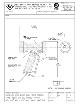
FLUSH PISTON VALVE (USED AFTER 2003)

ITEM NO. PART NO. DESCRIPTION QTY.
1. KE601603 QUICK CONNECT . . . . . . . . . . . . . . . . . . . . . . . . . . . . . . . . . . . . . . . . . . . . . . . .1
2. KE54280 SLIDE VALVE . . . . . . . . . . . . . . . . . . . . . . . . . . . . . . . . . . . . . . . . . . . . . . . . . . . .I
3. FA30512 SPACER WASHER . . . . . . . . . . . . . . . . . . . . . . . . . . . . . . . . . . . . . . . . . . . . . . . .1
4. FA32500 TOOTH LOCK WASHER 7/8" DIA. . . . . . . . . . . . . . . . . . . . . . . . . . . . . . . . . . . .1
5. KE52697 NUT 1/2 NPS BRASS . . . . . . . . . . . . . . . . . . . . . . . . . . . . . . . . . . . . . . . . . . . . . .I
6. KE52931 AIR FITTING . . . . . . . . . . . . . . . . . . . . . . . . . . . . . . . . . . . . . . . . . . . . . . . . . . . .1
7. F100178 TEE 1/2 NPT . . . . . . . . . . . . . . . . . . . . . . . . . . . . . . . . . . . . . . . . . . . . . . . . . . . .1
8. FI00351 BUSHING 1/2 MIP X 1/4 FIP . . . . . . . . . . . . . . . . . . . . . . . . . . . . . . . . . . . . . . . .1
9. FI05318 HOSE BARB 90° ELBOW . . . . . . . . . . . . . . . . . . . . . . . . . . . . . . . . . . . . . . . . . .3
10. FI00151 90° STREET ELBOW 1/2 NPT . . . . . . . . . . . . . . . . . . . . . . . . . . . . . . . . . . . . . . .1
11. FA30090 WASHER 15/16 ID X 1 3/4 OD X 1/8 . . . . . . . . . . . . . . . . . . . . . . . . . . . . . . . . .1
12. 7100595-8 NIPPLE 1/2 NPT X 4 1/2" LONG . . . . . . . . . . . . . . . . . . . . . . . . . . . . . . . . . . . . .1
13. KE55238 FILTER-REGULATOR-LUBRICATOR BLOCK . . . . . . . . . . . . . . . . . . . . . . . . . . .1
14. F105220-1 GEAR CLAMP . . . . . . . . . . . . . . . . . . . . . . . . . . . . . . . . . . . . . . . . . . . . . . . . . . .4
15. FA21006 10-24 S.S. NUT . . . . . . . . . . . . . . . . . . . . . . . . . . . . . . . . . . . . . . . . . . . . . . . . . .2
16. KE532177 PNEUMATIC HOSE 1/4 I.D. X 31" L . . . . . . . . . . . . . . . . . . . . . . . . . . . . . . . . . .1
17. KE532176 PNEUMATIC HOSE 1/4 I.D. X 12 1/2" L . . . . . . . . . . . . . . . . . . . . . . . . . . . . . . .1
18. FA30000 FLAT WASHER #10, ZINC PLATED . . . . . . . . . . . . . . . . . . . . . . . . . . . . . . . . . . .2
19. KE02292 AIR SOLENOID ASSEMBLY (SEE SOLENOID ASSEMBLY DRAWING) . . . . . . .1
20. KE50555-3 GROMMET . . . . . . . . . . . . . . . . . . . . . . . . . . . . . . . . . . . . . . . . . . . . . . . . . . . . .2
21. FA21008 1/4-20 NUT S.S. . . . . . . . . . . . . . . . . . . . . . . . . . . . . . . . . . . . . . . . . . . . . . . . . .2
22. FA30002 FLAT WASHER 1/4 DIA., ZINC PLATED . . . . . . . . . . . . . . . . . . . . . . . . . . . . . . .2
4671211
14 9 13 21 22 9
20
1716
1815
19
RTV ALL AROUND
(NOT SHOWN)
3
1
2
5
8
9
SEE AIR
SOLENOID
ASSEMBLY
PNEUMATICS (USED PRIOR TO 2003)

ITEM NO. PART NO. DESCRIPTION QTY.
1 KE02296 PNEUMATIC ASSEMBLY . . . . . . . . . . . . . . . . . . . . . . . . . . . . . . . . . . . . . . . . . . .1
2 KE02299 PNEUMATIC BOX WELDMENT . . . . . . . . . . . . . . . . . . . . . . . . . . . . . . . . . . . . . .1
3 F105166 QUICK CONNECTOR, 3/8 . . . . . . . . . . . . . . . . . . . . . . . . . . . . . . . . . . . . . . . . .1
4 KE54846-8 GASKET, U-CHANNEL . . . . . . . . . . . . . . . . . . . . . . . . . . . . . . . . . . . . . . . . . . . .1
5 FA95074 NYLON ANCHOR NUT, #8 THREADED HOLE . . . . . . . . . . . . . . . . . . . . . . . . . .6
6 KE55241 COVER, PNEUMATIC BOX . . . . . . . . . . . . . . . . . . . . . . . . . . . . . . . . . . . . . . . . .1
7 KE55242 SEALING WASHER, #8 . . . . . . . . . . . . . . . . . . . . . . . . . . . . . . . . . . . . . . . . . . . .6
8 FA11091 S.S. SCREW, #8-32 X 3/8, BINDING HD . . . . . . . . . . . . . . . . . . . . . . . . . . . . . . .6
9 KE55243 MOUNTING BRACKET, PNEUMATIC BOX . . . . . . . . . . . . . . . . . . . . . . . . . . . . .1
10 FA11255 S.S. HEX HEAD SCREW, I/4-20 X 3/8 . . . . . . . . . . . . . . . . . . . . . . . . . . . . . . . . .3
11 FA30034 1/4 FLAT WASHER . . . . . . . . . . . . . . . . . . . . . . . . . . . . . . . . . . . . . . . . . . . . . . .3
12 FA21008 S.S. NUT, 1/4-20 . . . . . . . . . . . . . . . . . . . . . . . . . . . . . . . . . . . . . . . . . . . . . . . . .3
13 FA11134 S.S. SCREW #10-24 X 3/8, PAN HEAD . . . . . . . . . . . . . . . . . . . . . . . . . . . . . . . .4
14 FA21006 S.S. NUT, #10-24 . . . . . . . . . . . . . . . . . . . . . . . . . . . . . . . . . . . . . . . . . . . . . . . . .4
15 FA30000 WASHER, #10 . . . . . . . . . . . . . . . . . . . . . . . . . . . . . . . . . . . . . . . . . . . . . . . . . . .4
16 KE54280 SLIDE VALVE . . . . . . . . . . . . . . . . . . . . . . . . . . . . . . . . . . . . . . . . . . . . . . . . . . . .1
17 FA30512 SPACER WASHER . . . . . . . . . . . . . . . . . . . . . . . . . . . . . . . . . . . . . . . . . . . . . . . .1
18 KE52931 AIR FITTING. . . . . . . . . . . . . . . . . . . . . . . . . . . . . . . . . . . . . . . . . . . . . . . . . . . . .1
19 KE600814-1 TEE 1/2 NPT, BRASS, FIP X FIP X FIP . . . . . . . . . . . . . . . . . . . . . . . . . . . . . . . .1
20 FI05047 BUSHING, REDUCER, 1/2 NPT X 1/4 NPT . . . . . . . . . . . . . . . . . . . . . . . . . . . . .1
21 KE52697 NUT,1/2 NPT BRASS . . . . . . . . . . . . . . . . . . . . . . . . . . . . . . . . . . . . . . . . . . . . . .1
22 FA32500 LOCKWASHER, INTERNAL TOOTH, 7/8 . . . . . . . . . . . . . . . . . . . . . . . . . . . . . .1
23 F100595-16 NIPPLE,1/2 NPT BRASS . . . . . . . . . . . . . . . . . . . . . . . . . . . . . . . . . . . . . . . . . . .1
24 KE50555-3 GROMMET . . . . . . . . . . . . . . . . . . . . . . . . . . . . . . . . . . . . . . . . . . . . . . . . . . . . .2
25. KE02292 AIR SOLENOID ASSEMBLY (SEE SOLENOID ASSEMBLY DRAWING) . . . . . .1
26. KE55238 FILTER - REGULATOR - LUBRICATOR BLOCK . . . . . . . . . . . . . . . . . . . . . . . . .1
27. KE55239 MOUNTING PLATE, PNEUMATIC ASSEMBLY . . . . . . . . . . . . . . . . . . . . . . . . . .1
28. FI05317-2 HOSE BARB, MALE, 1/4 NPT X 1/4 HOSE . . . . . . . . . . . . . . . . . . . . . . . . . . . . .1
29. FI05167 HOSE BARB, 90° ELBOW . . . . . . . . . . . . . . . . . . . . . . . . . . . . . . . . . . . . . . . . . .1
30. FI05220-1 GEAR CLAMP, 1/4 HOSE . . . . . . . . . . . . . . . . . . . . . . . . . . . . . . . . . . . . . . . . . .1
31. KE53217-6 PNEUMATIC HOSE, 1/4 I.D. X ~12 LONG . . . . . . . . . . . . . . . . . . . . . . . . . . . . .1
25 26
262930
28
SEE AIR
SOLENOID
ASSEMBLY
PNEUMATICS (USED AFTER 2003)
/