Cleveland Range TMKDL-100-T User manual

Type
User manual
INSTALLATION, OPERATION AND SERVICE MANUAL
DIRECT STEAM
MIXER KETTLES
CLEVELAND RANGE INC.
1333 East 179th St.
Cleveland, Ohio
U.S.A. 44110
Toll Free 1-800-338-2204
MODELS: MKDL- 40-T
MKDL- 60-T
MKDL- 80-T
MKDL-100-T
MKDL-125-T
MKDL-150-T
TMKDL- 40-T
TMKDL- 60-T
TMKDL- 80-T
TMKDL-100-T
TMKDL-125-T
TMKDL-150-T
SE95018 Rev. 1
TABLE OF CONTENTS
Installation General . . . . . . . . . . . . . . . . . . . . . . . . . . . . . . . . . . . . . . . . . . . . 1
Inspection. . . . . . . . . . . . . . . . . . . . . . . . . . . . . . . . . . . . . . . . . . . 1
Shipping Damage Instructions . . . . . . . . . . . . . . . . . . . . . . . . . . . 1
Clearance Requirements. . . . . . . . . . . . . . . . . . . . . . . . . . . . . . . . 1
Recommended Floor Drain Location . . . . . . . . . . . . . . . . . . . . . . 1
Moving Unit . . . . . . . . . . . . . . . . . . . . . . . . . . . . . . . . . . . . . . . . . 2
Leveling . . . . . . . . . . . . . . . . . . . . . . . . . . . . . . . . . . . . . . . . . . 2-3
Electrical Service Connections . . . . . . . . . . . . . . . . . . . . . . . . . . . 3
Compressed Air Connection . . . . . . . . . . . . . . . . . . . . . . . . . . . . . 3
Piping Connections. . . . . . . . . . . . . . . . . . . . . . . . . . . . . . . . . . . . 3
Piping Schematic . . . . . . . . . . . . . . . . . . . . . . . . . . . . . . . . . . . . . 4
Steam Requirements for Kettles. . . . . . . . . . . . . . . . . . . . . . . . . . . 4
Steam Pipe Sizing . . . . . . . . . . . . . . . . . . . . . . . . . . . . . . . . . . . . . 4
Quality Assurance Checklist . . . . . . . . . . . . . . . . . . . . . . . . . . . 5-6
Operating Instructions Operating Controls & Indicators Drawing . . . . . . . . . . . . . . . . . . 7
Operating Suggestions . . . . . . . . . . . . . . . . . . . . . . . . . . . . . . . . . 8
Safety . . . . . . . . . . . . . . . . . . . . . . . . . . . . . . . . . . . . . . . . . . . . . . 8
General Operation . . . . . . . . . . . . . . . . . . . . . . . . . . . . . . . . . . . . 8
Lifting & Lowering Bridge . . . . . . . . . . . . . . . . . . . . . . . . . . . . . . 8
Mixing . . . . . . . . . . . . . . . . . . . . . . . . . . . . . . . . . . . . . . . . . . . . . 8
Tilting Kettle. . . . . . . . . . . . . . . . . . . . . . . . . . . . . . . . . . . . . . . . . 8
Discharge Valve . . . . . . . . . . . . . . . . . . . . . . . . . . . . . . . . . . . . . . 9
Adding Water . . . . . . . . . . . . . . . . . . . . . . . . . . . . . . . . . . . . . . . . 9
Water Meter . . . . . . . . . . . . . . . . . . . . . . . . . . . . . . . . . . . . . . . . . 9
Manual Heating/Cooling . . . . . . . . . . . . . . . . . . . . . . . . . . . . . . . 9
Automatic Heating/Cooling . . . . . . . . . . . . . . . . . . . . . . . . . . . . . 9
Mixer Kettle Operation using Cal 9900 . . . . . . . . . . . . . . . . . . . 10
Changing Functions & Operations . . . . . . . . . . . . . . . . . . . . . . . 10
Cleaning Instructions Preproduction Sanitizing Procedure . . . . . . . . . . . . . . . . . . . . . . 11
Sanitizing Solution Chart . . . . . . . . . . . . . . . . . . . . . . . . . . . . . . 11
General. . . . . . . . . . . . . . . . . . . . . . . . . . . . . . . . . . . . . . . . . . . . 11
Automatic Dump Valve . . . . . . . . . . . . . . . . . . . . . . . . . . . . . . . . 12
Butterfly Valve . . . . . . . . . . . . . . . . . . . . . . . . . . . . . . . . . . . . . . 12
Scraper Blades . . . . . . . . . . . . . . . . . . . . . . . . . . . . . . . . . . . . . . 12
Sanitizing . . . . . . . . . . . . . . . . . . . . . . . . . . . . . . . . . . . . . . . . . . 12
Service Parts Warranty. . . . . . . . . . . . . . . . . . . . . . . . . . . . . . . . . . . . . . . . . . . 13
Lubricator . . . . . . . . . . . . . . . . . . . . . . . . . . . . . . . . . . . . . . . . . 13
Filter . . . . . . . . . . . . . . . . . . . . . . . . . . . . . . . . . . . . . . . . . . . . . 13
Remote Control Assembly . . . . . . . . . . . . . . . . . . . . . . . . . . . . . . 14
Main Console Controls. . . . . . . . . . . . . . . . . . . . . . . . . . . . . . . . 15
Switch Configuration . . . . . . . . . . . . . . . . . . . . . . . . . . . . . . . . . 16
Hydraulic Components . . . . . . . . . . . . . . . . . . . . . . . . . . . . . 17-18
Plumbing Assembly - 10" Console . . . . . . . . . . . . . . . . . . . . . . . 19
Plumbing Assembly - 18" Console . . . . . . . . . . . . . . . . . . . . . . . 20
Air System - 10" Console . . . . . . . . . . . . . . . . . . . . . . . . . . . . . . 21
Manual Tilt - 10" Console. . . . . . . . . . . . . . . . . . . . . . . . . . . . . . 22
Power Tilt - 10" Console . . . . . . . . . . . . . . . . . . . . . . . . . . . . 23-24
Water Meter Assembly - 18" Console. . . . . . . . . . . . . . . . . . . 25-26
Electrical Component Assembly . . . . . . . . . . . . . . . . . . . . . . . . . 27
Flush Piston Valve . . . . . . . . . . . . . . . . . . . . . . . . . . . . . . . . . . . 28
Butterfly Valve . . . . . . . . . . . . . . . . . . . . . . . . . . . . . . . . . . . . . . 29
Main Component Reference Chart . . . . . . . . . . . . . . . . . . . . . . . 30
Maintenance Inspection and Maintenance Check List . . . . . . . . . . . . . . . . . . . 31
Airline Lubricator Oil Filling Procedure. . . . . . . . . . . . . . . . . . . 32
Air Filter Replacement Procedure. . . . . . . . . . . . . . . . . . . . . . . . 32
Automatic Dump Valve . . . . . . . . . . . . . . . . . . . . . . . . . . . . . . . . 32
Steam Trap . . . . . . . . . . . . . . . . . . . . . . . . . . . . . . . . . . . . . . . . . 32
Re-Installing Speed Control Cable . . . . . . . . . . . . . . . . . . . . . . . 33
Hydraulic Oil Replacement Procedure . . . . . . . . . . . . . . . . . . . . 33
Lubrication. . . . . . . . . . . . . . . . . . . . . . . . . . . . . . . . . . . . . . . . . 34
Disassembly of Switch Assembly. . . . . . . . . . . . . . . . . . . . . . . . . 34
Solenoid Valve Maintenance . . . . . . . . . . . . . . . . . . . . . . . . . 35-36
Wiring Diagram . . . . . . . . . . . . . . . . . . . . . . . . . . . . . . . . . . . . . 37
Flow Path for Hydraulic System. . . . . . . . . . . . . . . . . . . . . . . . . 38
Spare Parts List . . . . . . . . . . . . . . . . . . . . . . . . . . . . . . . . . . . . . 39
1
GENERAL
Installation of the kettle must be accomplished by
qualified installation personnel working to all applicable
local and national codes. Improper installation of
product could cause injury or damage.
This unit is built to comply with applicable standards for
manufacturers. Included among those approval
agencies are: UL, NSF, ASME/Ntl.Bd., CSA, ETL, CE,
and others. Many local codes exist, and it is the
responsibility of the owner/installer to comply with these
codes.
INSPECTION
Before uncrating, visually inspect the unit for evidence
of damage during shipping. If damage is noticed, do
not unpack the unit, follow shipping damage
instructions.
SHIPPING DAMAGE
INSTRUCTIONS
If shipping damage to the unit is discovered or
suspected, observe the following guidelines in
preparing a shipping damage claim.
1. Write down a description of the damage or the
reason for suspecting damage as soon as it is
discovered. This will help in filling out the claim
forms later. If possible, take a polaroid picture.
2. As soon as damage is discovered or
suspected, notify the carrier that delivered the
shipment.
3. Arrange for the carrier's representative to
examine the damage.
4. Fill out all carrier claims forms and have the
examining carrier sign and date each form.
CLEARANCE REQUIREMENTS
18” is recommended for service access on the
rear of kettle, 0” on the left side and 4" on the
right. If adjoining equipment is over 36" high allow
4" clearance on right side.
RECOMMENDED FLOOR
DRAIN LOCATION
Recommended Floor Drain Location
INSTALLATION
12"
6"
B
A
C
WALL
18" CLEARANCE REQUIRED FOR SERVICE
DRAW-OFF
VALVE
12"
A B C
(T) MKDL-40-T 22 1/8" 51" 31"
(T) MKDL-60-T 22 1/8" 53" 31"
(T) MKDL-80-T 22 1/8" 58" 31"
(T) MKDL-100-T 21 3/4" 61" 31"
(T) MKDL-125-T 21 3/4" 65" 31"
(T) MKDL-150-T 21 3/4" 68" 31"
2
MOVING UNIT
1. While still on skid, move unit as close to final
installation position as possible.
2. Prepare unit for lifting as shown in diagram.
3. Lift gently with a forklift or jacks and remove
skid.
4. Lower gently to ground and remove forklift
and blocking.
5. If unit has to be re-positioned, slide gently. Do
not twist or push one side of unit excessively
and cause binding on trunnions.
Shim as
required
to make
level with
center
console
(front
and back)
4"x4" or larger
(front and back)
Forklift tongsSkid
Flanged feet
Jack
LEVELING
Recommended Leveling Procedure
1. With straight-edge, line the backs of the
consoles up with each other (dotted line A)
.
2.
Level and straight-edge backs of consoles
(dotted
line B)
. Adjustments are made by turning flanges
on back feet only.
3.
Level consoles individually from front to back
(dotted lines C). Adjustments are made by turning
flanges on front feet only.
4. Re-check that the back is level (dotted line B)
and then the front (dotted line D). Adjust if
necessary.
5. Check that mixer bridge is level and
guide pins lock smoothly without
binding. If not repeat steps 1 through 4.
Guide Pins
NOTE: See Operating Instructions before
operating unit.
6. Make electrical connections (see electrical
service connections) and test mixer bridge as
follows:
A/ Raise mixer bridge.
B/ Swing bridge out over centre console.
C/ Swing bridge to the left as far as possible.
B
A
C
D
B
A
C
D
C
C
C
C
Recommended Installation Procedure
Note: Instructions reflect a more complicated twin mixer kettle - process for single mixer kettles is the same.
3
D/ Lower bridge.
E/ Bridge pins should enter pin hole on kettle
perfectly, If not return to step 1 and repeat
leveling steps.
F/ Raise bridge and swing to far right (for twin
mixers only).
G/ Repeat steps D and E (for twin mixers
only).
7. Once positioned and leveled, permanently
secure the kettle's flanged feet to the floor
using 5/16 inch stainless steel lag bolts and
floor anchors (supplied by the installer).
Secure each of the flanged feet with one bolt
in each hole.
8. Connect piping as described in the "PIPING
CONNECTION" section.
ELECTRICAL SERVICE
CONNECTIONS
Install in accordance with local codes and/or the
National Electric Code ANSI/NFPA No 70-1981 (USA)
or the Canadian Electric Code CSA Standard C22.1
(Canada). A separate fused disconnect switch must
be supplied and installed. The kettle must be
electrically grounded by the installer.
The electric supply must match the power
requirements specified on the kettle's rating plate.
The copper wiring must be adequate to carry the
required current at the rated voltage. Refer to the
specification sheet for electrical specifications.
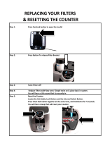
1. Ensure main power is turned off before
connecting wires.
2. Remove the screws at the rear of the center
console cover, and remove the cover. A wiring
diagram is affixed to the underside of the
console cover.
3. Feed permanent copper wiring 18" through the
cut-out in the bottom of the console. Connect
wiring in junction box in the bottom of the
console.
4. Turn main power back on.
5. Check for correct rotation of electric motor
(access by removing top front cover on center
console). If rotation is incorrect, disconnect
main power and reverse any two of the three
live lines.
6. Replace the console cover and secure it with
screws.
COMPRESSED AIR CONNECTION
Mixer Kettles with an air activated discharge valve
require a minimum of 90 PSI to operate correctly.
If the unit is also supplying air to a Metering Filling
Station then a pressure of 100 PSI at a minimum volume
of 25 CFM is required.
The air supplied to the mixer should be clean and dry.
No oil should be added to the supply air. We
recommend the compressed air system be equipped
with a drier, filter, and automatic water dump on the air
compressor receiver tank. If the distance between the
tank and the unit is less than 100 feet then a minimum
line size of 3/4" is required. A distance of 100 to 300 feet
requires a minimum 1" line.
PIPING CONNECTIONS
1. All plumbing to and from the kettle should be
thoroughly cleaned and inspected for dirt and
debris before the final connections to the kettle
are made.
2. Connect all piping according to identification
tags on unit.
3. Piping between boiler and kettle should be
sloped and a drip condensate trap installed at
lowest point.
4. Insulating steam piping is recommended for
safety and higher efficiency.
5. To determine the correct steam supply pipe
size:
A/ Find the total steam requirement using the
first chart.
B/
Use the steam requirement total in the second
chart to find the correct pipe size.
4
STEAM REQUIREMENTS FOR KETTLES
Kettle Cap. Kettle 25psi Steam 265°F 40psi Steam 287°F 80psi Steam 302°F
U.S. Gal. Dia. Lbs./Hr. Hp./Hr. Lbs./Hr. Hp./Hr. Lbs./Hr. Hp./Hr.
40 26" 100 3 120 4 150 4.5
60 29.5" 150 4.5 190 5.5 230 7.0
80 33" 210 6.0 260 7.5 300 9.0
100 36" 260 7.5 320 9.5 390 11.0
125 40" 320 9.5 400 11.5 470 14.0
150 40" 390 11.0 480 14.0 570 17.0
p
Steam requirements are maximum per hour.
p
If more than one unit is on the same line then add the steam usage for each one to reach a total.
STEAM PIPE SIZING
Required pipe length in feet/meters
Steam Required 200 Ft. 400 Ft. 600 Ft.
Lbs./Kg. per hour 60 Meters 125 Meters 185 Meters
100/45 Kg. 3/4" 1" 1 1/4"
200/91 Kg. 1" 1 1/4" 1 1/2"
300/136 Kg. 1" 1 1/4" 1 1/2"
400/182 Kg. 1" 1 1/2" 1 3/4"
500/227 Kg. 1 1/4" 1 1/2" 1 3/4"
700/318 Kg. 1 1/2" 1 3/4" 2"
900/409 Kg. 1 1/2" 1 3/4" 2"
PIPING SCHEMATIC
NOTES:
p Pipe size in inches.
p Less than 50 PSI (3.4
BAR) pressure, increase
pipe size by 1/4".
p 80 to 100 PSI (5.5 to 6.8
BAR), Decrease pipe
size by 1/4".
HOT WATER
COLD WATER
CONDENSATE OUT
COOLING WATER IN
COOLING WATER OUT
STEAM IN
GLOBE VALVES
UNIONS
STRAINERS
DUMP VALVE TO DRAIN
5
The following will be performed before the unit is connected to utilities:
1. Visual Examine unit for scratches, dents, or other defects.
2. Visual Check flanged feet all have bolts holding them.
3. General Check all accessible wiring, mechanical and plumbing connections by hand for
secure, tight and satisfactory assembly. Remove all paper.
4. Level Check unit has been leveled and squared correctly.
The following will be performed with the unit connected to utilities:
5. Raise Bridge If bridge does not raise then check motor rotation. Bridge should not raise until
speed control is turned to minimum and then adjusted back up.
6. Swing Bridge Bridge when fully raised should swing without hitting any object, i.e. control
housing, kettle lip. Check that hydraulic hoses are not being pinched by stops
on swivel assembly.
7. Tilt Kettle Kettle tilts smoothly both down and back up. If power tilt, check that micro
switches are adjusted properly (kettle is level in upright position and drains fully
when tilted) and are not being crushed by gear.
8. Lower Bridge Raise bridge. Switch to mix. Turn speed control to zero to reset micro switch then
set speed control to number four. Check that unit does not begin to mix until
bridge has lowered part way into the kettle. Check that mixer bridge pin lowers
into pin hole correctly
9. Speed Control - Main agitator arm not rotating when set at minimum but will start to move slowly on
Main one. Speed control makes positive contact with micro switch.
10. Speed Control - Set main speed control to five. Adjust secondary control from
Secondary minimum to maximum. Look for considerable speed variance.
11. Water Faucets Turn on hot water faucet. Turn off and check for leaks in piping and drips from
faucet spout. Repeat above with cold water faucet.
12. Product Discharge Add water to kettle. Check for leaks from valve. Open and close valve a few times
Valve and check for leaks again.
QUALITY ASSURANCE
CHECKLIST
Follow this list only after all other installation steps are completed.
Some steps require the use of equipment. Follow operating instructions.
6
OPTIONAL CONTROLS
Some units may not have the following items to test
13. Meter Complete this test using markings on mixer arm or a measuring strip if there are no
markings on the unit. Test the meter at the following values up to capacity (Should be
approx.
±
1/4"). During this test check that the (interrupt) switch stops the water flow
and the (continue/reset) when switched to "continue" resumes the flow without resetting
the meter.
GALLONS LITERS
5 20
20 80
40 160
80 320
100 400
When the (continue/reset) switch is turned to "reset" the displayed quantity on the
meter should be erased and the count begins at zero.
For the following test fill the kettle 3/4 full of water. Have the mixer rotating with the speed
control setting at three to five.
14. Heating Manual (Active/Bypass) switch in "Bypass" position. (Heat/Off/Cool) switch in "Heat"
position. Open manual steam valve, steam enters kettle and condensate escapes
from steam trap.
For units equipped with water cooling -
11..//
Automatic drain opens and discharges water from jacket,
22..//
Automatic drain closes when steam starts exiting,
33..//
Condensate drain opens and discharges hot water.
Close manual steam valve and you should hear steam entering kettle slow to a
stop.
15. Cooling Manual Turn (Heat/Off/Cool) switch to "Off". Open manual steam valve. Turn
(Heat/Off/Cool) switch to "Cool". Cooling water enters kettle from large console and
exits from side console.
16. Heating Automatic (Heat/Off/Cool) switch in "Off" position. Open manual steam valve. Follow
operating instructions on label to set the temperature to 180°F/ 90°C. Turn
(Active/Bypass) switch to "Active", you should hear steam entering kettle and
condensate should escape steam trap.
For units equipped with water cooling -
11..//
Automatic drain opens and discharges water from jacket,
22..//
Automatic drain closes when steam starts exiting,
33..//
Condensate drain opens and discharges hot water.
17 Chart Recorder
aa))
Seal chart recorder on the inside all around to the panel with silicone.
bb))
Seal pipe penetration where cables enters panel from console with silicone all
around.
7
Operating Controls & Indicators
ITEM NO. DESCRIPTION FUNCTION
1. Air Quick Connect . . . . . . . . .Connection for air to food pump.
2. Air Regulator . . . . . . . . . . . . .Opens and closes air operated product discharge valve (Item 10).
3. Hand Wheel . . . . . . . . . . . . . .Tilts kettle for pouring. May be replaced by tilt switch if unit is power tilt.
4. Steam Valve . . . . . . . . . . . . . .Manually controls the amount of steam entering the kettle.
5. Scraper Blades . . . . . . . . . . .Scrapes the side of the kettle and moves product away.
6. Main Agitator Arm . . . . . . . . .Provides most of the product movement.
7. Temperature Probe . . . . . . . . .Probe holds temperature sensors for controller.
8. Secondary Arm . . . . . . . . . . .Provides reverse agitation and product lift in kettle.
9. Drain Cock . . . . . . . . . . . . . . .Used to manually drain condensate from kettle.
10. Product Discharge Valve . . . .Discharge valve for product in the kettle.
11. Mixer Bridge . . . . . . . . . . . . .Encloses agitator motors.
12. Secondary Speed Control . . .Controls speed of secondary agitator arm.
13. Faucet Spout . . . . . . . . . . . . .Delivers water to the kettle.
14. Hot Water Valve . . . . . . . . . . .Turns on hot water.
15. Cold Water Valve . . . . . . . . . .Turns on cold water.
16. Mixer Speed Control . . . . . . .Controls speed of agitators and mixer bridge lift mode.
17. Mix/Lift Switch . . . . . . . . . . . .Sets hydraulics to mix or lift mode.
18. Up/Down Switch . . . . . . . . . .When unit is in lift mode, bridge can be raised or lowered with this switch.
19. Emergency Stop . . . . . . . . . .Stops hydraulic system.
20. On/Off Switch . . . . . . . . . . . . .Power switch to water meter.
21. Start Switch . . . . . . . . . . . . . .Starts water flow to kettle.
22. Interrupt Switch . . . . . . . . . . .Interrupts flow without resetting water meter.
23. Active/Bypass Switch . . . . . . .Switch to activate or bypass (manual operation) the controller.
24. Controller Switch . . . . . . . . . .Dual function switch for auto mode or manual heat, cool or off mode.
25. Main Power Switch . . . . . . . . .Power switch for unit.
26. Water Meter Control . . . . . . . .Display and setting for water meter.
OPERATING INSTRUCTIONS
Tilting Kettle
1. Raise MIXER BRIDGE (11)
and swing to side.
2. For
manual tilt:
turn
HANDWHEEL (3).
3. For
power tilt:
turn switch
" " to raise, or " " to tilt.
WARNING- Do not tilt kettle
when mixer agitators are in kettle
bowl.
Mixing
1. Turn MIX/LIFT SWITCH (17) to
"MIX".
2. Turn MIXER SPEED
CONTROL (16) to "MIN" and
slowly adjust to desired
speed.
3. Adjust SECONDARY SPEED
CONTROL (12) to desired
speed.
MIX LIFT
OFF
UP DOWN
OFF
Lifting & Lowering
Bridge
WARNING- Insure FAUCET
SPOUT (13) is out of way before
raising or lowering bridge.
1. Turn MIX/LIFT SWITCH (17) to
"LIFT".
2. Turn MIXER SPEED
CONTROL (16) to "MIN"
and
back up to #5.
3. Turn and hold UP/DOWN
SWITCH (18) "UP" to raise or
"DOWN" to lower.
MIX LIFT
OFF
General Operation
1. Turn MAIN POWER SWITCH
(26) to "ON".
OFF ON
Operating Suggestions
Cleveland Range Mixer Kettles are simple and
safe to operate. The following tips will allow you to
maximize the use of your new mixer.
1. To achieve optimum performance on tilting
kettles;
Before applying steam to a cold kettle, open
the DRAIN COCK (9) to drain condensate from
the kettles jacket. Close drain cock when unit is
fully drained.
2.
Allow unit to preheat before addition of product to
kettle. However when cooking egg and milk
products, the kettle should NOT be preheated, as
products of this nature adhere to hot cooking
surfaces. These types of foods should be placed
in the kettle before heating is begun.
3. An important part of kettle cleaning is to
prevent foods from drying on. For this reason,
cleaning should be completed immediately
after cooked foods are removed. Refer to the
"Care and Cleaning" instructions for detailed
kettle washing procedures.
4. If a mixer bridge is equipped with a
temperature probe for a controller or
thermometer, the probe must be submerged a
minimum of three inches in the product for
accurate readings.
Safety
1. Close PRODUCT DISCHARGE VALVE (10)
before filling the kettle.
2. When raising or lowering MIXER BRIDGE (11),
insure FAUCET SPOUT (13) is not in the way
of MAIN AGITATOR ARM (6) or damage to
spout will result.
3.
As a safety precaution the MIXER SPEED
CONTROL (16) must first be turned to zero
before unit will start to mix.
4. Always remember, like a cooking pot the
kettles become very hot when cooking. Avoid
contact with bare skin.
8
9
Adding Water
Manually
1. Locate FAUCET SPOUT (13)
over desired kettle.
2. Turn on HOT or COLD WATER
VALVES (14 or 15).
Discharge Valve
1. For
air valve:
turn AIR
REGULATOR (2) clockwise to
open, or counterclockwise to
close.
2. For
butterfly valve:
push
handle in and pull upwards to
open.
2
Use the key to step through the parameters.
When the desired parameter description is
shown in the upper display (see
Parameters
Chart
), press the key to enter the edit mode and
to scroll through the available settings.
When the desired setting is shown, press the
ENT key.
To exit the Configuration Mode, momentarily
remove power from counter or press and hold
down the RST key for at least two seconds.
3
Counter Speed
Input Operation
Required SettingsParameter
Description
(Upper Display - in order
of appearance)
Panel Reset Key
Auto Reset
Input Pull-Ups
Count Direction
Lock Strategy
20 Hz.
A-B (Add/Subtract)
Enable
Enable
No (Current-Sourcing)
Up-Counting
None
Use key
to step through
parameters.
Use key to step to setting shown below.
(Lower
Display)
1
1
2
3
4
1
2000
1930
ENT
PST OUT PGM
RST
OR
To enter Configuration Mode,
turn POWER switch "OFF" and
remove counter from its’ housing.
Change the position of the
jumper. Note: The actual
position is irrelevant, as long as
the position is changed.
Replace the counter
in its’ housing and
turn POWER switch "ON".
2
Changing to Configuration Mode
Editing the
Parameter Settings
OFF ON
OFF ON
OFF ON
OFF ON
After changing the jumper position (see above
instructions -
Changing to Configuration
Mode
), edit the parameters as follows:
Note: The PGM (program) indicator will flash
while the counter is in the configuration mode.
2000
1930
ENT
PST OUT PGM
RST
Upper
Display
Lower
Display
Program
Indicator
Reset
Key
Enter
Key
Next
Key
Down
Key
Turn POWER switch "ON".
Set required volume by first pushing the
key until the digit you want to change is
flashing in the lower display. Then use the
key to change the value of the selected digit.
When all digits are set, press the ENT key.
Parameters
Chart
Note: The digital counter has been preset at the
factory and should operate satisfactory. If
installing a new counter (or the configuration
settings to your existing digital counter become
corrupted) you must configure the digital counter
as shown below (
Configuring a Digital
Counter
) prior to operation.
CONTINUE RESET
CONTINUE RESET
INTERRUPT
Locate delivery spout over
desired kettle.
Turn START switch to
"
RESET".
Delivery will start at "0" and stop at
preset volume.
To stop delivery at any time, turn
INTERRUPT switch to " ".
To complete delivery after
interrupting, turn START switch
to "CONTINUE"
Turn POWER switch to "OFF"
when meter is not in use.
3
4
5
6
7
Digital
Counter
CONFIGURING A
DIGITAL COUNTER
This procedure is only necessary
when installing a replacement
counter or settings to existing
counter become corrupted
DIGITAL WATER
METER OPERATING
INSTRUCTIONS
10
CAL 9900 Controls Drawing
MIXER KETTLE OPERATION
USING CAL 9900
Note: Temperature probe on mixer bridge must
be covered with a minimum of three inches of
product to function correctly.
5. Push (
*
) button on CAL 9900 to read set point
temperature. (This is the desired product
temperature).
6. To change set point temperature push and
hold (
*
) button while pushing ( ) or ( )
button. New set point is determined when
(
*
) button is released.
7. Add product to kettle.
8. Turn ACTIVE/BYPASS switch to
“ACTIVE”. If the set point
temperature is higher than the
product temperature, the kettle will start heating.
Note: For twin kettles, the CAL 9900 will control
the kettle the mixer is in.
Changing Functions & Options
The controller has been preset at the factory and should
operate satisfactory. If you wish to fine tune the unit for
your specific application consult the CAL 990O
Installation and Operation Manual. Following is a
simplified procedure for changing parameters.
BYPASS ACTIVE
BYPASS ACTIVE
HEAT AUTO COOL
OFF
OFF ON
1. Open STEAM VALVE completely
2. Turn mixer MAIN POWER switch to
"ON" (CAL 9900 lights up and
displays present temperatures).
3. Turn HEAT/COOL switch to
“OFF/AUTO".
4. Turn ACTIVE/BYPASS switch to
"BYPASS". The unit should not be
heating or cooling at this point.
CAL 9900 ˚C
*
p
Process
Temperature
or Set Point
SP1
SP2
Hi
Sp
Lo
*
*
*
Decrease
Increase
View Set Point
Error
CAL 9900 ˚C
p
*
CAL 9900 ˚C
p
*
CAL 9900 ˚C
p
*
CAL 9900 ˚C
p
*
CAL 9900 ˚C
p
*
CAL 9900 ˚C
p
*
BYPASS ACTIVE
OFF ON
Cleveland
Range
Factory
Settings
OPERATING FUNCTION
MODE NUMBER
0 0
0 1
5 2
0 3
4 steam
4
5 electric
0 5
5 6
0 7
0 8
1 9
0 10
0 11
0 12
0 13
0 14
0 15
9 16
0
17
0 18
1 19
2 T.A.P
20
0
0 21
0 = °C
22
1 = °F
6 23
-- -- 24
0 25
-- -- 26
1. Mixer MAIN POWER switch in the "ON"
position.
2. ACTIVE/BYPASS switch in "BYPASS" position.
3. Press button labeled (p). The display should show a
number with a decimal place in it.
Left of the decimal
place is the
OPERATING MODE
setting (this number
should be flashing).
To the right is the
FUNCTION NUMBER
.
4. To change the
OPERATING MODE
setting push the
( ) or ( )
buttons.
5. To move to the
FUNCTION NUMBER
(right of the
decimal) push
(
*
) button.
6. That number
should now be
flashing. To move
to another
FUNCTION
NUMBER
push the
( ) or ( )
buttons.
7.
Push (
*
) button to
move to the left of the
decimal. To change
the
OPERATING MODE
setting push the
( ) or ( )
buttons.
8.
When your changes
are complete push
the button labeled
(p) again to return
to the
Process
Temperature
.
11
PRE-PRODUCTION
SANITIZING PROCEDURE
1. Fill kettle to hemisphere and start the agitator.
2. Add 5.25% bleach to make a 50 ppm solution
- refer to chart.
Amount of water
Amount (5.25%) of
in the kettle bleach to add
20 gal / 76L. . . . 5 tbsp / 75ml
30 gal / 114L. . . . 7 1/2 tbsp / 113ml
40 gal / 151L. . . . 10 tbsp (5/8 cup) / 150ml
50 gal / 190L. . . . 12 1/2 tbsp. (3/4 cup + 1 tbsp) / 188ml
60 gal / 227L. . . . 1 cup / 225ml
Sanitizing Solution Chart
3. Bring the temperature to 80°F (100°F max.) or
lukewarm.
NOTE:
Do not allow solution to get hot.
4. Drain solution by opening valve and letting
the contents of the kettle drain.
5. If you are using a metering filling station in
conjunction to the kettle attach the metering
filling station to the kettle and pump on
continuous setting for one minute. Make sure
the 3" food dia. hose from kettle to metering
filling station does not drag on the floor (when
disconnected from either the kettle or food
pump).
GENERAL
Your Cleveland kettle must be cleaned regularly to
maintain its fast, efficient cooking performance,
and to ensure its continued safe, reliable
operations.
Always turn off equipment power before
using water.
When cleaning kettle exterior, allow kettle
to cool before washing.
Never use steel wool for cleaning kettle;
particles may become embedded and rust.
Use warm water and mild detergent
solution, followed by a clear rinse and a
properly diluted sanitizing solution (see
Sanitizing Solution Chart) to sanitize kettle
after cleaning.
Do not use chloride cleaners: they may
damage stainless steel surface
For difficult cleaning applications, one of
the following can be used: alcohol, baking
soda, vinegar, or a solution of ammonia in
water.
Leave the cover and draw-off valve open
when the kettle is not in use.
NOTE:
Do not mix ammonia and chlorine
solution.
1. Fill kettle as needed with warm water and a
mild detergent solution.
To remove starch and other residue, allow
kettle to soak 5-10 minutes.
2. Using a nylon brush, remove food deposits
inside kettle.
If food is stuck, allow kettle to soak at a low
temperature setting (below 120°F).
3. Open dump valve to drain wash water.
NOTE:
Interior of tilt kettles can be cleaned more
easily when slightly tilted.
NOTE:
The kettle must be sanitized
prior to the daily production run.
CLEANING INSTRUCTIONS
12
AUTOMATIC DUMP VALVE
Daily
- clean automatic dump valve as follows:
Automatic Dump Valve
To remove valve from kettle:
1. Place valve in open position.
2. Holding bottom of valve, loosen and remove
sani-clamp (1).
3. Lower valve, and remove from body.
4. Remove sani-clamp seal (2) and "O" ring (3).
5. With valve on its side, turn air dial
counterclockwise to extend plunger (4).
6. Disconnect air supply at valve.
7. Being careful not to submerge entire valve in
water, wash plunger (4), cylinder and "T" spout
on kettle (5), "O" ring (3) and seal (2).
Wash in a sink, using a warm water and
mild detergent solution.
Rinse with fresh water and then sanitize
using a properly diluted sanitizing solution.
Allow to air dry thoroughly on a flat, clean
surface.
To install valve on kettle:
1. Replace "O" ring (3) and seal (2) if worn.
2. Coat plunger (4) and "O" ring with cooking oil
or food safe grease.
3.
Coat kettle cylinder (5) with cooking oil.
4.
Reconnect air supply.
5.
With valve on its side, place valve in open
position (plunger (4) retracts into valve) by
turning air regulator clockwise.
6.
Put valve in place, and secure with sani-
clamp (1).
BUTTERFLY VALVE
1. Place valve in open position.
2. Wash using a warm water and mild detergent
solution.
3. Use a nylon brush, remove food deposits.
4. Rinse with fresh water and then sanitize using
a properly diluted sanitizing solution.
5. Leave valve open when kettle is not in use.
SCRAPER BLADES
1. Remove retaining ring and slide scraper
blades off agitator arm.
2. Place parts in a pan of warm water to soak.
3. Clean in a sink, using a warm water and mild
detergent solution.
4. Rinse with fresh water and then sanitize using
a properly diluted sanitizing solution.
5. Allow to dry thoroughly on a flat, clean
surface.
SANITIZING
Now that the kettle is completely clean, sanitize
kettle. Using a spray bottle, spray 50ppm sanitizing
solution on kettle's interior and exterior. Allow to dry
thoroughly.
When kettle is not in use, leave cover off.
Do not leave water standing in kettle
overnight.
NOTE:
Before adding product to kettle, refer to
Preproduction Sanitizing Procedure.
5
2
3
4
1
Air regulator
Controls air flow to
automatic dump valve,
turn clockwise to open and
counterclockwise to close
(extend plunger)
Air quick connect
Push yellow tab down to
release air pressure before
disconnecting air hose
4
13
LUBRICATOR
ITEM NO. PART NO. DESCRIPTION QTY.
1.-5 KE52815 Lubricator c/w Bracket . . . .1
1. SE50418 Sight Dome . . . . . . . . . . . .1
Assembly
2. SE50419 Filler Cap . . . . . . . . . . . . . .1
Assembly
3. SE50420 Needle Valve . . . . . . . . . . .1
Assembly
4. SE50422 "O" Ring . . . . . . . . . . . . . . .1
5. SE50423 Bowl/Guard . . . . . . . . . . . .1
Assembly
FILTER
ITEM NO. PART NO. DESCRIPTION
. . . . .
QTY.
1.-5 KE52031 Filter c/w Bracket . . . . . . . .1
1. SE50425 Deflector . . . . . . . . . . . . . .1
2. SE50426 Filter Element . . . . . . . . . . .1
3. SE50427 Baffle . . . . . . . . . . . . . . . . .1
4. SE50428 "O" Ring . . . . . . . . . . . . . . .1
5. SE50429 Bowl/Guard . . . . . . . . . . . .1
Assembly
Rev 1
WARRANTY
Our Company supports a worldwide network of
Maintenance and Repair Centers. Contact your
nearest Maintenance and Repair Centre for
replacement parts, service, or information
regarding the proper maintenance and repair of
your cooking equipment
In order to preserve the various agency safety
certification (UL, NSF, ASME/Ntl. Bd., etc.), only
factory-supplied replacement parts should be
used. The use of other than factory supplied
replacement parts will void warranty.
SERVICE PARTS
14
REMOTE CONTROL
ASSEMBLY
ITEM NO. PART NO. DESCRIPTION QTY.
1. KE53479 Digital Temperature Controller and Indicator . . . . . . . . . . . . . . . . . . . .1
2. KE53257 Digital Counter . . . . . . . . . . . . . . . . . . . . . . . . . . . . . . . . . . . . . . . . . .1
3. KE51857 Front Cover, Digital Counter . . . . . . . . . . . . . . . . . . . . . . . . . . . . . . . .1
4. KE53258 Panel Mount Socket . . . . . . . . . . . . . . . . . . . . . . . . . . . . . . . . . . . . . .1
5. KE52710 Thermostat . . . . . . . . . . . . . . . . . . . . . . . . . . . . . . . . . . . . . . . . . . . . .1
6. KE52835 Bracket for Thermostat . . . . . . . . . . . . . . . . . . . . . . . . . . . . . . . . . . . .1
7. KE52936 Fuse . . . . . . . . . . . . . . . . . . . . . . . . . . . . . . . . . . . . . . . . . . . . . . . . . .1
8. KE51139 Holder, Fuse . . . . . . . . . . . . . . . . . . . . . . . . . . . . . . . . . . . . . . . . . . . .1
9. KE54402 Mounting Bracket, Fuse . . . . . . . . . . . . . . . . . . . . . . . . . . . . . . . . . . .1
10. KE01820 Ambient Heater Assembly . . . . . . . . . . . . . . . . . . . . . . . . . . . . . . . . .1
11. SK50370 Terminal Block . . . . . . . . . . . . . . . . . . . . . . . . . . . . . . . . . . . . . . . . . .1
12. KE54402 Mounting Bracket, Terminal Block . . . . . . . . . . . . . . . . . . . . . . . . . . . .1
13. KE01810 Momentary Spring Return Switch Assembly . . . . . . . . . . . . . . . . . . . .1
14. KE01808 Switch Assembly, On/Off - Maintained . . . . . . . . . . . . . . . . . . . . . . . .2
15. KE01811 Momentary Spring Return Switch Assembly . . . . . . . . . . . . . . . . . . . .2
16. KE52272 Cover . . . . . . . . . . . . . . . . . . . . . . . . . . . . . . . . . . . . . . . . . . . . . . . . .1
17. KE50753-9 Relay . . . . . . . . . . . . . . . . . . . . . . . . . . . . . . . . . . . . . . . . . . . . . . . . .1
18.
Label:
. . . . . . . . . . . . . . . . . . . . . . . . . . . . . . . . . . . . . . . . . . . . . . . . .1
KE95229
English
KE95229-1
French
1
11
12
2
7
4
5
6
10
14
15
16
17
14
9
8
Cleveland
DIGITAL WATER METER
18
13
INCLUDED WITH
ALL SWITCHES.
NOTE: See SWITCH
CONFIGURATIONS
for applicable contact
cartridge/capacitor
combinations and
part numbers
15
MAIN CONSOLE
CONTROLS
ITEM NO. PART NO. DESCRIPTION QTY.
1. KE52190 Knob, Speed Control . . . . . . . . . . . . . . . . . . . . . . . . . . . . . . . . . . . . .1
2. KE00860 Cable and Bracket, Speed Control (includes items 9 - 13) . . . . . . . . .1
3. KE53193 Emergency Switch . . . . . . . . . . . . . . . . . . . . . . . . . . . . . . . . . . . . . . .1
4. KE53377 Push Button Contact Block . . . . . . . . . . . . . . . . . . . . . . . . . . . . . . . . .1
5. SK50315-1 Pilot Light . . . . . . . . . . . . . . . . . . . . . . . . . . . . . . . . . . . . . . . . . . . . . .1
6. KE01809 Switch Assembly, On/Off/On - Maintained
(single kettle) . . . . . . . . . . . . . . . . . . . . . . . . . . . . .2
(twin kettle) . . . . . . . . . . . . . . . . . . . . . . . . . . . . . . .3
7. KE01808 Switch Assembly, On/Off - Maintained . . . . . . . . . . . . . . . . . . . . . . . .1
8. KE01811 Switch Assembly, On/Off - Momentary . . . . . . . . . . . . . . . . . . . . . . . .1
9. KE52180 Micro Switch . . . . . . . . . . . . . . . . . . . . . . . . . . . . . . . . . . . . . . . . . . . .1
10. FA10032 Machine Screw, #4-40 x 5/8" LG . . . . . . . . . . . . . . . . . . . . . . . . . . . . .2
12. FA32002 Tooth Lock Washer #4 . . . . . . . . . . . . . . . . . . . . . . . . . . . . . . . . . . . .2
13. FA20000 Hex Nut, #4-40 . . . . . . . . . . . . . . . . . . . . . . . . . . . . . . . . . . . . . . . . . .2
14.
Label:
. . . . . . . . . . . . . . . . . . . . . . . . . . . . . . . . . . . . . . . . . . . . . . . .1
KE95230 English
KE95230-1 French
L
I
F
T
OFF/AUTO
OFF/AUTO
OFF
OFF
HEAT COOL
MIX LIFT
UP DOWN
OFF ON
HEAT COOL
3
6
2
1
4
14
6
7
8
6
5
9
10
11
12
13
INCLUDED WITH
ALL SWITCHES.
NOTE: See SWITCH
CONFIGURATIONS
for applicable contact
cartridge/capacitor
combinations and
part numbers
16
EMPTY
EMPTY
EMPTY
EMPTY
EMPTY
EMPTY
EMPTY
EMPTY
EMPTY
EMPTY
EMPTY
EMPTY
EMPTY
EMPTY
MIN.FAST
9
8
7
6
5
4
3
2
1
SPEED CONTROL
L
I
F
T
LEFT
KETTLE
RIGHT
KETTLE
EMERGENCY
STOP
OFF/AUTO OFF/AUTO
MIXER
LIFT
OFF
OFF
HEAT COOL HEAT COOL
MIX LIFT
UP DOWN
MAIN
POWER
OFF ON
MOTOR WILL NOT START
UNLESS CONTROL IS AT "MIN."
KE95230-C
Contactor CartridgesCapacitor
INDEX
PART NO.
KE52074 KE53138-1 KE53138
1. Turn POWER switch ON.
2. Set required volume. Do not exceed kettle
capacity.
3. Locate delivery spout over desired kettle.
4. Press START switch downward to RESET.
Delivery will start at “0” and stop at preset volume.
5. To stop delivery any time, press INTERRUPT
switch downward.
6. To complete delivery after interrupting, press
START switch upward to CONTINUE.
7. Turn POWER switch to OFF when meter is not in use.
DIGITAL WATER METER
OPERATING INSTRUCTIONS
DISCONNECT FROM POWER
SUPPLY BEFORE SERVICING
BYPASSED ACTIVE
INTERRUPT START POWER
CONTINUE RESET OFF ON
KE95229-G
CONTROLLER
EMPTY
SWITCH
CONFIGURATION
NOTE: Refer to Maintenance Section for
Switch Disassembly Instructions.
17
16
49
48
18
10
41
42
47
46
11
12
13
14
15
19
20
21
24
25
26
22 23
29
31
27
28
30
32
39
38
37
36
40
35
34
1
2
3
4
6
5
1
7
8
9
33
43
44
HYDRAULIC
COMPONENTS
ITEM NO. PART NO. DESCRIPTION QTY.
1. KE51607 Flow Control Valve . . . . . . . . . . . . . . . . . . . . . . . . . . . . . . . . . . . . . . . . . . . . . . . . . . . . .2
2. KE54834-10 Solenoid Valve, 2 Way, 120 Volt . . . . . . . . . . . . . . . . . . . . . . . . . . . . . . . . . . . . . . . . . . .1
SE50224 Coil Only 120 Volt . . . . . . . . . . . . . . . . . . . . . . . . . . . . . . . . . . . . . . . . . . . . . . . . . . . . .1
3. KE51608 Check Valve . . . . . . . . . . . . . . . . . . . . . . . . . . . . . . . . . . . . . . . . . . . . . . . . . . . . . . . . .1
4. KE54834-11 Solenoid Valve, 3 Way, 120 Volt . . . . . . . . . . . . . . . . . . . . . . . . . . . . . . . . . . . . . . . . . . .1
SE50224 Coil Only 120 Volt . . . . . . . . . . . . . . . . . . . . . . . . . . . . . . . . . . . . . . . . . . . . . . . . . . . . .1
5. KE51848 Jack . . . . . . . . . . . . . . . . . . . . . . . . . . . . . . . . . . . . . . . . . . . . . . . . . . . . . . . . . . . . . . .1
SE50241 Rod Gland Seal Kit . . . . . . . . . . . . . . . . . . . . . . . . . . . . . . . . . . . . . . . . . . . . . . . . . . . .1
SE50242 Piston Seal Kit. . . . . . . . . . . . . . . . . . . . . . . . . . . . . . . . . . . . . . . . . . . . . . . . . . . . . . . . .1
6. KE52124 Jack Upper Pin . . . . . . . . . . . . . . . . . . . . . . . . . . . . . . . . . . . . . . . . . . . . . . . . . . . . . . .1
7. KE51846 Hydraulic Motor, Scraper Arm, 40 gal. . . . . . . . . . . . . . . . . . . . . . . . . . . . . . . . . . . . . .1
KE51938 Hydraulic Motor, Scraper Arm, 60-150 gal.
KE53004 Hydraulic Motor, Scraper Arm, 200-250 gal.
8. KE85006 Woodruff Key . . . . . . . . . . . . . . . . . . . . . . . . . . . . . . . . . . . . . . . . . . . . . . . . . . . . . . . . .1
9. KE51845 Hydraulic Motor, Secondary Agitator, 40-150 gal. . . . . . . . . . . . . . . . . . . . . . . . . . . . . . .1
KE53005 Hydraulic Motor, Secondary Agitator, 200-250 gal.
10. KE51715 Main Coupling, Scraper Arm . . . . . . . . . . . . . . . . . . . . . . . . . . . . . . . . . . . . . . . . . . . . .1
11. KE51716 Secondary Coupling, Agitator Arm . . . . . . . . . . . . . . . . . . . . . . . . . . . . . . . . . . . . . . . . .1
12. KE52114 Coupling Washer, Primary S.S. . . . . . . . . . . . . . . . . . . . . . . . . . . . . . . . . . . . . . . . . . . . .1
13. FA11286 Socket Head Screw . . . . . . . . . . . . . . . . . . . . . . . . . . . . . . . . . . . . . . . . . . . . . . . . . . . .2
  • Page 1 1
  • Page 2 2
  • Page 3 3
  • Page 4 4
  • Page 5 5
  • Page 6 6
  • Page 7 7
  • Page 8 8
  • Page 9 9
  • Page 10 10
  • Page 11 11
  • Page 12 12
  • Page 13 13
  • Page 14 14
  • Page 15 15
  • Page 16 16
  • Page 17 17
  • Page 18 18
  • Page 19 19
  • Page 20 20
  • Page 21 21
  • Page 22 22
  • Page 23 23
  • Page 24 24
  • Page 25 25
  • Page 26 26
  • Page 27 27
  • Page 28 28
  • Page 29 29
  • Page 30 30
  • Page 31 31
  • Page 32 32
  • Page 33 33
  • Page 34 34
  • Page 35 35
  • Page 36 36
  • Page 37 37
  • Page 38 38
  • Page 39 39
  • Page 40 40
  • Page 41 41
  • Page 42 42
  • Page 43 43

Cleveland Range TMKDL-100-T User manual

Type
User manual

Ask a question and I''ll find the answer in the document

Finding information in a document is now easier with AI