
Installation instructions
Induction glass ceramic hob
Frameless, for flush installation
J969.123-4
10.9.12
1
These installation instructions apply to the models:
008 (GK36TISF), 027 (GK46TISF), 028 (GK46TIABSF), 969 (GK36TIF), 971 (GK46TIF), 972 (GK46TIVF), 974 (GK46TIASF),
95A 8GK46IDF), 96A (GK46IABDF), 88A (GK46TIMSF)
Identification plate
The identification plate is located next to the connection plate.
➤ Affix the second identification plate (supplied) in an accessible position behind the
front of the fitted cabinet beneath the appliance.
The appliance should be installed by qualified personnel only. Each step must be carried out and checked in full in the order
specified.
Validity
General notes
If fitting in flammable material, the guidelines and standards for low voltage installations and for the fire protection must be
strictly observed.
This appliance is considered to be suitable for use in countries having a warm damp equable climate (WDaE). It may also be
used in other countries. If used in warm damp equable climated countries, the appliance is to be supplied through a residual
current device (RCD) having a rated residual operating current not exceeding 30 mA.
Installation accessories included
Designation Article no.
Cementing-in
instructions
J004.133
Sealing strip set H6.2142
Accessories
Designation Article no.
Steel angle set
Installation dimension 60
Installation dimension 80
H6.2084
H6.2085
Ventilation protection plate set
For niche width 550 mm
For niche width 600 mm
For niche width 825 mm
For niche width 900 mm
H6.1082
H6.1083
H6.1084
H6.1085
Instant adhesive for installation of the steel angle
Permabond F246, incl. activator, 50 ml tube. From Silitech AG, 3008 Berne.
B11.502
Cement set
Complete with cleaning agent, primer type 1105, cartridge with silicon adhesive, black with nozzle.
Suitable for all absorbent worktop materials (wood and natural stones such as marble or granite).
86.3928.85
Special primer, type 107
Suitable for non-absorbent worktop materials (not suitable for polyethylene, polypropylene or Teflon).
45.2771.76
Connection plate
Identification plate

Installation instructions
Induction glass ceramic hob
Frameless, for flush installation
J969.123-4
10.9.12
2
➤ Refer to the identification plate for specifications for the required mains voltage, current type and fuses.
➤ Application height of the appliance: up to max. 2000 m above sea level
➤ The appliance is equipped with a mains cable that should be connected to a distribution box by the customer.
Error message U400
Electrical connections
Electrical connections must made by trained electricians in accordance with the guidelines and standards for low voltage
installations and the specifications of the local electricity supply companies.
A plug-in appliance may only be connected to a socket outlet with earthing contact, installed according to specifications. An
all-pole mains isolating device with 3 mm contact opening should be provided in the house wiring system. Switches, plug and
socket devices, circuit breakers and fusible cut-outs which are accessible after installation and which have all-poles switching
are permissible as isolating devices. Effective earthing and separately installed neutral and earth conductors ensure safe and
fault-free operation. After installation, live parts and cables with basic insulation must not be accessible. Old installations should
always be checked.
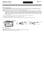
Incorrect connection:
A pole conductor was connected to the connecting terminal for neutral conductors.
Quickly disconnect the appliance from the mains!
600/550
900/825
Installation pipe
Distribution box
Clamp
400 V~ 2N
PE/ green/yellow
N blue
L1 brown
L2 black
230 V~
AUS/NZ
PE/ green/yellow
N blue
L1 brown

Installation instructions
Induction glass ceramic hob
Frameless, for flush installation
J969.123-4
10.9.12
3
Indications
• The worktop must be flat.
• In order to guarantee good ventilation, a space of at least 17.5 mm height is necessary beneath the appliance.
Fitting
1. Create an accurate installation cut-out.
– The mounting surface can be recessed by installing wood or stone bars or produced using the steel angle set (see
ZUBEHÖR).
2. Prepare the cut-out and the appliance according to the information in the accompanying cementing-in instructions.
3. Carefully cement the appliance in place and allow the silicon cement joints to dry for at least 24 hours.
4. Where necessary establish the mains supply connection before inserting the appliance.
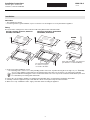
Installation
The layout of the cooking zones on the hob to be built in may differ from the illustrated hob!
GK36TIF, GK46TIF, GK36TISF, GK46TISF
GK46IDF, GK46TIMSF
GK46TIVF, GK46TIASF, GK46TIABSF
GK46IABDF, GK46TIAKSF
Access to the appliance from below must be guaranteed over the entire cut-out surface. For servicing, the induction
generator with the mounting plate can be removed from below. The covers to prevent accidental contact with live parts must
be removable by unscrewing from underneath.
477
547
737
477
743 ±1
Z
483 ±1
553 ±1
600
600/550
600
483 ±1
Z
(536/726)
(466)
R14
R0–5
600/550
825/900
0
-1
(30)
min. 55
min. 55
(30)
min. 55
min. 55
50
50
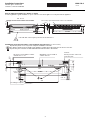
Detail Z
For symmetrical fitting
it is not necessary to
cut out the side walls.
Detail Z
Steel angle bonded or srew mounted
(for adhesive see A
CCESSORIES)
8.5 ±0.5
8.5 ±0.5
8.5
8.5
0
-0.5

Installation instructions
Induction glass ceramic hob
Frameless, for flush installation
J969.123-4
10.9.12
4
Cool air supply if installed over a drawer or cabinet
In order to guarantee good ventilation, a space of at least 17.5 mm height is necessary beneath the appliance.
Installing the protective plate with a 3 mm ventilation gap at the front (see Accessories)
A protective plate is necessary for the adequate ventilation of the hob.
The distance between the underside of the appliance and the protective plate must be at least 17.5 mm.
A protective plate cannot be installed with induction hobs that have dial controls.
min. 5
min. 15
(30)
600/550
900/825
Drawer Centre of fan
Air gap over the entire cabinet element width
min. 25 cm²
min. 48
min. 65.5
Hobs with dial control require protective intermediate base.
Necessary space below work surface for ventilation
ø4
393
min. 15
(17.5)
50
Caution:
Do not put mains cable near
protective plate
Well-fitting seal over width of
cabinet element
Air gap over entire width of cabinet
element min. 17 cm²
min. 3
(30)
min. 67.5
5.10
55.5
max. 0.5
According to template
56
Drawer
Fan
2.5
-
 1
1
-
 2
2
-
 3
3
-
 4
4


