H3C WA Series Getting Started Manual
- Category
- Networking
- Type
- Getting Started Manual


Copyright © 2010, Hangzhou H3C Technologies Co., Ltd. and its licensors
No part of this manual may be reproduced or transmitted in any form or by any means
without the prior written consent of Hangzhou H3C Technologies Co., Ltd.
The information in this document is subject to change without notice. Every effort has
been made in the preparation of this document to ensure accuracy of the contents.
However, the statements, information, and recommendations in this document do not
constitute a warranty of any kind, express or implied. Hangzhou H3C Technologies Co.,
Ltd. and its licensors shall not be liable for technical or editorial errors or omissions
contained herein.
Acknowledgments
H3C, , Aolynk,
, H
3
Care,
, TOP G, , IRF, NetPilot, Neocean,
NeoVTL, SecPro, SecPoint, SecEngine, SecPath, Comware, Secware, Storware, NQA,
VVG, V
2
G, V
n
G, PSPT, XGbus, N-Bus, TiGem, InnoVision and HUASAN are trademarks of
Hangzhou H3C Technologies Co., Ltd.
All other trademarks that may be mentioned in this guide are the property of their
respective owners.
Environmental protection
This product has been designed to comply with the environmental protection
requirements. The storage, use, and disposal of this product must meet the applicable
national laws and regulations.

Table of Contents
1 Product overview ··············································································································· 7
2 Installation preparations ······································································································ 9
Installation preparations ················································································································ 9
Preparing installation tools············································································································· 9
Examining the installation site ······································································································ 10
Installation site selection ········································································································· 10
Temperature and humidity requirements ················································································· 10
Power supply ························································································································· 10
Grounding and lightning protection ························································································ 11
3 Installing an AP ·················································································································13
4 Logging in to an AP ···········································································································14
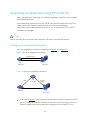
Powering on the AP and connecting it to a network ····································································· 14
Logging in to an AP ···················································································································· 15
5 Configuring basic functions ································································································16
Configuring basic functions for an AP operating in fit mode ·························································· 16
Configuring basic functions for an AP operating in fat mode ························································· 16
Specifying an IP address for an AP ·························································································· 20
Configuring WLAN service ······································································································ 20
Saving the current configuration ····························································································· 22
6 Software maintenance ······································································································24
Introduction ······························································································································· 24
Files managed by the AP ······································································································· 24
Software maintenance approaches ······················································································· 24
Bootware menus ························································································································ 26
Bootware main menu ············································································································ 26
Bootware submenus ·············································································································· 28
Factory default configuration ······································································································ 31

Factory default configuration of a fat AP················································································· 31
Removing the factory default configuration ············································································ 31
Fit/fat working mode switching ···································································································· 32
Switching the working mode through the bootware menu ······················································· 32
Switching the working mode at the CLI ··················································································· 35
Upgrading applications through the serial port ············································································· 36
Xmodem overview ················································································································ 36
Modifying serial communication parameters ··········································································· 36
Upgrading an application ······································································································ 39
Upgrading applications through TFTP at the CLI ············································································ 41
Setting up an upgrade environment ······················································································· 41
Displaying the system files and available space of the storage medium ···································· 42
Upgrading an application. ····································································································· 43
Backing up an application ····································································································· 44
Upgrading an application using FTP at the CLI ·············································································· 45
Setting up an upgrade environment ······················································································· 45
Displaying the system files and available space of the storage medium ···································· 46
Logging in to the FTP server from the AP ·················································································· 46
Upgrading an application ······································································································ 47
Backing up an application ····································································································· 47
Upgrading an application by using FTP with the default configuration ······································· 48
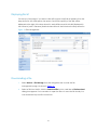
Upgrading an application through the web interface ··································································· 50
Displaying file list ···················································································································· 51
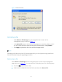
Downloading a file ················································································································ 51
Uploading a file ····················································································································· 52
Removing a file ····················································································································· 52
Automatically managing and upgrading the applications through an AC or a US ·························· 53
Associating the fit AP with an AC or a US ················································································· 53
Automatically upgrading the application of the AP through the AC or US ································· 54
Maintaining application and configuration files ············································································ 56

Displaying all files ··················································································································· 57
Setting the application file type ······························································································ 57
Removing a file ····················································································································· 58
To return to the main menu ···································································································· 59
Dealing with password loss ·········································································································· 59
User password loss ················································································································· 59
Bootware password loss ········································································································· 60
Super password loss ··············································································································· 61
7 Troubleshooting ················································································································62
Symptom 1 ································································································································ 62
Analysis ································································································································· 62
Solution ································································································································· 62
Symptom 2 ································································································································ 62
Analysis ································································································································· 62
Solution ································································································································· 63
Symptom 3 ································································································································ 63
Analysis ································································································································· 63
Solution ································································································································· 63
Symptom 4 ································································································································ 63
Analysis ································································································································· 63
Solution ································································································································· 63
Symptom 5 ································································································································ 64
Analysis ································································································································· 64
Solution ································································································································· 64
Symptom 6 ································································································································ 64
Analysis ································································································································· 64
Solution ································································································································· 64
8 Support and other resources ······························································································65
Related documentation ············································································································· 65
About the H3C WA documentation set ························································································ 66

Contact us································································································································· 67
Technical support ·················································································································· 67
Documentation feedback ····································································································· 67
Document conventions and symbols ··························································································· 68
Conventions ·························································································································· 68
Symbols ································································································································ 69

1 Product overview
Developed by Hangzhou H3C Technologies Co., Ltd (hereinafter referred to as H3C),
H3C WA series wireless local area network (WLAN) access points (APs) (hereinafter
referred to as the WA series) can be widely applied in wireless networks providing WLAN
services to users. The WA series can operate in both fat and fit modes. When they serve
as fit APs, they need to cooperate with wireless controllers or unified switches; when they
serve as fat APs, they can independently provide wireless access for WLAN users. The
WA series allow you to switch between the two modes at the CLI to accommodate to
different network sizes. Thus, flexibility is achieved.
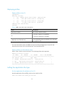
H3C WA series WLAN access points include WA2110-AG, WA2200 series, and WA2600
series. Table 1 shows the applicable models and working mode.
The WA2110-AG supports 802.11a/b/g, and serves as fit APs to cooperate with
wireless controllers or unified switches.
The WA2200 series supports 802.11a/b/g, and can switch between the fit and fat
modes to accommodate to different network sizes.
The WA2600 series supports 802.11a/b/g/n, and can operate in both fat and fit
modes. It provides an access rate of six times the traditional 802.11a/b/g network
and covers a larger area. The WA 2600 series adopts 10 GE Ethernet interfaces as its
uplink interfaces to implement wireless multi-media application.
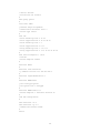
Table 1 AP model and operating mode
Series
Model
Operating in fit or fat mode
WA2110-AG
WA2110-AG
Only in fit mode
WA2200 series
WA2200 series
access points
(indoors)
WA2210-AG
Both
WA2220-AG
Both
WA2200 series
access points
(outdoors)
WA2210X-G
Both
WA2220X-AG
Both
WA2600 series
WA2600 series
access points
(indoors)
WA2610-AGN
Both
WA2612-AGN
Both
WA2620-AGN
Both
WA2600 series
WA2610E-AGN
Both

Series
Model
Operating in fit or fat mode
access points
(enhanced)
WA2620E-AGN
Both
WA2610E-GNP
Both

9
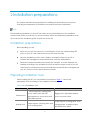
2 Installation preparations
This chapter describes the preparations for installing WA series WLAN access points,
including the preparation of installation tools and environment examination.
NOTE:
The installation preparations for the H3C WA series access points depend on the installation
environments (indoor or outdoor). For more information about the installation preparations of an
AP model, see the installation guide or quick start for the AP.
Installation preparations
Before installing your AP:
Power on your AP, and connect it to an Ethernet. Check the corresponding LED
status on your AP, and make sure that your AP works normally.
Save the installation position, MAC address, and serial number of your AP, to
facilitate the management and maintenance of APs by administrators.
Determine whether installation accessories (for example, or power adapter) are
needed according to the installation position and power supply mode of your AP.
Order them in advance because some installation accessories are not shipped with
your AP, and you need to purchase them yourself.
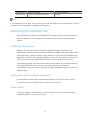
Preparing installation tools
When installing the AP, you may need the tools listed in Table 2 . Choose the
appropriate tools according to the installation environment.
Table 2 List of installation tools
Type of tool
Indoor installation
outdoor installation
General tools
1-meter-long rulers, marking pens,
knives, a percussion drill with
appropriate bits, screw driver, and
adjustable spanner
Digging tool, adjustable spanner,
vices, and screw driver
Special tools
Cable strippers, crimping pliers, and
RJ-45 crimping pliers
Cable stripper, crimping pliers, RJ-45
crimping pliers, waterproof tape,
and fiber fusion splicer

10
Type of tool
Indoor installation
outdoor installation
Auxiliary tools
Ladders and rubber hammers
Ladders
NOTE:
If you install the AP on a desk, none of the above tools are required. If you install the AP on top of
or under eave of a building, no digging tool is required.
Examining the installation site
Before installation, examine the installation site to make sure that the AP will work in a
good environment. You can examine the installation site from the following three
aspects.
Installation site selection
Keep the AP away from places that are susceptible to high temperature, dust,
inflammable, explosive, electromagnetic interference (high power radar, radio station,
and transformer), unstable voltage, heavy vibration, or loud noise. The installation site
should be dry, without any leakage, dripping, or dew. The AP should be at least 500 m
(0.31 mi) away from the seaside and should not face the direction of sea wind.
In engineering design, the site should be selected according to the network planning
and technical requirements of communications equipment, as well as the
considerations such as climate, hydrology, geology, earthquake, electric power, and
transportation.
Temperature and humidity requirements
The temperature and humidity requirements depend on your AP model. For more
information, see the installation guide or quick start of your AP.
Power supply
The power supply mode depends on your AP model. For more information, see the
installation guide or quick start of your AP.

11
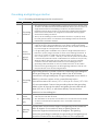
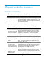
Grounding and lightning protection
Table 3 Grounding and lightning protection requirements
SN
Item
Requirements
1
Grounding
resistance
The earth resistance is usually required to be less than 5 ohms, and less than
10 ohms in an area with less than 20 thunderstorm days a year. If a piece of
angle steel is buried as the earthing conductor, the earth resistance is
required to be less than 10 ohms. In an area with a higher earth resistance,
reduce the earth resistance by using brine or resistance reducing agent
around the earthing conductor.
The top of the earthing conductor should be at least 0.7 m (2.30 ft) away
from the ground surface. In cold areas, the earthing conductor should be
buried below the frozen soil layer.
2
Device
protection
ground
(PGND)
If a grounding strip is available, connect the yellow and green ground
cable of the AP to the grounding strip. If you need to make a grounding
cable, the cable should be with a cross-section area of at least 6 mm
2
(0.24
in
2
) and a length of no longer than 3 m (9.84 ft).
If no grounding strip is available, bury a piece of angle steel/steel tube at
least 0.5 m (1.64 ft) long in the earth to serve as the earthing conductor. In
the case of a piece of angle steel, the size should be at least 50 mm × 50
mm × 5 mm (1.97 in. × 1.97 in. × 0.20 in.); in the case of a piece of steel tube,
it must be zinc-plated and have a wall thickness of at least 3.5 mm (0.14 in.).
Weld the yellow and green ground cable of the AP onto the earthing
conductor and use anti-erosion treatment on the welding joint. The
grounding cable should be as short as possible and must not be coiled.
Ensure that the grounding points of all the lightning arresters of the AP and
the peer device of the AP are well grounded.
3
Grounding
lead-in
A grounding lead-in is a metal conductor connecting a grounding net
and a grounding strip. The grounding cable of the AP should be
connected to the grounding strip. The grounding lead-in must be 30 m
(98.43 ft) or shorter. A piece of zinc-coated flat steel with a
cross-section area of 40 × 4 mm (1.57 × 0.16 in) or 50 × 5 mm (1.97 × 0.20
in) is recommended. Connect the grounding strip and the grounding
lead-in of the AP through the yellow and green ground cable with an
area of 35 mm
2
(1.38 in.), or weld them directly. Use anti-erosion
treatment on the welding joint.
4
Power
grounding
(AC)
Use a power cord with a protective earth (PE). Do not use a power cord
with only an L line and an N line.
The neutral line of the power cord should not be connected with the PGND
of other communications equipment. The L and N lines cannot be
connected
5
Lightning
arrester
In plain areas, the protection angle of the lightning rod should be less
than 45 degrees. In mountainous areas or lightning areas, the
protection angle should be less than 30 degrees. The lightning
protection grounding (for example, the grounding of the lightning rod)
should be connected to the earthing conductor of the equipment

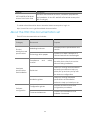
12
SN
Item
Requirements
room.
6
Feeder
The antenna support is already prepared according to the design
requirements.
A feeder lightning rod is already installed and grounded according to the
design requirements.
7
Outdoor
lightning
arrester
Power lightning arrester, port lightning protector, and feeder lightning
arrester are recommended for outdoor installations. The power
lightning arrester and the feeder lightning arrester should be near the
AP, and the network interface lightning arrester should be near the
peer device of the AP. The network interface lightning arrester should
be installed where the network cable is just led out of the room.
8
Network
cable
Use a shielded twisted pair cables for an AP used outdoors. Ensure that
the devices at the two ends of the cable are well grounded.
After you have completed the preparations, you can start installing the AP.

13
3 Installing an AP
You can directly place an indoor model (including the enhanced model) on a desk.
The rubber feet on the bottom of the AP help you to place it horizontally. Or you can fix
it onto a wall, a ceiling, or a lifting pole by using the wall-mounting bracket. Support for
the installation method depends on your AP model. For more information, see the
installation guide or quick start of your AP.
NOTE:
Some installation accessories (for example, wall-mounting brackets) are not shipped with your
AP. Determine whether to order them as needed.

14
4 Logging in to an AP
Before logging in to an AP, power on the AP and connect it to a network. For more
information, see Powering on the AP and connecting it to a network.
When an AP works in the fit AP mode, you cannot directly log in to and manage it, but
you can control it through an access controller or a unified switch associated with it.
You can use any of the following methods to log in to a WA series WLAN access point
working in the fat AP mode:
Logging in through the console port
Logging in through telnet
Logging in through SSH
Logging in through web-based network management system
Logging in through NMS
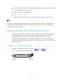
Powering on the AP and connecting it to a network
After installing the AP, perform the following steps before logging in to the AP.
1. Connect the power supply of the AP and connect it to an Ethernet.
NOTE:
For how to connect the power supply and connect your AP to a network, see the installation
guide or quick start of the AP.
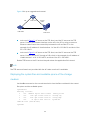
2. Check the LEDs on the AP.
Power LED
When the AP is powered on, the power LED is steady on.
If the power LED is not on, it is possibly because the AP is not powered on.
Ethernet LED
If the Ethernet LED is steady on, the AP is connected to the Ethernet.
If the Ethernet LED is blinking, the AP is connected to the Ethernet, and data is being
transmitted and received.

15
NOTE:
For the description of the LEDs on the AP, see the installation guide or quick start of the AP.
Logging in to an AP
For more information about how to log in to an AP, see Logging In to the AP in the
Fundamentals Configuration Guide in the H3C WA Series WLAN Access Points
Configuration Guides.

16
5 Configuring basic functions
The WA series WLAN access points, except for the WA2110-AG that can only operate in
fit mode, can operate in both fat and fit modes, and you can switch the operating
mode of an AP as needed.
Configuring basic functions for an AP operating in fit
mode
An AP operating in fit mode has zero configuration. When it is associated with an access
controller (AC) or unified switch (US), it does not need or save any configuration. All
configurations are performed on the AC or US.
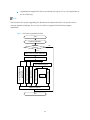
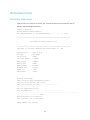
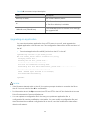
Configuring basic functions for an AP operating in fat
mode
An AP operating in fat mode has the default configuration as follows:
NOTE:
The default output depends on your AP model.
#
version 5.20, Release 1104P01
#
sysname WA2612-AGN
#
domain default enable system
#
telnet server enable
#
port-security enable
#
vlan 1
#
domain system
access-limit disable
state active

17
idle-cut disable
self-service-url disable
#
user-group system
#
local-user admin
password simple h3capadmin
authorization-attribute level 3
service-type telnet
#
wlan rrm
dot11a mandatory-rate 6 12 24
dot11a supported-rate 9 18 36 48 54
dot11b mandatory-rate 1 2
dot11b supported-rate 5.5 11
dot11g mandatory-rate 1 2 5.5 11
dot11g supported-rate 6 9 12 18 24 36 48 54
#
wlan service-template 1 clear
ssid H3C
service-template enable
#
interface NULL0
#
interface Vlan-interface1
ip address 192.168.0.50 255.255.255.0
#
interface GigabitEthernet1/0/1
#
interface WLAN-BSS32
port link-type hybrid
port hybrid vlan 1 untagged
#
interface WLAN-Radio1/0/1
service-template 1 interface wlan-bss 32
#
load xml-configuration
#
user-interface con 0
user-interface vty 0 4
authentication-mode scheme
#
return

18
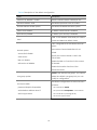
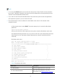
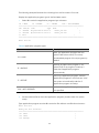
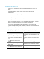
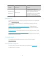
Table 4 Description of the default configuration
Field
Description
version 5.20, Release 1104P01
The AP software version currently in use
sysname WA2612-AGN
The default sysname is the AP model.
domain default enable system
The default enabled domain is system.
telnet server enable
By default, telnet server is enabled.
port-security enable
By default, port security is enabled.
vlan 1
VLAN 1 is the default VLAN, and you cannot
create and delete a default VLAN.
domain system
access-limit disable
state active
idle-cut disable
self-service-url disable
Basic configurations in the default domain
system:
The number of associated clients is not
limited.
Specify the current domain to be in the
active state.
Disable the idle-cut function for the current
ISP domain.
Disable the location function of the
self-service server.
user-group system
system is the default user group. You cannot
delete the default user group but you can
modify its configuration.
local-user admin
password simple h3capadmin
authorization-attribute level 3
service-type telnet
The default configuration of the local user is
as follows:
The username is admin.
The password is h3capadmin, case sensitive.
The user level is 3 (manage level).
The service type is telnet.

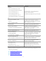
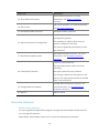
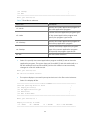
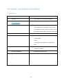
19
Field
Description
wlan rrm
dot11a mandatory-rate 6 12 24
dot11a supported-rate 9 18 36 48 54
dot11b mandatory-rate 1 2
dot11b supported-rate 5.5 11
dot11g mandatory-rate 1 2 5.5 11
dot11g supported-rate 6 9 12 18 24 36 48
54
The default 802.11a/b/g settings are as
shown on the left column.
The default rates depend on your AP model.
wlan service-template 1 clear
ssid H3C
service-template enable
By default, service template 1 with the
authentication mode open system and SSID
H3C is configured on the AP.
interface NULL0
The interface type supported by the AP.
interface Vlan-interface1
ip address 192.168.0.50 255.255.255.0
By default, the default IP address of
VLAN-interface 1 is 192.168.0.50, and the
subnet mask is 255.255.255.0.
interface GigabitEthernet1/0/1
The interface type supported by the AP.
interface WLAN-BSS32
port link-type hybrid
port hybrid vlan 1 untagged
By default, WLAN-BSS32 is a hybrid port, and
removes VLAN tags before forwarding
packets from VLAN 1.
interface WLAN-Radio1/0/1
service-template 1 interface wlan-bss 32
By default, service template 1 is associated
with radio interface WLAN BSS 32.
load xml-configuration
The AP loads the configuration file with
extension .xml after startup.
user-interface con 0
user-interface vty 0 4
authentication-mode scheme
The AP supports console and VTY user
interfaces. By default, the authentication
mode for VTY login is AAA.
Besides the default configurations, you must perform the following configurations to use
a fat AP in your network:
Specifying an IP address for an
Configuring WLAN service
Saving the current configuration

20
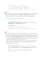
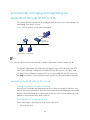
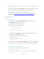
Specifying an IP address for an AP
To specify an IP address for the AP:
1. Enter system view.
<Sysname>system-view
2. Optional: Create VLANs. Using this command can create multiple VLANs in
batches.
[Sysname]vlan { vlan-id1 [ to vlan-id2 ] | all }
3. Required: Create a VLAN interface and enter VLAN interface view. If the VLAN
interface already exists, you enter its view directly. If the VLAN interface does not
exist, you need to create a VLAN and then enter VLAN interface view.
[Sysname]interface vlan-interface vlan-interface-id
4. Required: Assign an IP address to the VLAN interface. IP address 192.168.0.50 is
assigned to VLAN-interface 1 by default. No IP address is configured for other VLAN
interfaces.
[Sysname]ip address ip-address { mask | mask-length }
5. Optional: Configure the description of the current VLAN. VLAN interface name is
used by default, for example, Vlan-interface1 Interface.
[Sysname]description text
6. Optional: Bring up the VLAN interface. By default, a VLAN interface is in the up
state. In this case, the VLAN interface is up so long as one port in the VLAN is up and
goes down if all ports in the VLAN go down. An administratively shut down VLAN
interface however will be in the down state until you bring it up, regardless of how
the state of the ports in the VLAN changes.
[Sysname]undo shutdown
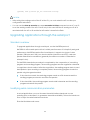
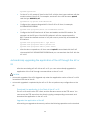
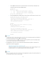
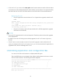
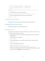
Configuring WLAN service
WLAN service configuration includes WLAN global configuration, country code, service
template, and radio configuration.
To configure WLAN service:
Enter system view.
<Sysname>system-view
Configure global WLAN parameters
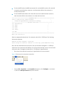
1. Optional: Specifies the time for which the link between AP and client ( power-save
or awake ) can be idle. By default, the idle timeout interval is 3600 seconds.
Page is loading ...
Page is loading ...
Page is loading ...
Page is loading ...
Page is loading ...
Page is loading ...
Page is loading ...
Page is loading ...
Page is loading ...
Page is loading ...
Page is loading ...
Page is loading ...
Page is loading ...
Page is loading ...
Page is loading ...
Page is loading ...
Page is loading ...
Page is loading ...
Page is loading ...
Page is loading ...
Page is loading ...
Page is loading ...
Page is loading ...
Page is loading ...
Page is loading ...
Page is loading ...
Page is loading ...
Page is loading ...
Page is loading ...
Page is loading ...
Page is loading ...
Page is loading ...
Page is loading ...
Page is loading ...
Page is loading ...
Page is loading ...
Page is loading ...
Page is loading ...
Page is loading ...
Page is loading ...
Page is loading ...
Page is loading ...
Page is loading ...
Page is loading ...
Page is loading ...
Page is loading ...
Page is loading ...
Page is loading ...
Page is loading ...
-
 1
1
-
 2
2
-
 3
3
-
 4
4
-
 5
5
-
 6
6
-
 7
7
-
 8
8
-
 9
9
-
 10
10
-
 11
11
-
 12
12
-
 13
13
-
 14
14
-
 15
15
-
 16
16
-
 17
17
-
 18
18
-
 19
19
-
 20
20
-
 21
21
-
 22
22
-
 23
23
-
 24
24
-
 25
25
-
 26
26
-
 27
27
-
 28
28
-
 29
29
-
 30
30
-
 31
31
-
 32
32
-
 33
33
-
 34
34
-
 35
35
-
 36
36
-
 37
37
-
 38
38
-
 39
39
-
 40
40
-
 41
41
-
 42
42
-
 43
43
-
 44
44
-
 45
45
-
 46
46
-
 47
47
-
 48
48
-
 49
49
-
 50
50
-
 51
51
-
 52
52
-
 53
53
-
 54
54
-
 55
55
-
 56
56
-
 57
57
-
 58
58
-
 59
59
-
 60
60
-
 61
61
-
 62
62
-
 63
63
-
 64
64
-
 65
65
-
 66
66
-
 67
67
-
 68
68
-
 69
69


H3C WA Series Getting Started Manual
- Category
- Networking
- Type
- Getting Started Manual
Ask a question and I''ll find the answer in the document
Finding information in a document is now easier with AI
Related papers
-
H3C WA2200 Series Fundamentals Configuration Manual
-
H3C WA2600 Series Quick start guide
-
H3C WA2610i-GN Installation guide
-
-
H3C WA2110-AG Quick start guide
-
-
-
Hewlett Packard Enterprise WA3610i-GN User manual
-
-
H3C U6IH3CEWT0235A29D User manual
Other documents
-
Dahua AWA6220-W User manual
-
HPE Networking Comware 5960 Switch Series Fundamentals Configuration Guide
-
Aruba JL588A Configuration Guide
-
Aruba Fundamentals Configuration Guide
-
ABB Smart Tool + Quick start guide
-
AirLive SNMP-GSF12M User guide
-
 RuiDeng UM25C Instructions Manual
-
 Hangzhou Ruideng Technology Co., Ltd. DPS3005 Operating instructions
-
FS SG-5110 Security Gateway Software User guide
-
ESAB PUA 1 User manual

