Page is loading ...

- 1 -
Quick Installation Guide
Version 1.2
P/N: 4041094504120P
Copyright
®
2009 All Rights Reserved.
If you have any technical diffi culties, please consult the user’s manual fi rst at:
ftp://ftp.arbor.com.tw/pub/manual
Please do not hesitate to call or e-mail our customer service when you still can not
fi nd out the answer.
http://www.arbor.com.tw
E-mail: info@arbor.com.tw
♦ Technical Support
ITX-i945EC
Mini-ITX Industrial Motherboard
Form Factor
Mini-ITX
VGA
Dual Channels LVDS/
Analog RGB /TV-out
/DVI-D
I/O
PCI/ Mini PCI/ SATA/ USB/
COM/ LPT
CPU
Socket-M for Intel®
Core™ 2 Duo/ Core™
Duo/ Pentium® M
Processor
LAN
2 x Realtek 8111B PCIe
Gigabit Ethernet
Audio
Realtek ALC655 AC97
Audio CODEC, Line-in/
Line-out/ Mic-in
Chipset
Intel® 945GME
Intel® ICH7M

- 2 -
Ordering Information
ITX-i945ECVL2G ITX-i945EC Mini-ITX industrial motherboard
Cable Kit
CBK-07-945E-00
1 x USB Cable
1 x Parallel to FDD Cable
1 x SATA Cable
1 x LPT Cable
1 x TV-out Cable
1 x IDE Cable
1 x COM Cable
Before you begin installing your single board, please make sure that the following
materials have been shipped:
Packing List
The Installation Paths of CD Driver
1
1
123
1
2
1
1
1
1 1
20
10
mPGA478 SOCKET
1
1
2
1
1
1
1
1
1
1
1
1
1
1
1
1
1
1
1 x ITX-i945EC Mini-ITX industrial motherboard
1 x CPU Cooler
1 x Driver CD
1 x Quick Installation Guide
1 x I/O bracket
Windows 2000 & XP
Driver Path
CHIPSET \CHIPSET\INTEL\INF 8.4
AUDIO \AUDIO\REALTEK_AC97\WINDOWS_A401\98_2K_XP
LAN \ETHERNET\REALTEK\8111B_WIN5686
VGA \GRAPHICS\INTEL_2K_XP_32\1432

- 3 -
Specications
Form Factor
Mini-ITX industrial motherboard
CPU
Socket-M for Intel® Core™ 2 Duo/ Core™ Duo and Pentium® M
CPU w/ FSB533/667MHz
Chipset
Intel® 945GME + Intel® ICH7M
System Memory
2 x 200-pin vertical type SO-DIMM Sockets up to 4GB DDR2
SDRAM with 400/533/667MHz
VGA/ LCD Controller
Mobile Intel® Graphics Media Accelerator 950 graphics core w/
Analog RGB/ Dual Channels LVDS/ DVI-D/ TV-Out
Ethernet
2 x Realtek 8111B PCIe Gigabit Ethernet
I/O Chips
Winbond W83627HG
BIOS
Phoenix-Award 4MB Flash BIOS
Audio
Realtek ALC655 AC97 Audio CODEC, MIC-in/ Line-In/ Line-Out,
default Line-in is absent
Support SPDIF output
Serial ATA
2 x Serial ATA with 150MB/s HDD transfer rate
Serial Port
4 x COM ports (COM1, 3, 4: RS-232, COM2: RS-232/422/485
selectable)
Parallel Port/ Floppy
1 x LPT Port (SPP/EPP/ECP mode selectable)
1 x Floppy connector, shared with Parallel Port
KBMS
PS/2 interface Keyboard and Mouse
Universal Serial Bus
8 x USB 2.0 ports (1 USB port for gaming port only)
Expansion Interface
1 x PCI Slot
1 x Mini-PCI Socket
1 x Gaming Port (Optional)
Operation Temp.
-20
o
C ~ 70
o
C (-4
o
F ~ 158
o
F)
Watchdog Timer
1~255 levels Reset
Dimension (L x W)
170 x 170 mm (6.7” x 6.7”)
Windows Vista
Driver Path
AUDIO \AUDIO\REALTEK_AC97\VISTA_6251
VGA
\GRAPHICS\INTEL_VISTA_32\1561
\GRAPHICS\INTEL_VISTA_64\156

- 4 -
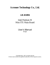
Board Dimensions
9.78
43.96
74.85
96.92
123.76
148.00
Unit: mm
6.70
26.00
31.00
1
26
50
25
1
60
31
30
120.58
10.4
0.36
Ø4.06
Ø8.99
1
1
1
1
1
123
1
2
1
1
1
2
1
1
1
20
10
1
1
2
1
1
1
mPGA478 SOCKET
1 1
1
1
1
1
6.33
157.48
33.02
10.16
132.08
170.00
154.94
170.00
2

- 5 -
Jumpers/ Connectors Quick Reference
Label Function
JCF1 Compact Flash Selection
JBAT1 Clear CMOS Setting
JVLCD1 LCD Voltage Selection
JRS1 COM2 RS-232/485 Selection
JV1
COM Port Power Special
Support
JPWR1 AT/ATX power mode
Jumpers
Label Function
CPUF1 CPU Fan Connector
IDE1 IDE Connector
SATA1~2 Serial ATA Connectors
USB1,
USB2
USB Connectors
TV1 TV-out Connector
GAMING-
BUS1
Gaming Bus Connector
SYSF1
System Fan Power
Connector
CFD1 CompactFlash Type II Socket
MINIPCI1 Mini-PCI Socket
LVDS1 LVDS Connector
JFRT1 Switches and Indicators
CON1 RS-422/485 Connector
INV1 LCD Inverter Connector
LPT1
Parallel Port (shared with
FDD Connector)
SPDIF1
Digital Audio Output
connector
AUDIO1 Audio Connector
COM1,
COM2
Serial Port Connectors
LAN1,
LAN2
Ethernet RJ-45 + Double
stack USB type A Connectors
VGA1
Analog RGB + DVI-D
Connectors
KBM1
Keyboard & Mouse
Connector
COM3,
COM4
Serial Port Connectors
SO-DIMM1,
SO-DIMM2
SO-DIMM Sockets
PW1 ATX Power Supply Connector
Connectors

- 6 -
Jumpers & Connectors Location
1
1
123
1
2
1
1
1
1 1
20
10
mPGA478 SOCKET
1
1
2
1
1
1
1
1
1
1
1
1
1
1
1
1
1
1
PW1
JPWR1
32
31
SO-DIMM1
SO-DIMM2,
30
VGA1
26
LAN2 LAN1
2425
COM2
COM1
23
AUDIO1
22
CPUF1
IDE1
USB2
USB1
GAMINGBUS1
TV1
JCF1
JBAT1
SYSF1
CFD1
MiniPCI1
LVDS1
JFRT1
JVLCD1
JRS1
CON1
INV1
LPT1
JV1
SPDIF1
SATA1,
S ATA 2
1
2
3
4
5
6
7
8
9
10
11
12
13
14
15
16
17
18
19
20
21
KBM1
27
COM4
COM3
28
29

- 7 -
Jumpers
Connectors
JBAT1: Clear CMOS Setting (9)
Connector type: 2.54mm pitch 1x3-pin headers.
Pin Mode
1-2 Keep CMOS (Default)
23 1
2-3 Clear CMOS
23 1
JVLCD1: LCD Panel Voltage Selection
(15)
The voltage of LCD panel could be selected by
JVLCD1 in +5V or +3.3V.
Connector type: 2.54mm pitch 1x3-pin headers.
Pin Voltage
1-2 +5V
23 1
2-3 +3.3V (Default)
23 1
JPWR1: AT/ATX Power Mode (31)
Connector type: 2.54mm pitch 1x2-pin headers.
Pin Mode
Short AT mode
1 2
Open ATX Mode (Default)
1 2
JRS1: COM2 RS-232/422/485 Selection
(16)
Connector type: 2.00mm pitch 2x3-pin headers.
Mode
RS-232
(Default)
RS-422 RS-485
1-2 Short Open Open
3-4 Open Short Open
5-6 Open Open Short
65
2
1
65
2
1
65
2
1
JV1: COM1 Port Power Special
Support (20)
Connector type: 2.54mm pitch 1x3-pin headers.
Pin Mode
1-2 pin-1 is +5V
23 1
2-3 pin-1 is DCD# (Default)
23 1
CPUF1: CPU Fan Connector (1)
CPUF1 is a 3-pin headers for the CPU fan. The fan
must be a +12V fan.
Pin Description
1
2
3
1 GND
2 +12V
3 FAN_Detect
JCF1: CF IDE1 Mode Master/ Slave
Selection (7)
Connector type: 2.54mm pitch 1x2-pin headers.
Pin Mode
Short Master (Default)
1 2
Open Slave
1 2
IDE1: Primary IDE Connector (2)
Connector type: 2.54mm pitch 2x20 box headers.
1 2
39 40
Pin Description Pin Description
1 IDE RESET 2 GND
3 DATA7 4 DATA8
5 DATA6 6 DATA9
7 DATA5 8 DATA10
9 DATA4 10 DATA11
11 DATA3 12 DATA12
13 DATA2 14 DATA13
15 DATA1 16 DATA14
17 DATA0 18 DATA15
19 GND 20 N/C (Key)
21 REQ 22 GND
23 IO WRITE 24 GND
25 IO READ 26 GND
27 IO READY 28 IDSEL
29 DACK 30 GND
31 IRQ14 32 N/C
33 ADDR1 34 ATA66 DETECT
35 ADDR0 36 ADDR2
37 CS#1 38 CS#3 (HDSELECT1)
39 IDEACTP 40 GND

- 8 -
SYSF1: System Fan Connector (10)
SYSF1 is a 3-pin headers for the CPU fan. The fan
must be a +12V fan.
Pin Description
1
2
3
1 GND
2 +12V
3 FAN_Detect
USB1, 2: USB Connectors (4, 5)
Connector type: 2.54mm pitch 2x5-pin headers.
USB1:
Pin Desc. Pin Desc.
1
2
10
9
1 +5V 2 +5V
3 USBD- 4 USBD-
5 USBD+ 6 USBD+
7 GND 8 GND
9 GND 10 N/C (Key)
USB2:
Pin Desc. Pin Desc.
1
2
10
9
1 +5V 2 +5V
3 USBD- 4 N/C
5 USBD+ 6 N/C
7 GND 8 GND
9 GND 10 N/C (Key)
SATA1~2: Serial ATA Connectors (3)
High speed transfer rates (150MB/s).
Pin Description
1
7
1 GND
2 TX+
3 TX-
4 GND
5 RX-
6 RX+
7 GND
GAMINGBUS1 : Gaming Bus
Connector on bottom side (8, Optional)
Pin Description Pin Description
1 GND 31 AGND
2 GND 32 LINE-L
3 GND 33 LINE-R
4 GND 34 AGND
5 GND 35 GPIO
6 PCIE-CLK0+ 36 PCI_CLK
7 PCIE-CLK0- 37 GND
8 GND 38 GND
9 PCIE-TX0+ 39 GND
10 PCIE-TX0- 40 GND
11 GND 41 SCLK
12 PCIE-RX0+ 42 SDATA
13 PCIE-RX0- 43 +3.3V
14 GND 44 +3.3V
15 USB0+ 45 +3.3V
16 USB0- 46 +3.3V
17 GND 47 +3.3V
18 PSON# 48 N/C
19 5VSB 49 N/C
20 5VSB 50 +5V
21 N/C 51 +5V
22 N/C 52 +5V
23 GND 53 +5V
24 LFRAME# 54 +5V
25 LRESET# 55 PWRBTN#
26 LAD0 56 +12V
27 LAD1 57 +12V
28 LAD2 58 +12V
29 LAD3 59 +12V
30 SERIRQ 60 +12V
1 30
31 60
TV1: TV-out Connector (6)
Connector type: 2.00mm pitch 1x6-pin box wafer
connector
Composite Video
1
CVBS
2 GND
3
Unused
4 GND
5
Unused
6 GND
S-Video
1
Unused
2 GND
3
Luminance
4 GND
5
Chrominance
6 GND
Note: one of the USB ports is for gaming port only.

- 9 -
MINIPCI1 : MiniPCI Socket (12)
LVDS1: LVDS LCD Connector (13)
Connector type: DF-13-30DP-1.25V connector and
supports dual channel
.
Pin Desc. Pin Desc.
1
2930
2
2 VDD 1 VDD
4 TX2CLK+ 3 TX1CLK+
6 TX2CLK- 5 TX1CLK-
8 GND 7 GND
10 TX2D0+ 9 TX1D0+
12 TX2D0- 11 TX1D0-
14 GND 13 GND
16 TX2D1+ 15 TX1D1+
18 TX2D1- 17 TX1D1-
20 GND 19 GND
22 TX2D2+ 21 TX1D2+
24 TX2D2- 23 TX1D2-
26 GND 25 GND
28 TX2D3+ 27 TX1D3+
30 TX2D3- 29 TX1D3-
JFRT1: Switches and Indicators (14)
It provides connectors for system indicators that
provides light indication of the computer activities
and switches to change the computer status.
Connector type: 2.54mm pitch 2x8-pin headers.
1
2
16
15
Pin Description Pin Description
1 Power LED+ 2 PWRBTN-
3 GND 4 PWRBTN+
5 GND 6 RESET+
7 HDD LED+ 8 RESET-
9 HDD LED- 10 SPEAKER+
11 SMB_CLK 12 SPEAKER+
13 SMB_DATA 14 SPEAKER-
15 GND 16 SPEAKER-
CFD1 : CompactFlash Disk Socket (11,
on bottom side and shared with IDE1)
Note:
1. CF Socket supports up to 16GB.
2. CF Socket does not support Hot Swap.
3. CF and ATA channel are alternative.
Pin Description Pin Description
1 GND 26 CF_Detect
2 PDD3 27 PDD11
3 PDD4 28 PDD12
4 PDD5 29 PDD13
5 PDD6 30 PDD14
6 PDD7 31 PDD15
7 PDCS1# 32 PDCS3#
8 GND 33 N/C
9 GND 34 PDIOR#
10 GND 35 PDIOW#
11 GND 36 +5V
12 GND 37 PIDEIRQ
13 +5V 38 +5V
14 GND 39 CSEL#
15 GND 40 N/C
16 GND 41 IDERST#
17 GND 42 PIORDY
18 PDA2 43 PDDREQ
19 PDA1 44 PDDACK#
20 PDA0 45 HD_LED1#
21 PD0 46 PDIAG#
22 PD1 47 PDD8
23 PD2 48 PDD9
24 N/C 49 PDD10
25 N/C 50 GND

- 10 -
SPDIF1: Digital Audio Output (21)
Connector type: 2.54mm pitch 1x4-pin headers.
Pin Description
1
2
3
4
1 +5V
2 N/C (Key)
3 SPDIF_O
4 GND
AUDIO1: AC97 AUDIO Connector (22)
Connector type: double stacks audio jacks (Stereo
ø3.50).
Pink: Mic
Green: Line Out
COM1, COM2: Serial Port Connectors (23)
Connector type: Double stacks D-Sub 9-pin male.
Pin Desc. Pin Desc.
1 5
96
1 5
96
1 DCD# 6 DSR#
2 RXD 7 RTS#
3 TXD 8 CTS#
4 DTR# 9 RI#
5 GND
Note:
The COM1 port’s pin-1 could be selected by JV1
respectively to +5V or DCD#.
LAN1, LAN2: 1 x RJ-45 + 2 x USB (24, 25)
Connector type: RJ-45 + double stacks USB type A
connector.
LAN (RJ-45)
LED
LED
LAN
USB
USB
8 7 6 5 4 3 2 1
1 2 3 4
1 2 3 4
Pin Desc. Pin Desc.
1 MDI0+ 5 MDI2+
2 MDI0- 6 MDI2-
3 MDI1+ 7 MDI3+
4 MDI1- 8 MDI3-
USB (USB type A
connector)
Pin Desc.
1 +5V
2 USB-
3 USB+
4 GND
CON1: RS-422/485 Output Connector
(17)
Connector type: 2.00mm pitch 1x4 box wafer
connector.
Pin RS-422 RS-485
1
2
3
4
1 TX+ DATA+
2 TX- DATA-
3 RX+ N/C
4 RX- N/C
INV1: LCD Inverter Connector (18)
Connector type: 2.00mm pitch 1x5 box wafer
connector.
Pin Description
1
2
3
4
5
1 +12V
2 GND
3 Backlight on/off
4 Brightness control
5 GND
LPT1: Parallel Port Connector (19)
Connector type: 2.00mm pitch 2x13-pin headers.
(Share w/ FDD connector)
Pin Description Pin Description
1
10
2
20
1 STB# 2 AFD#
3 PTD0 4 ERROR#
5 PTD1 6 INIT#
7 PTD2 8 SLIN#
9 PTD3 10 GND
11 PTD4 12 GND
13 PTD5 14 GND
15 PTD6 16 GND
17 PTD7 18 GND
19 ACK# 20 GND
21 BUSY 22 GND
23 PE 24 GND
25 SELECT 26 N/C

- 11 -
PW1: ATX Power Connector (32)
Pin Desc. Pin Desc.
111
1020
11 +3.3V 1 +3.3V
12 -12V 2 +3.3V
13 GND 3 GND
14 PS-ON 4 +5V
15 GND 5 GND
16 GND 6 +5V
17 GND 7 GND
18 N/C 8 PW-OK
19 +5V 9 +5VSB
20 +5V 10 +12V
VGA1: Analog RGB & DVI-D
Connectors (26)
Connector type: VGA: D-Sub 15-pin female.
DVI-D: DVI-D female.
Analog RGB
DVI-D
1
1
8
17
24
5
1115
Analog RGB Connector
Pin Description Pin Description
1 RED 9 +5V
2 GREEN 10 GND
3 BLUE 11 N/C
4 N/C 12 VDDAT
5 GND 13 HSYNC
6 GND 14 VSYNC
7 GND 15 VDCLK
8 GND
DVI-D Connector
Pin Description Pin Description
1 TMDS Data 2- 13 N/C
2 TMDS Data 2+ 14 +5V
3
TMDS Data 2/4
shield
15 GND
4 N/C 16 Hot plug detect
5 N/C 17 TMDS Data 0-
6 DDC clock 18 TMDS Data 0+
7 DDC data 19
TMDS Data 0/5
shield
8 N/C 20 N/C
9 TMDS Data 1- 21 N/C
10 TMDS Data 1+ 22
TMDS Data clock
shield
11
TMDS Data 3+
shield
23 TMDS clock+
12 N/C 24 TMDS clock-
KBM1: PS/2 Keyboard & Mouse (27)
Standard PS/2 Keyboard & Mouse connector
Connector type: double stack 6-pin mini DIN.
Pin Description
78
9
1112
10
Keyboard
(Purple)
12
3
56
4
Mouse
(Green)
1 KB Data
2 N/C
3 GND
4 +5V
5 KB Clock
6 N/C
7 MS Data
8 N/C
9 GND
10 +5V
11 MS Clock
12 N/C
COM3~4: RS-232 Connectors (29, 28)
Connector type: 2.54mm pitch 2x5 box-pin headers.
Pin Desc. Pin Desc.
109
1 2
1 DCD# 2 RXD
3 TXD 4 DTR#
5 GND 6 DSR#
7 RTS# 8 CTS#
9 RI# 10 N/C

- 12 -
This page is intentionally left blank.
/