Installation and operating manual
Décember 2017

2
1 - GENERAL
It is advisable to read it carefully so you will save time during
operations.
Follow the indications so you will not cause damages to things
and injuries to people
Before going ahead with operations, read the GENERAL
WARNINGS .
Pay particular attention to :
WARNING, identifies particularly important operations or
information
PROHIBITIONS, identifies operations that must not be
carried out, that compromises the operating of the unit or
may cause damages to persons or things.

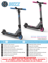
Consider sound emissions
Aeraulic ducts
Avoid air bypass
Avoid installations next to
bedrooms
✓
A
Should not be tilted towards unit
Remote electric panel
B
** Insulated ducts
Install in a local or compartment where the temperature can't drop below 0 ° C.
For details see the manual
sections
Size 200-300 650
A (mm) 666 710
B (mm) 760 993
Anti-vibration joint when used rigid pipes
Size 200-300 650
A Air expulsion Ø 200 mm Ø 250 mm
B
Ambient air
return
Ø 200 mm Ø 250 mm
C
Ambient air
distribution
Ø 200 mm Ø 250 mm
D
Fresh air
intake
Ø 200 mm Ø 250 mm
Filter size 200-650
RCW15 ambient thermostat
C
Connect the ambient thermostat to the terminal block of the
customer connections
Terminal block of
the customer
Connections
Cable 3x0,34 mm
2
shielded
Max. length 80 m
Unit fixing points
Install supplied antivibration
Dimensions connections

Condensate discharge
Quick guide
Space to access:
* 700 - filter access from below, electrical panel on
board unit
* 200 - filter access from below, remote electrical
panel
Sloping tube
D
Avoid tight bends
Safety grilles
BEFORE REQUESTING START-UP
Completed system
Completed aeraulic system and free of dirt
Electric connections
!
AE fresh air intake
ES air expulsion
M ambient air distribution
R ambient air return
If there are electric heaters,
increase access space
Trapdoor opening
Sifón
** extraction air filter from below
Insulated ducts
Size
A B
200-300 310 276
650 370 336
Positions thermostat
The thermostat must be placed:
• at a height of 150 cm
• preferably on an internal wall
• Positions to avoid:
• next to heat sources
• points exposed to direct
sunlight
• Ecc….
Pag. 22/26/30
Ceiling access
Airflow 2020

5
1 - GENERAL
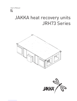
1.1 UNIT DESCRIPTION
1 Serial number label
2 Exhaust air fan
It rejects the unhealthy air outdoors.
3 Internal exchanger
It transfers energy (heat / cool) to the fresh air .
4 Compressor
5 Supply fan
It blows treated air in the rooms.
7 Electrical remote panel
It is possible to remove the electrical panel and
make it remote to facilitate the installation
8 External exchanger
It recovers energy (heat / cool) from the exhaust air.
9 Air filter
It purifies the fresh air before introducing it into the
rooms
10 Upper panel
11 Electronic filter (option)
12 Electrical panel
1.2 ACCESSORIES
Electronic filter kit
Kit of exhaust air filter
Serial communication module to supervisor (MODBUS)
Airflow 2020
Is the air distribution system.

6
1.3 UNIT IDENTIFICATION
Serial number label
The serial number label is positioned on the unit, generally next to the electrical panel, and allows you to indentify all
the unit features.
The serial number label has not to be removed for any reason.
It reports the regulations indications such as:
• Type of unit
series → AW-AIRFLOWxxx-N11
• size → 200.......650
• serial number
xxxxxxxxxxxx
• year of manufacture
• wiring diagram number
• electrical data
• manufacturer logo and address
Serial number
It identifies uniquely each unit.
It identifies specific spare parts for the unit.
Intervention requests
Note data from the serial number label and write them in the table sideways, so you will find them easily when needed.
In case of intervention you have to provide the data indicated sideways.
Serie
Size
Serial number
Year of manufacture
Wiring diagram
1 - GENERAL

7
Lifting with forks:
• Insert the forks as indicated in the figure.
• During the handling is forbidden to exceed the maximum allowable inclination
as indicated in the figure.
• It is forbidden to lift simultaneously more packages letting them looses.
• In case of lifting of more units at the same time, an appropriate container must
be used.
2 - RECEPTION
Before accepting the delivery you have to check:
• that the unit hasn’t been damaged during transport
• that the materials delivered correspond with that
indicated on the transport document comparing the
data with the identification label ‘A’ positioned on the
packaging.
In case of damage or anomaly:
• write down on the transport document the damage you
found and quote this sentence: "Conditional
acceptance — clear evidence of deficiencies/damages
during transport".
• Contest by fax and registered mail with advice of
receipt to supplier and the carrier.
Any disputes must be made within the 8 days owing the
delivery. Complaints after this period are invalid.
Packaging removing
• Cut the fixing strips.
• Remove the packaging lifting it upwards.
2.1 DELIVERY CONTROL
A
AIRFLOW 2020

8
2 - RECEPTION
2.2 KIT REMOVAL
AIRFLOW 2020
The unit is supplied in a single pack and is equipped with:
1 installation manual
2 installation kit - Ambient thermostat
Installation kit
A spring antivibrations n.4
B M8 nuts n.4
C plain washers n.4
D toothed washers n.4
E M8 bolts n.4
F ambient thermostat

9
3 - POSITIONING
The unit has been designed to be installed :
• indoor
• in fixed position
The unit can not be installed outdoor or in a room /
compartment where the temperature can drop
below 0 ° C.
Installation criteria:
• safe accessible position
• customer approval
• avoid flood-prone places;
• verify the unit weight and bearing point capacity;
• verify that all bearing points are aligned and lev-
elled
• unit in bubble level
• plan in the false ceiling (or in the floor) the open-
ings indicated in the functional clearances to allow
the access to the unit for the maintenance opera-
tions
• Ceiling positioning : let free the projection to the
ground of the unit and of the functional clearances
to allow the access with ladders or other means
• Floor positioning : install the unit raised from the
ground .
Limit vibration transmission:
• use antivibration devices on unit bearing/
supporting points
• install flexible joints on the hydraulic/aeraulic con-
nections.
The functional clearances have to :
• guarantee the unit good operating
• allow the maintenance operations
• safeguard the authorized operators and the ex-
posed person.
• position the unit taking into consideration the clear-
ances indicated in the figure.(following pages)
• consider the space necessary for return ambient
filter extraction (see option).
3.1 CLEARANCE ACCESS RECOMMENDED
UNIT IN BUBBLE LEVEL
Consider sound emissions
Avoid installations next to bedrooms
Size 200-300 650
A (mm) 666 710
B (mm) 760 993
UNIT FIXING POINTS

10
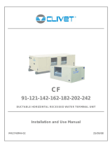
3 - POSITIONING
Mod L1A L1B L1C L L2 W1 W W2
200 700 mm 400 mm 200 mm 920 mm 20 mm 300 mm 704 mm 300 mm
300 700 mm 400 mm 200 mm 920 mm 20 mm 300 mm 704 mm 300 mm
650 700 mm 400 mm 200 mm 1158 mm 20 mm 300 mm 741 mm 300 mm
AIRFLOW 2020
AE fresh air intake
ES air expulsion
M Ambient air distribution
R Ambient air return
AIRFLOW 2020
A Space to access the electrical panel
B Space necessary for the by-pass damper
C Distance to prevent vibrations from being transmitted
(insert a neoprene sheet)
D Trap door for routine maintenance (access to electrical
panel and optional electronic filter)
E Access to conduct extraordinary maintenance (to
replace the fan, compressor, etc.)
F Access to fan removal
G Access to clean the filter (exhaust air filter - option)
Heat. el. = If there are heating elements, increase the W1
value
A
B
C
G
D
A
F
G
F
Heat. el.
L1A ceiling installation, filter access from below, non-remote electrical control board at a distance
floor installation, lateral filter access, non-remote electrical control board at a distance
L1B floor installation, lateral filter access, remote electrical control board at a distance
L1C ceiling installation, filter access from below, remote electrical control board at a distance
E

11
• Fix some M8 threaded bars (not supplied) to the
ceiling.
• Pass the M8 threaded bars in the brackets on the
unit.
• Insert and screw on the tapped bar the spring
antivibration device.
• The antibration device must be positioned with the
interior threaded downward
• Insert the flat and notched washer and screw the
nut to lock.
• Avoid to over tighten the nuts, the springs, because
if too much crushed they don’t absorb vibrations.
• Insert the M8 threaded bar on the support base.
• Match the upper hole of the antivibration device
with the hole of the support bracket.
• The antibration device must be positioned with the
interior threaded upward.
• Insert the flat and notched washer in the bolt.
• Screw the bolt in the top of the antivibration device
letting it pass through the hole on the bracket.
• Do not over tighten the nuts, the springs, because if
too much crushed they don’t absorb vibrations
3 - POSITIONING
3.2 CEILING POSITIONING 3.3 FLOOR POSITIONING
A threaded bar
B bracket
C antivibration foot
D flat washer
E notched washer
F nut
A bolt
B notched washer
C flat washer
D bracket
E antivibration foot
F threaded bar

12
The electrical panel is provided assembled on the unit side but if necessary it
can be remotely controlled up to 2 mt. away.
325
252
120
Electric panel
3 - POSITIONING
3.4 ELECTRIC PANEL
Remote positioning
• Unscrew the fixing screws and remove the electrical panel cover.
• Unscrew the fixing screws (M6) and remove the panel from the unit side.
• Fix the panel using screws and screw anchors suitable for the characteristics of the used support.
• If later it is supposed the installation of the electric elements (optional) consider that the cable to connect to the
electrical panel has a max length of 1,5 metres.
• In this case the filter removal for cleaning can be performed either from the side or from below.
L = 2mt
3.5 ACCESS TO INTERNAL PARTS
Access from the upper side Access from the bottom side

13
3 - POSITIONING
3.6 AMBIENT THERMOSTAT
21.0
REMOTE
ECO
AUTO
E
c
o
C
l
e
a
n
The choice of the installation point is decisive for the
environmental comfort and the energy consumption.
The thermostat must be placed :
• In a room with medium temperature and humidity
conditions, representative of the other rooms
• at a height of 150 cm
• preferably on an internal wall
Positions to avoid :
• next to heat sources
• points exposed to direct sunlight
• in a position with air rejected from outlets or
diffusers
• behind curtains or pieces of furniture
• near windows and doors to the outside
• on walls crossed by fireplaces or heating ducts
• on external walls.

14
4 - WATER CONNECTIONS
4.1 CONDENSATE DISCHARGE
4.2 RISK OF FREEZE
The condensate must be disposed in order to avoid
damages to people and things.
• Unit discharge fitting: the connection must not
transmit mechanical stresses and must be
performed taking care not to damage the unit
discharge fitting.
• Provide a siphon that, eliminating the negative
pressure caused by the fan, prevents the air intake
from the discharge duct.
• The ducting must have a min. slope of 5% to allow
the runoff.
• Anchor the ducting with an adequate number of
supports.
• Otherwise are generated duct failures and air locks
that prevent the runoff.
• Insulate the duct and the siphon to avoid the
condensate drippings.
• Connect the condensate discharge to a sewerage
drainage network. DO NOT use white water or
drainage networks to avoid the aspiration of odours
in the case of evaporation of water contained in the
siphon.
• The connection must not be hermetic, so as to
allow the venting and avoid possible liquid returns.
• Check at the end of the work, the regular
condensate runoff pouring some water in the tray.
Prevent the risk of freeze if the unit, drain or plumbing
connections of the humidifier can be subject to
temperatures close to 0°C.
For example:
• safeguard the pipes with heating cables placed
under the insulation .
• insulate the pipes.
• perform the installation draining if unused for long
periods.
• provide the antifreeze resistance in case of rigorous
temperatures.
A Condensate discharge fitting Ø 26 mm
Condensate discharge pump - option
A
P
H
S
T
Example:
P = 100 Pa = 10 mm
T = 2P = 20 mm
S = T/2 = 10 mm
Siphon height calculation
T = 2P
S = T/2
P is the pressure determined by the fan in
correspondence of
the condense collection bowl (approx. 1 mm = 9.81 Pa)
Siphon

15
5 - AERAULIC CONNECTIONS
Size 200-300 650
A Air exhaust Ø 200 mm Ø 250 mm
B Ambient air return Ø 200 mm Ø 250 mm
C Ambient air distribution Ø 200 mm Ø 250 mm
D Fresh air intake Ø 200 mm Ø 250 mm
5.2 AIR DISTRIBUTION / EXHAUST SYSTEM
5.1 AERAULIC DESIGN CRITERIA
The dimensioning and the correct execution of the aeraulic connections are critical to ensure the unit operating and an
appropriate level of quietness in the served area.
Here are some indications, as a simple checklist to support the installer and the designer of the installation.
• AIR RENEWALS = 0,5 volumes per hour , max 1 volume per hour ; in the volume are not considered the extraction
rooms (kitchens, bathrooms, etc.)
• AIR SPEED included between 2 and 3 m/sec (it guarantees the system silence)
• RETURN AIR in the kitchens / bathrooms / rooms with vapours, unpleasant odours
• SUPPLY AIR in the living room , bedrooms , studies etc....
If the duct outlets for the outdoor air inlet and exhaust are outside of coverage, must end with a 90 ° bend downward, to
prevent entry of water from the air inlet.
To perform the ductings:
• Connect the ductings fixing them to the connections with the special hookings to the circular flanges.
• The duct weight should not lie on the connection flanges.
• Put antivibration joints between ducts and units.
• The connection to the flanges and among the different duct sections must guarantee the air seal, avoiding air
dispersions in supply and return that penalize the overall efficiency of the installation.
• Limit the pressure drops by optimizing the path, the type and the number of curves and branches.
• Use curves of large radius.
• Thermically insulate the supply ducts to avoid heat losses and condensate.

16
Install :
1. on the fresh air intake of the grid (to prevent small
animals or leaves from entering)
2. on the ambient air exhaust of the grid (to prevent
small animals or leaves from entering)
3. on the ambient air return of the filter to avoid soiling
the coil (size 200-650)
5 - AERAULIC CONNECTIONS
The ducts should not be tilted towards unit to avoid the
condensate and water return.
A. Thermically insulate the supply ducts to avoid heat
losses and condensate.
B. Avoid tight bends, pressure drops
Avoid recirculation of exhaust/return air
✓
Insulated ducts
2
Exhaust/return grille (GR150X - GR200X - GR250X)
Size A B
200-300 310 276
650 370 336
✓
1
3
Accessory separately supplied

17
6 - ELECTRIC CONNECTIONS
6.1 ELECTRICAL CONNECTION DIAGRAM
Access :
1. Unscrew the panel screws
2. Identify the control
3. Make a hole in the cable sleeve
4. Remove the jumper (P)on the terminal block if
the control is used
5. The control connect
XC
REMOTE CONTROLS
CUMLATIVE BLOCK
CONDENSATE
DISCHARGE
RCW15
BLACK
GRAY
BROWN
BLUE
Refer to the unit electrical diagram

18
6 - ELECTRIC CONNECTIONS
xc
Remote summer-winter selector switch (heat/cool)
It allows the change of the operating mode from
heating to cooling from an external control.
• Set parameter 161
= 0 only from keypad/thermostat
= 1 control only from remote control
On - Off
Remove the jumper 12cn1 and 12a on the XC terminal
block
• Set parameter 162 :
= 0 only from keypad/thermostat
= 1 control only from remote control
Silent
It reduces the fan speed.
• Set parameter 224
= 0 disabled
= 1 from digital input
= 2 digital / supervisor input
Ventilation (fan)
Only the fans are actives and no check on the
temperature and humidity is performed ( compressor,
humidifier and resistances are disabled).
Fire signalling (alarm AI)
In case of alarm signalling from a fire surveying station,
the unit can put the ambient:
- in negative pressure
- in pressure
- maintains a neutral ambient
Set parameter 91 :
= 0neutral ambient
= 1 depressurized ambient
= 2 ambient in pressure
Remove the jumper 11cn1 and 3cn1 on the XC
terminal block.
Connect the alarm signalling to terminals 11cn1 and
3cn1.
Cumlative block
Unit blocked signal
RCW15 AMBIENT THERMOSTAT
Connect the RCW15 ambient thermostat as indicated
in the figure.
Connections :
• 3x0,34mm
2
shielded
• max. length 80 m
RCW15 - REMOTE CONTROL WITH TOUCH SCREEN DI-
SPLAY
Remote user keypad, to control the unit main functions.
To use the keyboard, you need:
• 7ACEL1733 - 12Vdc power supply unit (supplied
separately)
• serial communication module
(supplied separately)
For details, see instructions accessory.
RCW15 opt.
Pressing any button of the thermostat there is not
control / communication check the fuses (FU 12v and
FU NET).
If the fuses are burnt replace them and check the
connections.

19
6 - ELECTRIC CONNECTIONS
Remote control inputs
REMOTE ELECTRIC PANEL - AIRFLOW 2020
POWER SUPPLY
The holes for passing the electric lines are present on
the electric panel.
To connect:
• Remove the hole protection cover
• Pull the cable up to the connection terminal
• Carry out the connection in accordance with the
electric connection layout
• Ensure that the cable is correctly inserted and
blocked in the clamp.
Fastening holes of the eletric panel
AP1 Main control module KAC Compressor control relay
AP exp Expansion module KAfiltr. Relay
DGS Manual reset button (Compressor protection) T1 Aux. circuit transformer
FU1 Compressor fuse RS485 Serial communication module
FUX 230v auxiliary circuit protection fuse XCR
Connection of the service keypad
FU 12v Protection fuse 12v (AP1) 5x20 T 160mA XRS Connection of the preheating resistances
FU NET Protection fuse NET (AP1) 5x20 T 50mA X1 Terminal block of the Customer connections
PE
N
L
There are 2 card (AP1) protection fuses ( FU 12v and FU NET) in order to protect itself from any connection errors of the RCW15
Keypad
RCW19

20
6 - ELECTRIC CONNECTIONS
X1
Remote summer-winter selector switch (heat/cool)
It allows the change of the operating mode from
heating to cooling from an external control.
• Set parameter 161
= 0 only from keypad/thermostat
= 1 control only from remote control
On - Off
Remove the jumper 12cn1 and 12a on the X1 terminal
block
• Set parameter 162 :
= 0 only from keypad/thermostat
= 1 control only from remote control
Silent
It reduces the fan speed.
• Set parameter 224
= 0 disabled
= 1 from digital input
= 2 digital / supervisor input
Ventilation (fan)
Only the fans are actives and no check on the
temperature and humidity is performed ( compressor,
humidifier and resistances are disabled).
Fire signalling (alarm AI)
REMOTE CONTROLS
HUMIDIFIER OPTION
Refer to the unit electrical diagram (the number of the diagram is shown on the serial number label).
Remove the jumper (P) on the terminal block if the control is used
The control connect
RCW19
Page is loading ...
Page is loading ...
Page is loading ...
Page is loading ...
Page is loading ...
Page is loading ...
Page is loading ...
Page is loading ...
Page is loading ...
Page is loading ...
Page is loading ...
Page is loading ...
Page is loading ...
Page is loading ...
Page is loading ...
Page is loading ...
Page is loading ...
Page is loading ...
Page is loading ...
Page is loading ...
Page is loading ...
Page is loading ...
Page is loading ...
Page is loading ...
Page is loading ...
Page is loading ...
Page is loading ...
Page is loading ...
Page is loading ...
Page is loading ...
Page is loading ...
Page is loading ...
Page is loading ...
Page is loading ...
Page is loading ...
Page is loading ...
Page is loading ...
Page is loading ...
Page is loading ...
Page is loading ...
Page is loading ...
Page is loading ...
Page is loading ...
Page is loading ...
Page is loading ...
Page is loading ...
Page is loading ...
Page is loading ...
Page is loading ...
Page is loading ...
Page is loading ...
Page is loading ...
Page is loading ...
Page is loading ...
Page is loading ...
Page is loading ...
Page is loading ...
Page is loading ...
Page is loading ...
Page is loading ...
/