Page is loading ...

Part Number 104370-102 Release Date 07/2005
NEO 8000
TM
Scalability Upgrade
Installation Guide

ii X Part Number 104370-102 07/2005
Proprietary Notice
All information contained in or disclosed by this document is considered proprietary by Overland
Storage. By accepting this material, the recipient agrees that this material and the information
contained therein are held in confidence and in trust and will not be used, reproduced in whole or in
part, nor its contents revealed to others, except to meet the purpose for which it was delivered. It is
understood that no right is conveyed to reproduce or have reproduced any item herein disclosed
without express permission from Overland Storage. Overland Storage provides this manual as is,
without warranty of any kind, either expressed or implied, including, but not limited to, the implied
warranties of merchantability and fitness for a particular purpose. Overland Storage may make
improvements or changes in the products or programs described in this manual at any time. These
changes will be incorporated in new editions of this publication.
Overland Storage assumes no responsibility for the accuracy, completeness, sufficiency, or usefulness
of this manual, nor for any problem that might arise from the use of the information in this manual.
Overland products are covered by one or more of the following patents registered with the USPTO:
5,870,245; 6,328,766; 6,353,581; 6,496,325.
Worldwide Headquarters Overland Storage, Inc.
4820 Overland Avenue
San Diego, CA 92123
Toll Free: (800) 729-8725
Tel: (858) 571-5555
Fax: (858) 571-3664
Sales Tel: (858) 571-5555
Fax: (858) 571-3664
E-mail: [email protected]
www.overlandstorage.com
Technical Support Tel: (858) 571-5555
Fax: (858) 571-3664
Toll Free: (877) 654-3429
E-mail: [email protected]
Overland Storage, EMEA Overland House, Ashville Way
Wokingham, Berkshire
RG41 2PL, England
Tel: +44 (0) 118-9898000
Fax: +44 (0) 118-9891897
www.overlandstorage.com

104370-102 07/2005 W iii
Preface
Overview
This installation guide provides instructions and information required for installing an
Overland Storage Horizontal Robotics Assembly (HRA) in a NEO 8000™ library system
comprised of two library units. It assumes you are familiar with basic functions of your
computer and networking.
Manual Organization
The following information is contained in this manual.
Chapter 1, “Introduction.”
Provides an overview of the change-out process, along with a brief description of any
additional recommendations.
Chapter 2, “Prepare the Libraries.”
Describes how to open up the libraries to facilitate the removal and replacement of the HRA.
Chapter 3, “Remove the Old HRA.”
Discusses the processes needed to disconnect and physically remove the HRA.
Chapter 4, “Install the New HRA.”
Details the steps required to install and connect the new HRA in the library system.
Chapter 5, “Verify the HRA Operation.”
Covers the processes to power up the libraries and verify that the replacement was a
success.

iv X 104370-102 07/2005
PREFACE
Conventions
This user guide exercises several typographical conventions.
Overland Storage Technical Support
For more assistance, search for help at:
http://support.overlandstorage.com/
Our Overland Storage Technical Support staff is also available to assist you by phone at:
1.877.654.3429 (Toll-free and active only in US and Canada)
1.858.571.5555 x5 (Worldwide)
On normal business days 6 AM through 5 PM (California time) excluding Overland holidays.
At all other times we will respond to technical support calls within 4 hours.
Technical support for our European customers is available as well from our United Kingdom
office at:
+44 (0) 118-9898050
9:00 am to 5:00 pm (GMT)
Monday through Friday
You can e-mail our technical support staff at [email protected].
Convention Description & Usage
Boldface Words in boldface indicate items to select such as menu items or
command buttons.
Ctrl-Alt-r This type of format details the keys you press simultaneously. In this
example, hold down the Ctrl and Alt keys and press the r key.
NOTE A Note indicates neutral or positive information that emphasizes or
supplements important points of the main text. A note supplies
information that may apply only in special cases—for example, memory
limitations or details that apply to specific versions of a program.
IMPORTANT An Important note is a type of note that provides information essential
to the completion of a task or that can impact the product and its
function. Users can disregard information in a regular note and still
complete a task, but they should not disregard an important note.
CAUTION A Caution contains information that the user needs to know to avoid
damaging or permanently deleting data or causing physical damage to
the hardware or system.
WARNING A Warning contains information essential to people’s safety. It
advises users that failure to take or avoid a specific action
could result in physical harm to the user or hardware.

104370-102 07/2005 W v
Table of Contents
Preface
Overview ...................................................................................................................................... iii
Manual Organization .................................................................................................................. iii
Conventions .................................................................................................................................iv
Overland Storage Technical Support .......................................................................................iv
Chapter 1 - Introduction
Installation Process Overview ..................................................................................................1-1
Required Tools ..................................................................................................................... 1-2
Suggested Items ................................................................................................................. 1-2
HRA Parts Locations .................................................................................................................. 1-2
Electrostatic Discharge Information ....................................................................................... 1-3
Chapter 2 - Pre-Installation Processes
Conduct the Site Survey .......................................................................................................... 2-1
Verify Minimum Firmware Level .............................................................................................. 2-1
Obtaining the Current Firmware File ................................................................................ 2-3
Removing Components for Access ....................................................................................... 2-3
Remove Media Drawers .................................................................................................... 2-4
Power Down the Libraries .................................................................................................. 2-4
Remove Side Panels ........................................................................................................... 2-4
Remove Library Doors ........................................................................................................ 2-5
Remove Components for Rear Access ............................................................................ 2-6
Chapter 3 - Prepare the Libraries
Verify Cable Channel Status ................................................................................................... 3-1
Install the HRA Mounting Brackets .......................................................................................... 3-1
Verify the Mail Slot PWA ........................................................................................................... 3-3
Install the Master Signal Cable ................................................................................................3-6
Install the Master Power Wiring Harness ................................................................................. 3-7
Install the Slave Signal Cable .................................................................................................. 3-9
Install the Slave Power Wiring Harness ................................................................................. 3-11
Chapter 4 - Connect the Libraries
Install the Connector Bolts ....................................................................................................... 4-1
Position and Level the Master Unit .......................................................................................... 4-2
Position and Level the Slave Unit ............................................................................................ 4-3
Confirm Mounting Bracket Assembly Alignment .................................................................. 4-4
Tighten Connecting Hardware ............................................................................................... 4-4
Complete the Slave Wiring Routing ....................................................................................... 4-5
Chapter 5 - Install the HRA
Attach the HRA ......................................................................................................................... 5-1
Install the VIA Router Card ...................................................................................................... 5-3
Prepare the Library System for Use ......................................................................................... 5-5
Chapter 6 - Configure the System
Power Up the Library System ................................................................................................... 6-1

vi X 104370-102 07/2005
TABLE OF CONTENTS
Configure the Library System ...................................................................................................6-1
Reinstall Library Components ..................................................................................................6-3
Appendix A - Troubleshooting
Robotics Hangs .........................................................................................................................A-1
Lost Contact with Slave Unit ...................................................................................................A-1
Library Unit Fails to Get Cartridge from HRA ......................................................................... A-1
Slave Unit Not Recognized ......................................................................................................A-2
Index

104370-102 07/2005 W vii
List of Figures
Chapter 1 - Introduction
Figure 1-1: HRA Major Components ........................................................................................ 1-2
Chapter 2 - Pre-Installation Processes
Figure 2-1: Clearance Needed for HRA Installation .............................................................. 2-1
Figure 2-2: Power Strip Circuit Breakers ................................................................................... 2-2
Figure 2-3: Power Supply Power ON/OFF Switch ON Position............................................... 2-2
Figure 2-4: NEO 8000 Front Panel ............................................................................................. 2-2
Figure 2-5: Verify Minimum Firmware Level............................................................................. 2-3
Figure 2-6: Library Panel Cover Removal Example................................................................ 2-5
Figure 2-7: Example Removing Door Hinge Pin...................................................................... 2-5
Figure 2-8: Access Plates and Drives That Need To Be Removed ....................................... 2-6
Chapter 3 - Prepare the Libraries
Figure 3-1: Cable Channel After Modification....................................................................... 3-1
Figure 3-2: Mounting Bracket Assembly for HRA (D-clamps Attached).............................. 3-2
Figure 3-3: Positioning the Mounting Bracket Assembly........................................................ 3-2
Figure 3-4: Location of Mounting Bracket Screw Holes......................................................... 3-3
Figure 3-5: Magazine Latch Assembly Location .................................................................... 3-4
Figure 3-6: Old and New Mail Slot PWA .................................................................................. 3-5
Figure 3-7: Mail Slot PWA Replacement.................................................................................. 3-5
Figure 3-8: Location of Fan/Card Cage Assembly ................................................................ 3-6
Figure 3-9: Master Signal Cable Connection ......................................................................... 3-7
Figure 3-10: Location of Robotics Power Supply Bay Power Cords ..................................... 3-8
Figure 3-11: Robotics Power Supply Bay Screws .................................................................... 3-8
Figure 3-12: Power Supply Bay Assembly Connectors........................................................... 3-9
Figure 3-13: Slave Signal Cable Connection........................................................................ 3-10
Figure 3-14: Rear of Slave Unit Showing Wiring Exiting Access ........................................... 3-11
Chapter 4 - Connect the Libraries
Figure 4-1: M8x100mm Bolt Locations on Master Unit Braces............................................... 4-1
Figure 4-2: Bolt Pushed Back Through Brace .......................................................................... 4-2
Figure 4-3: Marking Reference Points for a Front Leveler...................................................... 4-2
Figure 4-4: Placement of Small Level on Slide Housing ......................................................... 4-3
Figure 4-5: Hex Bolt and Nuts After Tightening ....................................................................... 4-4
Chapter 5 - Install the HRA
Figure 5-1: HRA Positioned Above the Mounting Bracket Assemblies................................. 5-1
Figure 5-2: Mounting Bracket Alignment Pins ......................................................................... 5-1
Figure 5-3: Screw Locations to Attach the HRA to the Brackets .......................................... 5-2
Figure 5-4: HRA PWA Connectors ............................................................................................ 5-3
Figure 5-5: Inserting the VIA Router Card into the Master Library ........................................ 5-4
Figure 5-6: VIA 8-port Router Card........................................................................................... 5-4
Chapter 6 - Configure the System
Figure 6-1: Configure Slave Unit ............................................................................................... 6-1
Figure 6-2: Configure Master Unit............................................................................................. 6-2


104370-102 07/2005 W 1–1
Chapter 1: Introduction
The NEO 8000 architecture can be expanded by adding second library unit. A Horizontal
Robotics Assembly (HRA) is installed inside the two connected NEO 8000 libraries to enable
the robotics in each of the individual libraries to exchange cartridges by means of a pass-
through system. This results in a system that integrates the robotics of the individual units
into a single high-performance library robotics system.
IMPORTANT: Overland Storage recommends that the Horizontal Robotics Assembly be installed
by an Overland Storage authorized service provider. Improper installation may result in damage
to this part or the library components which would void all existing warranties.
Installation Process Overview
Described below are the major steps required to install the HRA in your NEO 8000 system.
Unless otherwise noted, all hardware is included in the HRA kit.
NOTE: Always retain any screws removed during this procedure. They will be reused to reinstall
the appropriate components.
Step 1: Pre-Installation Processes
• Conduct the Site Survey to verify space and distance requirements.
• Verify that the minimum firmware level is installed.
• Remove various panels and drawers to enable easy access inside the libraries.
Step 2: Prepare the Libraries
• Confirm the intermediate cable channels are cut to allow room for the HRA.
• Install the Mounting Bracket assemblies for the HRA.
• If needed, install new Mail Slot Printed Wiring Assembly (PWA) board.
• Add motor wiring harnesses and signal cables to both libraries for the HRA.
Step 3: Connect the Libraries
• Attach and level the two library units.
• Complete the routing of the wiring.
Step 4: Install the HRA
• Install the HRA in the combined library units and connect the wiring.
• Run cables from the VIA router to the Master and Slave Library Controller cards.
• Replace all components removed for internal access.
Step 5: Configure the System
• Power On both units.
• Configure the Master and Slave units using the Graphical User Interface (GUI).
• Test the HRA operational ability.

1–2 X 104370-102 07/2005
INTRODUCTION
Required Tools
These tools are required for the proper removal and replacement of the HRA.
• #1 and #2 Phillips Screwdrivers
• #2 Stubby Phillips Screwdriver
• 6" or 10" Spirit Level (15cm or 25cm)
• 36" Level with Straight Edge (90cm)
• Diagonal Cutting Pliers
• 2 each M13 Combination Wrenches
• M3 Hex Key
• 10" Adjustable Wrench (260mm)
• Tape Measure
Suggested Items
Some additional items that might be helpful are listed below.
• Masking Tape
• Bold Marker
• Pry Bar
• Wrench Tethers
• Extra D-type cable clamps and tie-downs
HRA Parts Locations
Figure 1-1 shows the layout of the HRA major components.
Figure 1-1: HRA Major Components
N
E
O
-
8
0
9
7
a
J
5
J
7
J
8
J
4
J
3
J
1
J
2
J
6
HRA Controller PCB
Shuttle
Signal/Power Flex Harness
Shuttle Controller PCB

104370-102 07/2005 W 1–3
INTRODUCTION
Electrostatic Discharge Information
A discharge of static electricity can damage static-sensitive devices. Proper packaging and
grounding techniques are necessary precautions to prevent damage. To prevent electrostatic
damage, observe the following precautions.
• Transport products in static-safe containers such as conductive tubes, bags, or boxes.
• Keep electrostatic-sensitive parts in their containers until they arrive at static-free
stations.
• Cover the library with approved static-dissipating material.
• Use a wrist strap connected to the work surface and properly-grounded tools and
equipment.
• Keep the work area free of non-conductive materials such as foam packing materials.
• Make sure you are always properly grounded when touching a static-sensitive
component or assembly.
• Avoid touching pins, leads, or circuitry.

1–4 X 104370-102 07/2005
INTRODUCTION

104370-102 07/2005 W 2–1
Chapter 2: Pre-Installation Processes
The HRA is intended to be physically mounted between two NEO 8000 libraries. An HRA kit
may include the following:
• Site Survey
• Factory-assembled HRA
• Mounting Bracket assembly components
• Replacement Mail Slot PWA with an additional connector for the HRA sensor
• Signal Cable and Power Wiring Harness for each library
IMPORTANT: It is recommended that all NEO 8000 libraries in a multi-unit library system use the
same drive types. If you want to mix drive types in the multi-unit library system, check with your
application software vendor to manage partitioning by tape technology.
Conduct the Site Survey
Using the Site Survey packed with the HRA unit, verify that there is at least 3.5 feet (1.1m)
of clear space beside the library (see Figure 2-1) to allow enough room to insert the HRA
after the libraries are positioned and leveled. The space can be on either side but it is
recommended to insert the HRA on the Master unit side. Also, be sure there is enough space
on all the other sides to allow access to the units through the panel openings.
Figure 2-1: Clearance Needed for HRA Installation
Verify Minimum Firmware Level
The first models of the NEO 8000 produced did not incorporate the functionality required for
the SmartScale Storage
TM
architecture operation. The minimum firmware level needed to
operate a multi-module configuration is Firmware Version 4.05. To verify the firmware
level of the Master module, do the following:
N
E
O
-
8
1
0
5
N
E
O
-
8
1
0
5
3.5 feet
MasterSlave

2–2 X 104370-102 07/2005
PRE-INSTALLATION PROCESSES
1. If the library is powered off, turn it ON.
a. Set both circuit breakers to the ON position (see Figure 2-2).
Figure 2-2: Power Strip Circuit Breakers
b. Set each power supply’s ON/OFF switch to the ON position (“|”) (see Figure 2-3).
Figure 2-3: Power Supply Power ON/OFF Switch ON Position
c. At the front of the library, press anywhere on the GUI touch screen or press the
Power ON/OFF button to apply power to the library.
Figure 2-4: NEO 8000 Front Panel
O
N
O
N
O
N
O
N
ONOFF
N
E
O
-
8
0
8
5
N
E
O
-
8
1
0
7
Switch in the
ON Position
ON/OFF Switch GUI Screen

104370-102 07/2005 W 2–3
PRE-INSTALLATION PROCESSES
2. After the POST completes, press Menu > Library Info.
The firmware revision appears in the Miscellaneous Library Info window (see
Figure 2-5).
Figure 2-5: Verify Minimum Firmware Level
If the firmware in the Master library is less than Version 4.05, it should be upgraded before
continuing with the installation of the HRA. (In Figure 2-5, the firmware needs to be
upgraded from 2.01 to 4.05.)
Obtaining the Current Firmware File
The latest release of the firmware can be obtained from the Overland Storage ftp site.
1. Point your browser to: ftp://ftp.overlandstorage.com/outgoing/nextgen.
2. Download the latest firmware file neo8000_nnn.bin (were “nnn” represents the
latest version number).
3. Use WebTLC or Neo8000Center to upgrade the firmware.
Refer to the Overland NEO 8000 Library User Guide for details.
Removing Components for Access
To simplify the installation of the HRA and related cabling, you need to remove various
doors, panels, and drawers to allow access to all key areas inside the library unit.
Verify the Version Number

2–4 X 104370-102 07/2005
PRE-INSTALLATION PROCESSES
Remove Media Drawers
Release and remove media drawers and Master Mail Slot magazine to provide internal
access. Label the drawers so that they can be returned to the same library and location.
WARNING: Exercise care when removing the media drawers from the library units.
Fully-loaded drawers weigh approximately 58 pounds (26.3 kg).
1. On the Master unit, release and remove the following items.
• Top-right media drawer
• Middle-right media drawer
• Mail Slot magazine
2. On the Slave unit, release and remove the following items.
• Top-left media drawer
• Middle-left media drawer
• Mail Slot magazine
Store the drawers in a safe place until ready to reinsert them.
Power Down the Libraries
WARNING: Working with a powered NEO 8000 library may cause physical harm and
severe damage to unit’s circuitry. Always power down a library before removing any
panels.
1. Power down both units at the front panel.
2. Set each of the library circuit breakers to the OFF (“O”) position.
3. Remove and retain the power cords.
Remove Side Panels
Remove both side panels from both libraries.
1. At the Master unit, remove the screws (six hex or eight phillips) that secure the right
panel and carefully remove the panel (see Figure 2-6).

104370-102 07/2005 W 2–5
PRE-INSTALLATION PROCESSES
Figure 2-6: Library Panel Cover Removal Example
2. Remove the screws that secure the left panel and carefully remove it (see Figure 2-6).
3. Repeat Steps 1–2 for the Slave unit.
Remove Library Doors
Remove both the front and rear doors on both units.
1. At the front of the Master unit, open the left door, remove the two hinge pins and
nylon washers (upper and lower), and then carefully remove the door. (see Figure 2-
7).
Figure 2-7: Example Removing Door Hinge Pin
N
E
O
-
8
0
9
0
N
E
O
-
8
0
9
1

2–6 X 104370-102 07/2005
PRE-INSTALLATION PROCESSES
CAUTION: Be sure to note the number of nylon washers between each particular set of hinge
blocks and retain them. Failure to reinstall the proper number of washers between their
respective hinge blocks may cause the door to not operate properly.
2. Open the right door, remove the two hinge pins and nylon washers (upper and
lower), and carefully remove the door.
3. Repeat Steps 1–2 to remove the front doors on the Slave unit.
4. Remove the rear doors from both units by lifting them off their hinges.
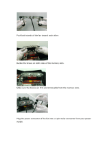
Remove Components for Rear Access
Remove various access plates and tape drives from both libraries to allow easier access.
Figure 2-8: Access Plates and Drives That Need To Be Removed
1. From the rear of the Master unit, remove these items.
• left-center access plate
• right-center access plate
2. From the rear of the Slave unit, remove these items.
• left-center access plate
• right-center access plate
• right-upper access plate
• Drives 5, 6, 11, and 12 (or their blank covers) and their center dividers.
N
E
O
-
8
1
0
5
N
E
O
-
8
1
0
5
Access Plates
MasterSlave
Access Plates
Drives/Covers
& Divider
Drives/Covers
& Divider
Access Plate

104370-102 07/2005 W 3–1
Chapter 3: Prepare the Libraries
This section prepares the two libraries for the installation of the HRA by installing the
additional wiring and mounting brackets.
Verify Cable Channel Status
On earlier production units, the plastic cable channel at the right-rear of the Master unit
was one piece. It must be modified to accommodate the HRA (see Figure 3-1).
Figure 3-1: Cable Channel After Modification
1. On the Master library, inspect the right-rear cable channel.
• If the channel is one single piece, continue with Step 2.
• Otherwise, skip to section titled “Install the HRA Mounting Brackets.”
2. Carefully remove the section of cable channel between these points.
• Bottom of the Robotics Power Supply bay
• Top of Power Supply bay for Drives 1–6.
CAUTION: Be sure to avoid damage to the wires in the channel.
3. Add cable ties if needed to keep the wires from interfering with the HRA.
Install the HRA Mounting Brackets
The Mounting Bracket assemblies come partially assembled as two pieces for shipping
purposes. They need to be assembled and then mounted in the rear of the libraries.
Robotics Power
Supply Bay
Drive 1-6 Power
Supply Bay
Cable Channel
(After Cutting)

3–2 X 104370-102 07/2005
PREPARE THE LIBRARIES
1. Use four M4x8mm screws from the Mounting Bracket kit to attach the upright
bracket to the base assembly (see Figure 3-2).
Figure 3-2: Mounting Bracket Assembly for HRA (D-clamps Attached)
2. Mount two 0.50" (1.27cm) D-type cable clamps with the open side up on the rear of
a Mounting Bracket assembly.
NOTE: Be sure the clamps do not extend above the top edge of the assembly.
3. Repeat Steps 1–2 for the other assembly.
4. Position a Mounting Bracket assembly against the Master front bulkhead with the
assembly alignment pins in the bulkhead holes (see Figure 3-3).
Figure 3-3: Positioning the Mounting Bracket Assembly
NOTE: Reroute/realign any wires that could interfere with the operation of the HRA.
N
E
O
-
8
0
9
9
D-clamps
Base
Assembly
Upright
Bracket
M4x8mm
Screws
Mounting
Bracket
Mounting
Holes
/