Page is loading ...

- 1 -
600T EN Series
HART Pressure Transmitters
Models 6X1ED - EE - EH - EG - EA
Models 622ED, 6X1ES
Operating instructions

- 2 -
Health and Safety
To ensure that our products are safe and without risk to health, the following points must be noted:
1. The relevant sections of these instructions must be read carefully before proceeding.
2. Warning labels on containers and packages must be observed.
3. Installation, operation, maintenance and servicing must only be carried out by suitably trained personnel and in accordance with the
information given.
4. Normal safety precautions must be taken to avoid the possibility of an accident occurring when operating in conditions of high
pressure and/or temperature.
5. Chemicals must be stored away from heat, protected from temperature extremes and powders kept dry. Normal safe handling
procedures must be used.
6. When disposing of chemicals ensure that no two chemicals are mixed.
Safety advice concerning the use of the equipment described in this manual or any relevant hazard data sheets (where applicable) may
be obtained from the Company address on the back cover, together with servicing and spares information.
The Company
ABB Automation is an established world force in the design and manufacture of
instrumentation for industrial process control, flow measurement, gas and
liquid analysis and environmental applications.
As a part of ABB, a world leader in process automation technology, we offer
customers application expertise, service and support worldwide.
We are committed to teamwork, high quality manufacturing, advanced
technology and unrivalled service and support.
The quality, accuracy and performance of the Company’s products result from
over 100 years experience, combined with a continuous program of innovative
design and development to incorporate the latest technology.
The NAMAS Calibration Laboratory No. 0255(B) is just one of the ten flow
calibration plants operated by the Company, and is indicative of ABB
Automation’s dedication to quality and accuracy.
Use of Instructions
Warning.
An instruction that draws attention to the risk of injury or
death.
Caution.
An instruction that draws attention to the risk of damage
to the product, process or surroundings.
R
E
G
I
S
T
E
R
E
D
F
I
R
M
BS EN ISO 9001
St Neots, U.K. – Cert. No. Q5907
Stonehouse, U.K. – Cert. No. FM 21106
Stonehouse, U.K. – Cert. No. 0255
UNI EN 29001 (ISO 9001)
Lenno, Italy – Cert. No. 9/90A
Although Warning hazards are related to personal injury, and Caution hazards are associated with equipment or property
damage, it must be understood that operation of damaged equipment could, under certain operational conditions, result in
degraded process system performance leading to personal injury or death. Therefore, comply fully with all Warning and
Caution notices.
Information in this manual is intended only to assist our customers in the efficient operation of our equipment. Use of this manual
for any other purpose is specifically prohibited and its contents are not to be reproduced in full or part without prior approval
of Technical Communications Department, ABB Automation.
✶
Note.
Clarification of an instruction or additional information.
Information.
Further reference for more detailed information or
technical details.
ABB AUTOMATION
Year 2000 compliance
600T EN Series products have no impact due to year 2000, operating as follows:
• the Year 2000 date format will be "00";
• the date is used only as caption, no calculation are done on date in the products, comparisons on dates are not supported in the
products;
• the products continue to work in the correct manner;
• the product send to the connected systems the correct information;
• if the products receive an input that it is not compatible with Year 2000 there are not damages or faults to the products themselves.

- 3 -
Section Page
INTRODUCTION............................................................3
TRANSPORT, STORAGE, HANDLING AND
PRODUCT IDENTIFICATION........................................4
PRINCIPLE OF OPERATION ........................................5
INSTALLATION..............................................................7
ELECTRICAL CONNECTIONS .....................................8
ELECTRICAL REQUIREMENTS ................................11
RANGE AND SPAN CONSIDERATION ......................11
CALIBRATION .............................................................12
DISMANTLING AND REASSEMBLY ..........................14
SIMPLE FAULT FINDING............................................15
RETURNING FORM ....................................................16
ADDENDUM FOR "METERS" OPTION OF
THE TRANSMITTERS .................................................17
ADDENDUM FOR COMETER - ANALOG LCD
INDICATOR WITH HART PROGRAMMING
CAPABILITY ................................................................20
ADDENDUM FOR PV-SCALING OPERATION...........25
ADDENDUM FOR "SURGE PROTECTOR" OPTION
OF THE TRANSMITTERS ...........................................26
ADDENDUM USE OF HARDWARE LINKS
ON THE SECONDARY ELECTRONICS .....................30
ADDENDUM FOR DIFFERENTIAL PRESSURE
TRANSMITTERS : SELECTABLE OUTPUT
FUNCTIONS ................................................................33
ADDENDUM FOR FLANGE-MOUNTED
TRANSMITTERS .........................................................39
ADDENDUM FOR "EX SAFETY" ASPECTS
AND "IP" PROTECTION (EUROPE) ...........................45
CONTENTS
INTRODUCTION
The 600T series is a modular range of field mounted, micro-
processor based electronic transmitters, using a unique
inductive sensing element. Accurate and reliable
measurement of differential pressure, gauge and absolute
pressure, flow and liquid level is provided, in the even most
difficult and hazardous industrial environments.
The 600T Smart series transmitter now includes an Analog
Version (4-20 mA analog output), an Analog Version plus
HART digital communication and a Profibus DP-PA Version.
Digital communication protocols, HART and Profibus, allow
remote re-ranging, calibration and diagnostics.
With respect to HART, the bidirectional digital communication
does not have any interference with the standard 4-20 mA
analog output signal.
Profibus has a complete digital only communication.
This manual describes the features, the installation and
calibration procedures related to the 600T Series Transmitter
with HART Communication Protocol.
SUPPLEMENTARY DOCUMENTATION
Reference information on remote seals and configuration of
the transmitter can be found in the following documents:
SS / S6 Rev. 6 Remote Seal Specification
IM / 691HT Rev. 1 Hand-Held Communicator
Online HELP SMARTVISION Configuration Program

- 4 -
Important - The instrument serial number must always be quoted when making enquiries.
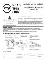
PRODUCT IDENTIFICATION
The instrument is identified by the data plates shown in
Figure 1.
The Nameplate (ref.A) provides information concerning the
code number, maximum working pressure, range and span
limits , power supply and output signal. See code/specification
sheet for detailed information. This plate also shows the
transmitter serial number. Please refer to this number when
making enquiries.
A dedicated label (ref. B) is welded as standard to the primary
unit, carrying specific details of the transducer (diaphragms
material, fill fluid, range limit and identification number).
A Safety Marking plate ( ref. C) is fitted when the transmitter
is required to comply with hazardous area regulations, e.g.
flameproof or intrinsic safety protection. Additionally Tag plate
(ref. D) provides the customer tag number and calibrated
range; this is screwed on the housing and can be removed to
be wired-on by the supplied stainless steel wire.
Fig. 1 - Product identification
Ref. B
Primary Unit
Ref. A
TRANSPORT
After final calibration, the instrument is packed in a carton
(Type 2 to ANSI/ASME N45.2.2-1978), intended to provide
protection from physical damage.
STORAGE
The instrument does not require any special treatment if
stored as despatched and within the specified ambient
conditions level (Type 2 to ANSI/ASME N45.2.2-1978).
There is no limit to the storage period, although the terms of
guarantee remain as agreed with the Company and as given
in the order acknowledgement.
HANDLING
The instrument does not require any special precautions
during handling although normal good practice should be
observed.
Ref. C
Ref. D
Ref. D
Ref. A
DIN TYPE
HOUSING
BARREL TYPE
HOUSING
SERIAL
NUMBER
URL
DIAPHRAGM
MATERIAL
FILL
FLUID
Pushbuttons below label

- 5 -
The instrument consists of two functional units:
- Primary Unit
- Secondary Unit
The Primary Unit includes the process interface and the
sensor, the Secondary Unit includes the electronics, the terminal
block and the housing. The two units are mechanically coupled
by a threaded joint. The Electronics of Secondary Unit is based
on custom integrated components (Application Specific
Integrated Circuit - ASIC).
Resin potting
Primary Electronics
Printed Circuit
Sensor Diaphragm
with Ferrite Disks
Process
chamber
Capillary tubing
Inductance Coils
& Magnetic
Cores
Isolating
diaphragm
Fig. 2a - Primary Unit
PRINCIPLE OF OPERATION
The principle of operation of the Primary Unit is as follows. The
process fluid ( liquid, gas or vapour ) exerts pressure on to the
sensor diaphragm via flexible, corrosion-resistant isolating
diaphragms and capillary tubing containing the fill fluid (see
Fig. 2a).
As the sensor diaphragm deflects in response to differential
pressure changes, it simultaneously produces variations in the
gap between two fixed magnetic circuits (comprising coil and
ferrite core) positioned on both sides of the measuring
diaphragm. As a result, the inductance of each coil changes.
The two inductance values L1 and L2, and the sensor
temperature ST are combined in the primary electronics to
provide a proprietary standardized signal.
In the manufacturing process the sensor output characteristics
are compared with reference pressures and temperatures: the
"mapped" parameters are then stored in the memory of Primary
electronics.
The measured values and the sensor parameters are transferred
to the Secondary Unit, where a microprocessor computes
precise primary output linearisation, compensating for the
combined effects of sensor non linearity, of static pressure and
temperature changes. In the secondary electronics permanent
memory are stored the transmitter specific information:
- non modifiable data such as the serial number, the UID
(Unique Identifier), the manufacturer's name and device type,
the hardware and software version of the electronics.
- the modifiable data such as the final trimming and calibration,
in other words, all data that can be changed by the user
through the configuration devices.
External Zero/Span
adjustments
Fig. 2b - Secondary Unit
Output meter
(option)
Surge protector
(option)
Terminal
block
Housing Electronics
Integral meter
(option)
RFI filter
Capillary tubing
Process
chamber
Isolating
diaphragm

With secondary electronics analog and analog+HART, it is to
be consider that different communication protocols exist for
configuration and maintenance operations. Here follows a
brief description on the matter; please refer to appropriate
technical specification for additional deeper explanations on
the communication aspects.
The HART protocol is based on the standard Bell 202 FSK
(Frequency Shift Keying ) with a ±0.5 mA signal modulation
superimposed on the 4 to 20 mA analog signal. As the energy
balance added to the current loop is virtually zero and the
frequency is very high compared to that of the process dynamic,
the analog process signal remains undisturbed. Using a
configuration device it is then possible to remotely modify the
configuration of the transmitter, e.g. the measuring range.
. . . PRINCIPLE OF OPERATION
Internal Serial Bus
Parallel Bus
SENSOR
INTERFACE
DIGITAL
CONVERTER
MICRO
CONTROLLER
EXT. ADJ
INTERFACE
MEMORY
4 to 20 mA
CONVERSION
MEMORY
Primary electronics
(located in the
Primary Unit)
Sensors
Internal bus
Fig. 3 - Functional Block Diagram (Analog + HART version)
MODEM FSK
COUPLER
Zero
Span
Secondary Electronics
(located in the
Secondary Unit)
4 to 20 mA
Output
For the ANALOG version the microprocessor computers the 4
to 20 mA output signal.
For the ANALOG + HART version, in addition to the 4 to 20 mA
output signal, the microprocessor also receives data from the
internal modem, in order to provide bidirectional digital
communication with the configuration device, i.e. the Hand
Held terminal "Communicator" or P.C. based "Configurator".
It is also possible to read other transmitter data and diagnostic
information. Limited rezeroing and respanning, comparable to
that conventional analog transmitters is possible using the
optional calibration device. Refer to Fig. 3 for a complete view
of the Functional Block Diagram.
The sensor and all electronic parts are galvanically isolated
from the transmitter body.
For the analog version the Function Block Diagram is the same
as the one represented in Fig. 3, but without the MODEM - FSK
COUPLER box for HART signal generation.
- 6 -

INSTALLATION
- 7 -
Fig. 6 - Mounting on 2" horizontal pipe
CAUTION - Proper location of the transmitter
with respect to the process pipe will depend upon the
service for which the instrument is used. Care should be
exercised to identify correct process connections.
The secondary unit of the transmitter may be rotated through
360° approx. with respect to the primary unit without
degrading performance or damaging the internal wiring. Do
not force the primary unit to rotate; use the 2 mm Allen key
supplied to unlock and lock the tang grub screw (see Fig. 7).
This feature, obtained by unscrewing (one turn is sufficient)
the Allen screw, is particularly useful for reaching optimum
access to the electrical connections and visibility of the output
indicator.
Fig. 4 - Process Connections
(Diff. Press. Transmitter)
WARNING
In order to ensure operator safety and plant safety
it is essential that installation is carried out by
suitably trained personnel according to the techni-
cal data provided in the specification for the
relevant model.
The transmitter may be mounted on a vertical or horizontal 2-
inch pipe (figg. 5 and 6) by means of the same mounting
bracket.
Note: for other installation details see the relevant
Addendum.
Fig. 5 - Mounting on 2" vertical pipe
Note: High side may be marked H or +
Low side may be marked L or -
WARNING - For installation in Hazardous Areas,
i.e. areas with dangerous concentrations of e.g. gases or
dusts that may explode if ignited, the installation must be
carried out in accordance with relative standards either
EN 60079-14 or IEC 79-14 and/or with local authority
regulations, for the relevant type of protection adopted.
Together with safety information here and after enclosed
see also the Addendum for "Ex Safety" aspects which is
part of this instruction manual.
WARNING: The transmitter when installed in
accordance with this instruction manual will not be
subjected to mechanical stresses.
WARNING: the transmitter should not be installed
where it may be subjected to mechanical and thermal
stresses or where it may be attached by existing or
foreseable aggressive substances.
+

- 8 -
WARNING - For installation in Hazardous Areas,
i.e. areas with danger of fire and/or explosion, prior to
making electrical connections, ensure compliance with
safety information on the Safety Marking plate. Failure to
comply with this warning can result in fire or explosion.
Signal terminals are located in a separate compartment of the
secondary unit housing. The housing incorporates two con-
nection ports for cable glands or conduit fittings. They are
protected with a temporary plastic plug for transit purpose
which should be replaced with a suitable permanent plug in the
unused port. Connections can be made by removing the cover
(indicated in Fig. 7); first screw down the locking screw located
below the cover, using a 3 mm Allen Key.
WARNING - For Hazardous Areas installations,the
connection of cables and conduits to the transmitter shall
be made in accordance with the requirements of the
relevant type of protection. Cables and cable-glands
must be in accordance with the type of protection.
Unused openings for connection shall be closed with
blanking elements suitable for the relevant type of
protection. With the exception of intrinsically safe
transmitters, the means provided for this shall be such
that the blanking element can be removed only with the
aid of tools. The blanking elements must be certified for
the type of protection. See standards either EN 60079-14
or IEC 79-14. The transmitter connections must also
guarantee the degree of protection of the transmitter
enclosure, e.g. IPxx according to EN 60529 standard (or
IEC529). See also the Addendum for "IP" protection (and
Ex Safety) which is part of this instruction manual.
The signal cable should be connected to the terminals marked
respectively (+) and (-). If an internal output meter - either with
analog or digital indication - is installed, it should be removed
in order to make the connection, simply by pulling it out from its
socket. After the connections have been made, reinstall the
output meter. Refer to the Meters Option addendum for
details.
Fig. 7 - Location of the locking screws and terminals
Grub
screw
ELECTRICAL CONNECTIONS
The power to the transmitter is supplied over the signal wiring
and no additional wiring is required.The signal wiring does not
need to be shielded but the use of a twisted pair is highly
recommended. The cable shield should be grounded in one
side only, to avoid dangerous earth paths.
WARNING - For Hazardous Areas installations,
when the ambient temperature is higher than 70°C, the
cable used for the connections must be suitable for 5°C
above the ambient temperature.
Normal practice is to ground in the control room side, in which
case the field side of the screen should be adequately
protected to avoid contact with metallic objects. Signal wiring
may be ungrounded (floating) or grounded at any place in the
signal loop, but for intrinsically safe installations the wiring and
grounding must follow the specific rules for this technique. The
transmitter case may be grounded or ungrounded: a ground
connection is provided internally (in the terminal compartment)
and externally.
Do not run the signal wiring in close proximity to power cable
or high power equipment; use dedicated conduits or trays for
signal wiring.
CAUTION - Do not connect the powered signal
wiring to the mA signal testing terminals as this could
damage the by-pass diode.
After the connections have been completed check the integrity
of the cover O-ring, screw down the cover and secure it by
unscrewing the safety screw.
CAUTION - Unless absolutely necessary, avoid
the removal on site of the protective cover which gives
access to the electronic circuitry. Although the electro-
nics are fully tropicalized they should not be subjected
to humidity for long periods.
WARNING - For Hazardous Areas installations,
at least eight (8) threads on each cover must be
engaged in order for the transmitter to meet
(flameproof - explosion-proof) requirements.
Secondary Unit
Cover locking
screws (in the
position
indicated by
the arrows)
Primary
Unit
Remove
this cover
to access
terminals
Hand Held
Communicator
Terminals
Test Terminals
Output Meter
Socket
Short circuit link
Ground Terminal
Signal Terminals
Fig. 8a - Terminals arrangements
on Analog + HART version

- 9 -
. . . ELECTRICAL CONNECTIONS
Fig. 8b - Electrical connections
in case of Hart Communication
Fig. 8c - Optional terminal block
in case of Hart Communication
An optional terminal block
is available for the
connection of a remote
indicator.
WARNING : DO NOT ATTEMPT TO CONNECT
AN AMPEROMETRIC BETWEEN A "TEST"
TERMINAL AND A "COMM" TERMINAL. THE
RESULT TO THE POWER SUPPLY IS A SHORT
WHICH WILL BLOW FUSES AND POSSIBLY
DAMAGE YOUR EQUIPMENT, ALSO CAUSING TO
INTERRUPT FUNCTION OF OTHER DEVICES
POWERED FROM SAME SUPPLY.
NOTE: If the use of the Hand Held Communicator is
foreseen, a resistance of 250 ohms minimum must be
included in the current loop, between the power supply and
the connection point of the Hand Held Terminal, for
communication purpose.
+
+
-
-
+
+
-
-
Line load
GND
Power
source
Optional
Receiver
Test points
4-20 mA
250 ohm min
Internal ground
termination point
REMOTE
METER
Remote
indicator
Kent-Taylor
0
4
3
5
6
7
8
9
10
20
40
0
60
100
%
2
80
+
-
Hand-held
communicator
691HT
A B C
1
D E F
2
G H I
3
J K L
4
M N O
5
P Q R
6
S T U
7
V W X
8
Y Z #
9
@ %
& /
0
+
-
PV
REVIEW
SERIAL
LINK
TRIM
F1 F2 F3 F4
CONF
+
+
-
-
+
+
-
-
Line load
Internal ground
termination point
External ground
termination point
GND
Power
source
Optional
ground
Receiver
Model 691HT Communicator may be
connected at any wiring termination
point in the loop, providing the minimum
resistance is 250 ohm.
If this is less than 250 ohm, additional
resistance should be added to allow
communications.
Test points
4-20 mA
250 ohm min
Hand-held
communicator
691HT
A B C
1
D E F
2
G H I
3
J K L
4
M N O
5
P Q R
6
S T U
7
V W X
8
Y Z #
9
@ %
& /
0
+
-
PV
REVIEW
SERIAL
LINK
TRIM
F1 F2 F3 F4
CONF

- 10 -
. . . ELECTRICAL CONNECTIONS
Fig. 8d - Terminal arrangements
An enhanced version of terminal block may be present on the
transmitter.
See fig. 8d. The difference in respect to the one already
described in picture 8a is that there are three terminal points,
for connection to the power supply/signal and to an external
remote indicator.
Refer to Electrical connections scheme in fig. 8e and fig. 8f.
M
Ground
Terminal
Signal Terminals
Fig. 8e - Electrical connections
Fig. 8f - Electrical connections with remote indicator
+
+
-
-
+
+
-
-
Line load
GND
Hand-held
communicator
Power
source
Optional
Receiver
Test points
4-20 mA
250 ohm min
Internal ground
termination point
691HT
A B C
1
D E F
2
G H I
3
J K L
4
M N O
5
P Q R
6
S T U
7
V W X
8
Y Z #
9
@ % & /
0
+
-
PV
REVIEW
SERIAL
LINK
TRIM
F1 F2 F3 F4
CONF
External ground
termination point
M
TEST
COMM
+
+
-
-
+
+
-
-
Line load
GND
Hand-held
communicator
Power
source
Optional
Receiver
Test points
4-20 mA
250 ohm min
Internal ground
termination point
Remote indicator
691HT
A B C
1
D E F
2
G H I
3
J K L
4
M N O
5
P Q R
6
S T U
7
V W X
8
Y Z #
9
@ % & /
0
+
-
PV
REVIEW
SERIAL
LINK
TRIM
F1 F2 F3 F4
CONF
External ground
termination point
M
Kent-Taylor
0
4
3
5
6
7
8
9
10
20
40
0
60
100
%
2
80
M+
-
TEST
COMM

- 11 -
ELECTRICAL REQUIREMENTS
The transmitter operates on a minimum voltage of 10.5 Vdc to
a maximum of 55
Vdc and is protected against polarity
inversion.
Note - The transmitter operates from 10.5 to 42
Vdc with no load (a load up to 620 Ω allows operation
up to 55 Vdc). For EEx ia and intrinsically safe (FM,
CSA and SAA) approval power supply must not
exceed 30 Vdc.In some countries the maximum
power supply voltage is limited to a lower value.
Installing optional devices the minimum voltage increases to:
- 10.5 Vdc with no option or with integral digital display
- 10.7 Vdc with output analog indicator
- 12.5 Vdc with output LCD indicator
- 12.1 Vdc with surge protection
- 14.1 Vdc with LCD indicator and surge protection
- 13.1 Vdc with LCD CoMeter
The total loop resistance is indicated in the figure and
expression below.
The Smart 600T EN Transmitter Specification Sheets provide
all information concerning the Range and Span limits in relation
to the model and the sensor code.
The terminology currently used to define the various
parameters is as follows:
URL : Upper Range Limit of a specific sensor. The highest
value of the measured value that the transmitter can be
adjusted to measure.
LRL : Lower Range Limit of a specific sensor. The lowest value
of the measured value that the transmitter can be adjusted to
measure.
URV : Upper Range Value. The highest value of the measured
value to which the transmitter is calibrated.
LRV : Lower Range Value. The lowest value of the measured
value to which the transmitter is calibrated.
SPAN : The algebric difference between the Upper and Lower
Range Values. The minimum span is the minimum value that
can be used without degradation of the specified performance.
TURN DOWN RATIO : is the ratio between the maximum span
and the calibrated span.
The transmitter can be calibrated with any range between the
LRL and the URL with the following limitations:
LRL ≤ LRV ≤ (URL - CAL SPAN)
CAL SPAN ≥ MIN SPAN
URV ≤ URL
RANGE AND SPAN CONSIDERATION
The total loop resistance is the sum of the resistance of all
elements of the loop, including wiring, conditioning resistor,
safety barriers and additional indicators (excluding the
equivalent resistance of the transmitter).
Where a configuration device (HART), such as the Hand Held
Communicator or a Modem is likely to be used, a resistance of
250 ohm minimum should be present between the power
supply and the point of insertion of these devices, to allow
communication.
Several types of safety barriers, either passive or active, can be
satisfactorily used in conjunction with the Smart 600T EN
transmitter. Nevertheless, in case of use of active barriers,
check with the supplier if the model is suitable for use with
smart transmitters allowing the connection of the configuration
devices in the "safe" or non-hazardous area.
R (kΩ) =
Supply voltage - min. operating voltage (Vdc)
22
Supply voltage
Total loop resistance
250
(ohms)
2020
25 (ref.)10.5 55 (volts)
42
4 to 20 mA and
HART digital communication
620
4 to 20 mA only
600

- 12 -
CALIBRATION
Fig. 9 Location of the links on the electronics
and on the integral digital display
Unlike conventional electronic transmitters, the use of a
microprocessor and the presence of serial communications
between the transmitter and the configuration device, allows the
use of several different approaches in calibration and servicing.
Different methods can be used to calibrate the Smart transmitter:
i) using the optional zero and span calibration screws in
the transmitter secondary unit.
ii) using zero/span raise/lower on transmitter electronics
links.
iii)using the Hand Held Communicator.
iv)using the Personal Computer Configuration Software
Package.
This chapter describes the first method; the others are
described next or in the relevant Instruction Manuals of
configuration tools. If the optional calibration screws are
not fitted calibration must be done by method iii) or iv).
In the addendum (use of hardware links on the secondary
electronics) there is an explanation of the raise/lower operation
for ZERO and SPAN. In the Analog + HART version it is also
possible to apply a scaling to the reading of the transmitter.
The operation is called PV-scaling and is used to align the
"zero" of the process with the "zero" reading of the transmitter.
See the description in the Addendum for PV scaling operation.
Note: Unless otherwise specified the instrument is
factory calibrated at maximum span with the LRV set to true
zero. Instruments adjusted and tagged for a specific range
will not require recalibration. Rezeroing of the transmitter
may be required in order to compensate for zero shift
arising from the installation.
Preliminary operation
Before commencing calibration ensure that:
i) the required span, the upper and lower range value (URV &
LRV) are within the span and range limits (URL & LRL)
indicated on the nameplate (please refer to "Range and
Span" consideration on the previous page).
ii) the transmitter is properly powered and the electrical
connections correctly made.
iii) the write protect link, located on the electronics module is in
position OFF (write allowed). Access to the link is gained by
unscrewing the secondary unit housing cover at the opposite
end to the terminal cover (See Fig. 9).
iv)the Upscale/Downscale link is positioned to the required
function: ON for Downscale OFF for Upscale (see Fig. 9).
v) make the electrical connections, as indicated in Fig. 10.
Connect a precision milliammeter as shown and remove the
short circuit link.
Span
Raise/Lower
Precision
Milliameter
Power Supply
10.5 to 42 V. d.c.
55
Short circuit link
Fig. 10 - Calibration electrical connections
Set up an appropriate test rig in accordance with the required
calibration. Figure 11 shows a complete test rig that can be
selectively used to suit the calibration.
M1
H
L
A
M2
Pressure Generator or
Dead Weight Calibrator
M1/M2 - Pressure gauge
V.G.
V.P.
B
C
V.G. - Vacuum Gauge
V.P. - Vacuum Pump
Fig. 11 - Calibration pressure connections
Note that calibration accuracy is strictly related to the accuracy
of the test equipment: the use of a dead weight tester is highly
recommended.
The zero and span calibration screws are located behind the
Nameplate. To gain access slacken the nameplate screw and
rotate 90° ; proceed in the reverse mode when the calibration
procedure has been completed. Fig. 12 shows the calibration
screws: they provide two large plastic heads that can rotate 90°
in the direction indicated by the arrows, with spring-return to
normal. The calibration screws can be removed after the
calibration, to avoid improper use by inserting a screwdriver
blade below the plastic flange and pulling out.
Fig. 12 - Top view of the calibration screws
Write/Write
Protect link
Upscale/Downscale
link
A
B
D
C
Damping
Raise/Lower
ON
OFF
The calibration screws can be of type "Push buttons" with
exactly the same functionality; keep it pressed for at least two
seconds.

- 13 -
. . . . CALIBRATION
Zero and span - true zero procedure
Differential pressure,gauge and level.
- Switch on the power supply.
- With no pressure applied to the transmitters, the value read
on the digital milliammeter should be 4 mA ; if it is not 4 mA turn
the zero screw for at least 1 second. After this operation the
reading should move to 4 mA: if no change occurs repeat the
operation.
- Apply to the H ( high ) connection a pressure equal to the upper
range value (URV) and allow time for the pressure to stabilize.
- Turn the span screw for at least 1 second: after this operation
the reading on digital milliammeter should be 20 mA and the
calibration procedure is complete. If no change occurs either
the calibration procedure was not correctly performed or the
span exceeds the limit; correct and repeat the operation.
Absolute pressure
- Switch on the power supply.
- Connect a vacuum source to the process connection and
draw the maximum possible vacuum obtainable. The value
read on the digital milliammeter should be 4 mA ; if it is not turn
the zero screw for at least 1 second. After this operation the
reading should move to 4 mA : if no change occurs repeat the
operation.
- If the value of the calibration span (URV) is less than the
atmospheric pressure gently open the vent valve so increasing
the pressure to the Upper Range Value. If the calibration span
(URV) is greater than the atmospheric pressure then connect
the pressure connection to a pressure source and generate a
pressure corresponding to the URV. Allow time for the pressure
to stabilize.
- Turn the span screw for at least 1 second: after this operation
the reading on digital milliammeter should be 20 mA and the
calibration procedure is complete. If no change occurs the
calibration procedure was not correctly performed or the span
exceeds the limit; apply the correction and repeat the operation.
Zero suppression procedure
Differential pressure,gauge and level.
Two different methods (a) or (b) can be used :
a) After completion of the zero and span procedure above,
apply to the H ( high ) connection a pressure equal to the
pressure to be suppressed. Allow time for pressure stabilization
and then turn the zero screw for at least 1 second. After this
operation the digital milliammeter reading should be 4mA and
the Upper Range Value automatically moved to a value equal
to the sum of the pressure to be suppressed and the previous
calibrated span.
b) Use the zero and span procedure above but apply pressures
equal to the Lower Range Value (LRV) and then to Upper
Range Value (URV), and turning, for at least 1 second, the zero
and span screws respectively.
Absolute pressure
Use the zero and span procedure as previously described, but
apply to the process connection absolute pressures equal to
the Lower Range Value (LRV) and then to the Upper Range
Value (URV), turning, for at least 1 second, the zero and span
screws respectively.
Zero elevation procedure
Differential pressure and level
Two different methods (a) or (b) can be used :
a) After completion of the zero and span procedure above
apply to the L ( low ) connection a pressure equal to the
pressure to be elevated. Allow time for pressure stabilization
and then turn the zero screw for at least 1 second. After this
operation the digital milliammeter reading should be 4mA and
the Upper Range Value (URV) is automatically moved to a
value equal to the sum of the pressure to be elevated and the
previous calibrated span.
b) Use the zero and span procedure above but apply pressures
equal to the Lower Range Value (LRV) and then equal to the
Upper Range Value (URV) and turning, for at least 1 second,
the zero and span screws respectively. The LRV pressure will
be applied to the L connection whereas the URV will be applied
to the L or to the H connection depending upon the whether the
range is all negative or crosses zero.
Gauge pressure
Apply to the process connection, pressures equal to the LRV
and then equal to the upper range value (URV) and
correspondingly turn the zero and span screws respectively.
Note - To prevent unauthorized calibration
operation refit the write protection link in position
P (Write Protect) (Fig. 9).
Note - If during the calibration procedure the
readings on the digital milliammeter are outside its
inherent accuracy, output trimming of the transmitter
may be requested. This operation can only be performed
using the Hand Held Terminal Communicator or the
Personal Computer Configurator. If this equipment is
not available the transmitter should be returned to a
Service Center for recalibration.
In some cases, expecially for tank level measurement, the
calibration can also be obtained automatically by the indication
of the actual output percentage, without any calculation for
LRV and URV. The operation is called Output % Reranging
and can be performed using a HART configuration tool on a
600T EN transmitter, in the Analog + HART version (see
Output % Reranging in the ADDENDUM FOR FLANGE-
MOUNTED TRANSMITTER).

- 14 -
DISMANTLING AND REASSEMBLY
WARNING - Process fluids and/or pressure
retained in the transmitter primary unit can cause
severe injury and death or damage to the
equipment. Plant Safety Procedures must be
followed when removing the instrument from
service or when draining or venting.
CAUTION - Dismantling and reassembly should
not be carried out on site because of the risk of
damage to components and printed circuits as a result
of adverse environmental conditions such as
humidity,dust,etc. The dismantling and reassembly
procedures given below should be carried out in the
listed order to avoid instrument damage.
Required tools
2 mm Allen key
3 mm Allen key
Small Phillips screwdriver
Small flat-bladed screwdriver
17 mm spanner (22 mm for mod. 622ED)
17 mm torque wrench (22 mm for mod. 622ED)
- (Range > 52 Nm - 39 foot lbs)
Dismantling
a) Screw down completely the cover locking screw, electronics
side, using the 3 mm Allen key
b) Unscrew and remove the covers
c) Unscrew the two fixing screws and remove the
secondary electronic assembly
d) Unplug the sensor cable
e) Remove the tang grub screw using the 2 mm Allen key
f) Unscrew the housing taking care not to damage the
sensor cable or the connector
g) Loosen and remove the four flange fixing bolts using a
17 mm. spanner (22 mm for mod. 622ED).
Reassembly
Check that the "O" rings are not damaged : if in replace.
WARNING - Assembling flanges with incorrect
fixing bolts and nuts and improper "O rings" can
cause fracture or overstressing of bolts and release
of pressurized process material. Use only official
spare parts and do not exceed the specified torque
limits. DO NOT REMOVE the "O ring" fitted in the
sensor neck: it provides the housing a degree of
protection.
a) Refit the flange fixing bolts with a torque of 20 Nm (15 ft lbs)
using a 17 mm. torque wrench (52 Nm - 39 ft lbs for mod.
622, using a 22 mm torque wrench).
1 Nm is equivalent to 0.738 ft lbs (8.85 in lbs)
b) Insert the sensor cable in its recess at the bottom of the
housing.
c) Screw the housing down completely until the nesting of
housing/sensor assy is reached, then unscrew by one
complete turn maximum. Rotate the topwork in the
desired position and lock it with the tang grub screw
previously removed.
d) Plug the sensor cable to the secondary electronics. Fix
the electronic circuit by its screws.
e) Refit the covers and tighten securely.
WARNING - For Hazardous Location
installations, at least eight (8) threads on the
cover must be engaged in order to meet the
flameproof (explosion-proof) requirements.
f) Unscrew the cover locking screw to secure the covers.
This is mandatory to meet "Flameproof requirements"
for Hazardous Areas installation.
Fig. 13 - Transmitter Sectional View
Secondary electronics
Electronics
screw
Blind cover
Flange bolts
Analog or digital
output indicator
or CoMeter
Extended
windowed cover
Blind cover
Windowed
cover
Microprocessor driven
integral display
Tang
screw
Terminal blocks
assembly
Sensor assembly
Calibration
screws
Nameplate

- 15 -
Start (power off)
OK
No output
OK
Repair or replace
power supply
Check the transmitter
power supply (*)
Check the transmitter
power supply (*)
Stop
Repair or replace
power supply
High, Low or Irregular Output
Start (power off)
OK
OK
OK
Clean out
Remedy
Faulty
Still faulty
OK
OK
Fit replacement
electronic circuit
Faulty
Stop
OK
Fit replacement
transducer assembly
Still faulty
Stop
Stop
Stop
Stop
OK
Clean connectors.
Reassemble, switch on and
check instrument operation
Faulty
Check for trapped gas
in liquid lines and liquid
in dry lines
Check for sediment
in process flange (**)
Disconnect sensor
connector from the
electronic circuit.
Clean connector,
Reassemble, switch on
and check instrument
operation
Fit replacement
electronic circuit
Fit replacement
transducer assembly
Stop
Present
Present
Faulty
SIMPLE FAULT FINDING (HART)
This part is applicable only for a quick fault finding in the case that the Hand Held Terminal or the P.C. Configurator Package
are not available.
If the transmitter does not appear to be working satisfactory, carry out the following fault finding checks before contacting your
nearest Service Centre.
If the instrument is to be returned for repair, ensure that it is adequately packed using the original polystyrene box or high density
chip foam: the trouble sheet/returning form should be sent with the instrument, filled in all its parts. If the transmitter needs
to be dismantled follow the procedures of the previous section.
WARNING : If the transmitter forms part of a control loop, the plant must be placed under local manual
control while the instrument is examined or taken out of service. Take all precautions to avoid damages caused
by pressure or dangerous fluids release.
Equipment needed
Voltmeter , milliammeter (0 to 100 mA d.c.), solvent contact cleaner.
(*) If the source of the problem is suspected to be the power supply, check it by disconnecting the wires from the transmitter
and testing the volts available at the wires.
(**) If there are sediments in process flanges they must be cleaned, if inevitable flanges have to be removed. Before reassembly
pay attention to the O-ring: Teflon O-ring probably requires to be substituted. Refer to dismantling and reassembly section
for these operations.
WARNING - If the transmitter needs to be
repaired, the faulty unit/assembly must be replaced by an
equivalent unit/assembly.

- 16 -
Specify location, environmental conditions, type of service and approximate number of operating hours or date of installation if known.
•
OPERATING CONDITIONS
•
REASON FOR RETURN
Trouble found during :
Customer
Purchase order No.
Plant
Name of person to contact
Instrument tag No.
Model
Serial No.
WARRANTY REPAIR REPAIR ORDER
•
IDENTIFICATION
Rejection or discrepancy reports
Not availableCopy attached
Shipping information for the return of the equipment
Maintenance
Commissioning
Installation
On service
At start up
Please enclose this sheet duly completed to cover letter and packing list
Date
Signature Originator
Material returned for factory repair, should be sent to the nearest ABB Service Center, transportation charges prepaid by the Purchaser.
TROUBLE SHEET

- 17 -
ADDENDUM FOR "METERS" OPTION OF THE TRANSMITTERS
GENERAL DESCRIPTION
This option provides four different indications (meters) inside the transmitter housing. Three meters, "output meters", can be
mounted on the terminal block (field terminals) side; the first is of "analog" type, the second is of "digital" type (LCD, 3 1/2 -digit)
and the third is the CoMeter. All are operated by the output signal of the transmitter. The fourth meter, "integral digital display",
is mounted on the electronics side: it is of "digital" type (LCD, 4-digit), microprocessor driven. The integral digital display has 4
different mounting positions. The analog meters can be rotated to exactly match the mounting position of the transmitter (see Figs.
1, 2 and 5).
Fig. 1 - Analog meter adj.
0
100
4
%
80
60
40
20
20
12
8
16
mA
Zero adj.
ANALOG OUTPUT METER
The analog output meter provides a 90° scale indication. It has
either a 0 to 100 linear scale or a 0 to 10 square root scale.
ANALOG OUTPUT METER CALIBRATION
The calibration of the analog type meter only involves zeroing.
Fig. 1 shows the analog output meter and the location of the
zero adjustment.
The calibration is quite simple using one of the following
methods:
- with the loop unpowered adjust the zero screw to read exactly
the true zero mark on the scale (Fig. 1).
- with the transmitter transmitting 4 mA adjust the zero screw
to read exactly the live zero of the scale.
Zero/span
adjustments
Standard position
Multiplication
factor label
Units label
Switches
SW1, SW2 : zero, elev./supp.
SW3, SW4 : span adj.
SW5, SW6 : decimal point posit.
kPax 10
Z S
O
N
1 2 3 4 5 6
Fig. 2 - LCD output meter front view
90° max.clockwise
from standard
position
255
° max.
counter-clockwise
from standard position
DIGITAL OUTPUT METER
The digital output meter has a 3 1/2-digit, 10 mm (3/8 in) high
liquid crystal display (LCD). The maximum count is 1999.
DIGITAL OUTPUT METER CALIBRATION
The LCD digital type output meter can be calibrated, to indicate
the output current, output as a percentage or the process
value. Meter calibration may be accomplished during calibration
of the transmitter or utilizing the capability of the Smart KT
transmitter as a current generator. However the latter can be
used only in conjunction with the Hand Held Communicator or
a suitable P.C. based program.

- 18 -
. . . ADDENDUM FOR "METERS" OPTION OF THE TRANSMITTERS
The calibration can be performed in output current or percentage,
or in process engineering units (see fig. 2).
Proceed as follows:
A) OUTPUT CURRENT (4÷20 mA)
1) The switches from SW1 to SW6 must be positioned as
follows :
ON - OFF - ON - OFF - ON - OFF
2) Set the output current of the current generator to 4 mA,
reading it on the milliammeter or 1 V. on the DVM.
Alternatively force, using the "Loop Test" procedure on
the Hand Held Communicator, the output of your Smart
transmitter to 4 mA.
3) Adjust the zero trimmer (Z) to read approximately 4.00
4) Set the output current to 19.9 mA, reading it on the
milliammeter, or 4.975 V. on the DVM. Alternatively
force the output of your Smart transmitter to 19.9 mA
checking for this value in the Hand Held Communicator.
5) Adjust the span trimmer (S) to read approximately 19.90.
6) Repeat the points 2) 3) to read exactly 4.00 (± 0.1)
7) Repeat the points 4) 5) to read exactly 19.90 (± 0.1).
8) Fit the "mA" unit label in the right recess below the
indication.
B) OUTPUT PERCENTAGE (0÷100%)
1) The switches from SW1 to SW6 must be positioned as
follows :
ON - OFF - ON - ON - OFF - ON
2) Set the output current of the current generator to 4 mA,
reading it on the milliammeter or 1 V. on the DVM.
Alternatively force, using the "Loop Test" procedure on
the Hand Held Communicator, the output of your Smart
transmitter to 4 mA.
3) Adjust the zero trimmer (Z) to read approximately 00.0
4) Set the output current to 20 mA, reading it on the
milliammeter, or 5 V. on the DVM. Alternatively force the
output of your Smart transmitter to 20 mA checking for
this value in the Hand Held Communicator.
5) Adjust the span trimmer (S) to read approximately 100.0.
6) Repeat the points 2) 3) to read exactly 00.0 (± 0.1)
7) Repeat the points 4) 5) to read exactly 100.0 (± 0.1)
8) Fit the "%" unit label in the right recess below the
indication.
C)ENGINEERING UNITS
The switches must be positioned as follows:
-1999 ÷ -1000
-1000 ÷ 0
0 ÷ 1000
1000 ÷ 1999
OFF
ON
OFF
ON
OFF
OFF
ON
ON
SW1 SW2
For ZERO adjustment, between
100 ÷ 1000
1000 ÷ 2000
2000 ÷ 3000
3000 ÷ 3998
ON
OFF
ON
OFF
ON
ON
OFF
OFF
SW3 SW4
4.00 ÷ 19.99
40.0 ÷ 199.9
400 ÷ 1999
OFF
ON
OFF
ON
OFF
OFF
SW5 SW6
For SPAN adjustment, between
For DECIMAL POINT position, like
Then proceed as follows:
1) Set the output current of the current generator to 4 mA on
the milliammeter or 1 V. on the DVM. Alternatively, using
the "Loop Test" procedure on the Hand Held
Communicator, force the output of your Smart transmitter
to 4 mA.
2) Adjust the zero trimmer (Z) to read approximately the
lower range value (LRV) on the digital meter.
3) Set the output current to 20 mA, on the milliammeter or
5 V. on the DVM. Alternatively force the output of the
transmitter to 20 mA using the Hand Held Communicator.
4) Adjust the span trimmer (S) to read approximately the
upper range value (URV) on the digital meter.
5) Repeat the points 1) 2) to read exactly the LRV (± 0.1).
6) Repeat the points 3) 4) to read exactly the URV (± 0.1).
7) Complete the calibration procedure by fitting the
multiplication factor label (if any) in the left recess below
the display and the engineering unit label in the right
recess (see fig. 2).
INTEGRAL DIGITAL DISPLAY MICROPROCESSOR
DRIVEN (fig. 3)
This type of display is fitted in the Secondary Unit housing,
connected directly to the electronics and secured by a "Snap-
locking". Its primary use is the display of the transmitter's
output. The variables displayed are software programmable
and can be selected using the Hand Held Communicator or a
suitable P.C. based program:
- Process Variable
The PV value represents the primary variable (pressure) after
sensor trimming adjustment, or it may represent the "true
primary variable" applied (process variable) in its engineering
units, when the "PV scaling" function is active. (see the
Addendum for PV-Scaling operation)
- Percent of Range
- Process Variable + Percent of Range
- Process Variable + Output Current
When two variables are displayed they are shown alternating
every two seconds. A Process Value outside the display limits
(4 digits) will be shown as "9999" while a saturated output (>20
mA) will be shown as "E---". When square root or other output
conditioning is activated the appropriate symbol is displayed.
Fig. 3 - Microprocessor driven display
What has been described is for a HART version. The "Analog
only" transmitter can also have an integral digital display. It can
be configured from the factory to display the percent of range
and the output current in mA.

- 19 -
This display is also used for diagnostic messages occurring
either during normal operation or during calibration of the
transmitter operation. The diagnostics are displayed in two four
letter words alternating every two seconds. Only the highest
priority message will appear at any time. The following messages
are pertinent to the calibration operations:
DSBL ZERO or DSBL SPAN : indicates an attempt to use the
calibration devices while they are software disabled.
FAIL ZERO or FAIL SPAN: indicates that the input value
exceeds the maximum allowed turndown or that the pressure
input is outside of the sensor limits.
PASS ZERO or PASS SPAN: indicates that the zero or span
calibration procedure has been correctly performed and accepted.
The output will assume the expected value (4 or 20 mA).
FAIL or EPR2 FAIL: indicates a failed attempt to write in the
EEPROM #2.
See also addendum use of hardware links on the secondary
electronics.
Further rotation causes damage to the meter stops or to the
"banana" connections and should be avoided. Note that
considerable effort must be applied for 15° rotation. The
analog output meter can also rotate for easy viewing.
5) Check that the cover O-ring gasket is properly in place,
screw on the extended windowed cover and tighten properly.
To remove the meter simply pull it out from the socket and fit
a replacement following the above procedure.
CAUTION - If the meter is removed, ensure that it is
replaced immediately by another one or with the proper
link provided. This operation is important for I.S.
loop operation.
. . . ADDENDUM FOR "METERS" OPTION OF THE TRANSMITTERS
Fig. 4 - Cover Internal label
3) Remove the link shown on the label by pushing down at its
left extremity and then its right . Alternatively it can be
removed on the left side only in preparation for a further
refit.
4) Plug the meter into the socket. The digital indication meter
can rotate, for easy viewing, in 15° steps, 90° degree
clockwise and 255° counterclockwise, as shown in figure 2.
INTEGRAL DIGITAL DISPLAY MICROPROCESSOR DRIVEN
The Microprocessor Driven Integral Display can be installed
simply by plugging it into the connector provided in the secondary
electronics and replacing the blind cover with a windowed one.
To provide an easy view, the indicator can be installed in 4
different positions, in steps of 90°. The indicator is provided
with 4 female connectors, equally spaced at 90°, while the
secondary electronics is provided with one female connector,
marked "METER". An 8 pin insert, supplied with the meter,
should be positioned in order to connect the two female
connectors with the indicator in the required position.
Proceed, with reference to the fig. 9 of the Transmitter Operating
Manual, as follows:
1) Switch Off the transmitter power supply
2) Remove the blind cover in the electronics side.
Verify the correct position of the hardware links (Refer to
the proper ADDENDUM).
3) Fit the insert in to the electronics connector, place the
indicator in the required position, check that the connectors
match, and push, with both thumbs, until the two parts hook
together.
4) Screw on the windowed cover.
5) Switch on the transmitter power supply
To replace a Microprocessor Driven Integral Display
proceed as follows:
1) Switch Off the transmitter power supply
2) Remove the windowed cover in the electronics side.
Unscrew the two fixing screws and remove the secondary
electronic assembly. Unplug the sensor cable. Lift gently
the 4 plastic hooks and disengage the two units.
Proceed now as indicated at point 3) to 5) above and don't
forget to adjust the hardware links on the display.
METER INSTALLATION OR REPLACEMENT
WARNING - If the transmitter is not certified as
Intrinsic Safety type, DO NOT REMOVE ANY COVER
in areas classified as "HAZARDOUS LOCATIONS:
CAN RESULTS IN HAZARD OF FIRE AND
EXPLOSION". Contact your Safety Dpt. in order to
establish correct installation procedure.
ANALOG OR DIGITAL OUTPUT METER
To install (or to replace) the meter, use the following procedure:
1) If the transmitter is part of a control loop, put the loop in
manual.
2) Remove the cover on the terminal block side; inside of
which is affixed the label shown in Fig. 4.

- 20 -
The name CoMeter is an acronym for COMMUNICATING
METER.
It can be connected, plug & play, into the standard terminal
block of the 600T EN Series Pressure Transmitter.
It is capable to provide both reading and configuration
operations, when used in connection with the analog-only
version, obviously its functionality is intended as programmable
meter. The LCD display has three lines; the first one is used for
5 numeric characters, up to 99999, plus a minus (-) sign on the
left and a star (*) sign, up on the right, to indicate HART
communication is in progress;
the second line is a 10 segments bargraph used to show the
output, from 0% to 100% in 10% steps;
ADDENDUM FOR COMETER - ANALOG LCD INDICATOR WITH HART
PROGRAMMING CAPABILITY
the third line is used for seven alphanumeric characters to
display units or messages.
In addition to the display the plastic membrane has 4 push
buttons used for programming and for menus navigation.
And more precisely, they are:
top left position: ESCAPE key
top right position: ENTER key
bottom left position: NEXT key
bottom right position: PREVIOUS key
Fig. 5 CoMeter
NOTE: the installation and usage of the CoMeter on
a 600T Series Pressure Transmitter, not Enhanced,
requires the terminal block upgrade or substitution.
The normal operating condition for the CoMeter is to display
the analog output signal of the transmitter, expressed in
milliAmpere (this is the default setting), or in percentage or in
engineering unit, with all the units available as for the HART
Communication Protocol.
In addition to the indicator functionality, the CoMeter can be
used as a configuration tool, where both the CoMeter itself and
the transmitter can be configured.
In fact, two are the main menu : ConF METER" and "ConF
XMTR".
ACCESS TO CONFIGURATION
To enter these menù the keys PREV and NEXT must be
pressed simultaneously for 3 seconds, then the user can
switch between the XMTR and the METER configuration using
the NEXT and the PREV key.
NOTE: when the Configuration action is finished,
remember to press the ESC key to return to display the
previous selected value.
ConF METER - METER CONFIGURATION
PASSWORD
The access to the configuration menus can be protected by a
5 digits numeric password.
It is under the ConF METER menu that the password can be
defined and enabled.
See figure 6 for the access to the "ConF PASSWORD" menu.
Once you have entered the "ConF PASSWORD" menu the
cursor is blinking on the most significant digit.
Press ENTER, if you want to change the digits, initially set to
zero (0).
Use the NEXT and PREV key to increase or decrease the value
of the single digit, use the ENTER key to move the cursor to the
next digit, use the ESC key to move back to the previous digit.
When the string "UPDATE?" appears on the display you can
use the ENTER key to accept the new password or the ESC
key to abort the password definition.
When all digits are set to zero, the password is disabled.
ESC key
Bargraph for
analog output indication
NEXT key
ENTER key
Sign for HART
communication
PREV key
12.000 *
0% / - - - - - / 100%
mA
/