Page is loading ...

P/N 30-3808
2011-2014 Polaris RZR XP 900
AEM Infinity
Plug and Play Harness
AEM Performance Electronics
AEM Performance Electronics, 2205 126th Street Unit A, Hawthorne, CA 90250
Phone: (310) 484-2322 Fax: (310) 484-0152
http://www.aemelectronics.com
Instruction Part Number: 10-3808
Document Build 2017-09-29
Instruction
Manual
WARNING: This installation is not for the tuning novice! Use this system with EXTREME caution! The AEM
Infinity Programmable EMS allows for total flexibility in engine tuning. Misuse or improper tuning of this
product can destroy your engine! If you are not well versed in engine dynamics and the tuning of engine
management systems DO NOT attempt the installation. Refer the installation to an AEM-trained tuning
shop or call 800-423-0046 for technical assistance.
NOTE: All supplied AEM calibrations, Wizards and other tuning information are offered as potential
starting points only. IT IS THE RESPONSIBILITY OF THE ENGINE TUNER TO ULTIMATELY CONFIRM IF THE
CALIBRATION IS SAFE FOR ITS INTENDED USE. AEM holds no responsibility for any engine damage that
results from the misuse or mistuning of this product!
STOP!
THIS PRODUCT HAS LEGAL RESTRICTIONS.
READ THIS BEFORE INSTALLING/USING!
THIS PRODUCT MAY BE USED SOLELY ON VEHICLES USED IN SANCTIONED COMPETITION WHICH MAY NEVER BE USED UPON A
PUBLIC ROAD OR HIGHWAY, UNLESS PERMITTED BY SPECIFIC REGULATORY EXEMPTION. (VISIT THE “EMISSIONS” PAGE AT
HTTP://WWW.SEMASAN.COM/EMISSIONS FOR STATE BY STATE DETAILS.)
IT IS THE RESPONSIBILITY OF THE INSTALLER AND/OR USER OF THIS PRODUCT TO ENSURE THAT IT IS USED IN COMPLIANCE WITH
ALL APPLICABLE LAWS AND REGULATIONS. IF THIS PRODUCT WAS PURCHASED IN ERROR, DO NOT INSTALL AND/OR USE IT. THE
PURCHASER MUST ARRANGE TO RETURN THE PRODUCT FOR A FULL REFUND.
THIS POLICY ONLY APPLIES TO INSTALLERS AND/OR USERS WHO ARE LOCATED IN THE UNITED STATES; HOWEVER CUSTOMERS
WHO RESIDE IN OTHER COUNTRIES SHOULD ACT IN ACCORDANCE WITH THEIR LOCAL LAWS AND REGULATIONS.

P/N 30-38082
© 2017 AEM Performance Electronics
OVERVIEW
The 30-3808 AEM Infinity PnP Harness was designed to run the 2011-2014 Polaris RZR XP 900. This is a true
standalone system that eliminates the use of the Polaris ECU. The use of this harness makes the kit “plug and
play” so no cutting or splicing wires is necessary. The base configuration files available for the Infinity EMS are
starting points only and will need to be modified for every specific application.
The appropriate Infinity ECU part number for this adapter kit is:
· 30-7112 INFINITY 508, POWERSPORTS
Please read this document in its entirety before attempting to start or run an engine.
GETTING STARTED
Refer to the 10-7100 for EMS 30-7100 Infinity Quick Start Guide for additional information on getting
the engine started with the Infinity EMS. The Polaris RZR XP 900 base session is located in C:
\Documents\AEM\Infinity Tuner\Sessions\Base Sessions.
DOWNLOADABLE FILES
Files can be downloaded from www.aeminfinity.com. An experienced tuner must be available to configure
and manipulate the data before driving can commence. The Quick Start Guide and Full Manual describe
the steps for logging in and registering at www.aeminfinity.com. These documents are available for
download here: http://www.aemelectronics.com/products/support
Kit Contents
AEM P/N
Description
Qty
35-3808
AEM Infinity PnP Harness
1
35-2843
Ignitor, 3-Channel with Thermal Paste
1
35-2001
Bosch LSU 4.2 Wideband UEGO Sensor
1
35-2130-50
3.5 Bar MAP Sensor
1
35-2150
1/8 NPT to -4 Male Adapter
1
35-2151
1/8 NPT to 3/16" Barb Adapter
1
1062-20-0122
Socket, Aux Connector
12
1-3069
Screw, Self-Tapping #8 x 5/8"
6
1-3070
Screw, Self-Tapping #8 x 3/4"
2
1-117
Zip Tie, 4"
6
8-115
Vacuum Hose, 3/16"
72"
1-3071
Cushion Clamp, 7/8"
2
10-3808
Instruction Sheet, 30-3808
1

Kit Contents
3
© 2017 AEM Performance Electronics
Important Application Notes
The 30-3808 AEM Infinity PnP Harness allows for a "plug and play" installation of an AEM Infinity 508 Powersports
ECU to a 2011-2014 Polaris RZR XP 900. This kit completely replaces the stock ECU and offers full control of fuel
injection and ignition timing advance. The Infinity ECU also supports the factory Polaris dash display functions, as
well as the AWD Hub Control.
Fuel Injectors
The OEM Polaris RZR XP 900 fuel injectors flow 300 cc/min. These injectors have been characterized by AEM and
are available for selection through the Setup Wizard. The Setup Wizard also includes injector data for many
popular aftermarket fuel injectors. The Infinity 508 Powersports ECU will drive up to 8 high impedance injectors.
Low impedance or "peak and hold" type injectors are not supported. If aftermarket injectors are utilized, they must
be of the high impedance or "saturated" type.
Ignition Coils
The OEM Polaris two-wire ignition coils are controlled by the AEM Infinity ECU, but they are not driven directly.
This kit includes the AEM 3-Channel Coil Driver required to drive these coils integrated into the PnP harness.
Speed Density Fueling
The AEM Infinity ECU will run the engine with a speed density fueling calculation. The OEM Polaris Air Intake
Temperature (AIT) sensor is located inside of the Manifold Air Quality Sensor (MAQS). This AIT sensor has been
characterized by AEM and is pre-selected in the Setup Wizard of the base session. The AEM 3.5 Bar MAP
sensor (included in this kit) needs to be plumbed to a vacuum source that samples from both intake runners. The
pressure sensor inside of the MAQS samples from only one runner only and is not suitable for use in the speed
density fuel calculation. The factory Coolant Temperature (CLT) sensor has been characterized by AEM and is
also pre-selected in the Setup Wizard of the base session.
UEGO Wideband Oxygen Sensor
The AEM Infinity ECU includes on board control for one UEGO wideband oxygen sensor. The Bosch LSU 4.2
sensor (included in this kit) plugs in directly to the AEM Infinity PnP Harness. An oxygen sensor bung (available
separately) should be welded into the exhaust system after the merge collector (so that both cylinders are
sampled). If an aftermarket turbo kit is installed, the oxygen sensor bung should be installed in to the downpipe,
post-turbo. Oxygen sensor bungs and replacement sensors are available from AEM.
35-4005 O2 Sensor Bung, Mild Steel
35-4008 O2 Sensor Bung, Tall Stainless Steel
30-2001 Bosch LSU 4.2 Wideband UEGO Replacement Sensor

P/N 30-38084
© 2017 AEM Performance Electronics
INFINITY ADAPTER HARNESS
The core of the AEM Infinity PnP Harness Kit is the main harness that connects between the Polaris engine
harness (replacing the OEM ECU) and the AEM Infinity ECU. The harness connections for the various power,
sensors, and auxiliary options are described here.
Connections
Lambda - This 6-way terminated connector
plugs directly into the included wideband
oxygen UEGO sensor, AEM P/N 30-2001.
Refer to 'UEGO Sensor' section for mounting
requirements.
AUX - This 12-way connector is used to
adapt many common ancillary inputs and
outputs easily. Included in this kit are a 12-
way mating connector, 12 terminals, and a
connector wedgelock. These components will
need to be terminated by the installer with
16-22ga wire. Note: the pin numbering is
molded into the wire side of the connector.
See 'Pinouts' section for details of this
connector's pins.

INFINITY ADAPTER HARNESS
5
© 2017 AEM Performance Electronics
Coil - This connector should be plugged into
the 3-Channel Ignitor, provided in this kit. See
'3-Channel Coil Driver' section for mounting
requirements.
Flash - This 2-way connector is used for
secondary hardware flashing. This connector
is normally protected with a dust cap. The
included shunt connector jumps the two
wires together when required. Once initially
flashed, the EMS is normally upgraded in the
software, not requiring this connector.
Signal - This is a sealed, self-contained
signal conditioner. This plug will come pre-
terminated and should be secured out of the
way of hot or moving parts.
MAP - This 3-way connector plugs into the
3.5bar MAP sensor, included in this kit. The MAP sensor should be plumbed to a common vacuum source that
samples from both intake runners.
BATTERY (+) - The red flying lead ring terminal should be connected to the battery positive terminal. This provides
permanent power to the ECU. The fuse holder contains a 5A fuse. Always replace with a fuse of the same rating.
ECU C1 - This 80-way connector should be
plugged directly into the AEM Infinity ECU.

P/N 30-38086
© 2017 AEM Performance Electronics
INCLUDED HARDWARE
3-Channel Coil Driver
It is critical that this driver module be mounted to a flat metallic
surface and that the supplied thermally conductive grease is
applied between the module and its mounting surface. This is
required to allow the heat generated to be conducted away.
Failure to mount the driver in this manner will cause a
premature failure and will void the warranty.
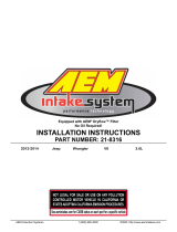
UEGO Sensor
An M18x1.5 oxygen sensor boss needs to be welded into the
exhaust system for installation. This sensor should be
mounted in the exhaust collector where it will sample from
both engine cylinders. On turbocharged engines the UEGO
sensor must be installed after the turbocharger, if not, the
pressure differential will greatly affect the accuracy of the
sensor. To prevent collection of liquids between the sensor
housing and sensor element during the cold start phase, the
installation angle should be inclined at least 10° from horizontal with the electrical connection upwards, see
diagram
MAP Sensor
Two adapters are included with the 3.5bar MAP sensor- a
3/16" hose barb and a -4 AN male fitting. The desired fitting
should be installed to the MAP sensor's 1/8NPT thread with
Teflon thread sealing paste. The MAP sensor should be
securely mounted with a cushioned clamp and plumbed to a
good vacuum source. The vacuum source should pull from a
volume common to both engine cylinders, a manifold vacuum
reference from a single intake runner is not suitable.

INSTALLATION
7
© 2017 AEM Performance Electronics
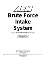
INSTALLATION
1) Remove the driver's side seat (rear seat in "XP
4" four-seater models) to gain access to the
ECU compartment. Remove the access cover.
2) Remove the two screws securing the ECU to
the body panel. Pull the ECU out to gain access
to the connectors. Unlatch the connectors and
remove the ECU from the vehicle. *NOTE these
photos show a RZR XP1000 which has two ECU
connectors, the XP900 has only one ECU
connector.

P/N 30-38088
© 2017 AEM Performance Electronics
3) Connect the two ECU connectors to the AEM
adapter harness inside the ECU compartment.
Route the UEGO sensor connector through the
hole, along the path of the OEM wire harness.
The sensor will need to be installed in an
M18x1.5 threaded bung (AEM p/n 30-4008, sold
separately). This bung is normally included in
the downpipe of an aftermarket turbo kit, but
may be welded into the stock exhaust pipe in a
naturally aspirated application. Mark and trim the
plastic access cover to the pass the AEM
harness through the bottom.
4) Replace the plastic access cover and route
the AEM harness down towards the fuse box,
below the seat bracket. Secure the harness to
the plastic body panel using the supplied
cushion clamp and #8 x 5/8" self-tapping screw.

INSTALLATION
9
© 2017 AEM Performance Electronics
5) Find the storage bin located below the seat.
Place the AEM Infinity ECU against the front
wall of the compartment (opposite the fuse box)
and secure in place with four of the supplied #8 x
5/8" self-tapping screws. Note the orientation of
the ECU in the photo- the large blue connector
should be toward the bottom of the
compartment, with the two USB connectors near
the top.
6) Mount the AEM 3-Channel Coil Driver to the
driver's side of the same compartment with the
two supplied (longer) #8 x 3/4" self-taping
screws.

P/N 30-380810
© 2017 AEM Performance Electronics
7) Install the barbed hose fitting to the AEM
3.5bar MAP sensor. Use Teflon tape or thread
sealing paste on the threads. Mount the MAP
sensor to the plastic panel adjacent to the fuse
box using the supplied cushion clamp and #8 x
5/8" self-tapping screw. Connect the 3/16"
vacuum hose on to the barb fitting and secure
with a zip tie. NOTE: The second sensor shown
in this picture is part of an unrelated boost gauge
install, and was tee'd into the MAP sensor's
vacuum line. This second sensor is not part of
the AEM Infinity installation.
8) Route the vacuum hose around the fuse box
and under the seat mounting bracket. Ensure
the hose is not able to be pinched when the seat
is reinstalled. Pass the hose through the hole in
the plastic body panel located beneath the seat
bracket. The hose will come out on the outside
of the body, adjacent to the OEM voltage
regulator. Route the vacuum hose along the wire
harness up the clutch cover towards the intake
manifold. Secure with supplied zip ties.

INSTALLATION
11
© 2017 AEM Performance Electronics
9) It is important to connect the vacuum hose to
a manifold pressure source located in a plenum
that reference BOTH cylinders. A vacuum/boost
nipple on a single intake runner after the throttle
blade is NOT suitable. This is often located on a
custom fabricated plenum included with an
aftermarket turbo kit. For naturally aspirated
engines, it is acceptable to either leave the
sensor open to atmosphere for a barometric
pressure reference or install a nipple on the
intake tract (after the air filter element) for an
airbox pressure reference.
10) Connect the ring terminal of the fused power
lead on the AEM Infinity harness to the positive
terminal of the battery. Route the ring terminal
through the neck of the terminal boot or trim the
boot as necessary to ensure it can be placed
back in position and protect the positive terminal
from shorting to ground.

P/N 30-380812
© 2017 AEM Performance Electronics
11) Plug in the harness connectors to the MAP
sensor, UEGO sensor, coil driver, and ECU.
Refer to the images in the previous section to
identify the connectors. The wire-exit end of the
Infinity ECU 80-way connector should face
toward the outside of the vehicle.
PINOUTS
Infinity 508 Powersports, P/N 30-7112
Infinity
Pin
Hardware
Reference
Polaris RZR XP
Function
Polaris RZR XP
Pin Destination
Hardware Specification
Notes
C1-1
LowsideSwitch_4
AWD Hub
Control
C2-246
Lowside switch, 1.7A max, NO
internal flyback diode. 12v pullup.
Configured in Base Session for AWD Hub control. Not
user adjustable.
C1-2
LowsideSwitch_5
Spare Lowside
Output
C2-140
Lowside switch, 6A max with internal
flyback diode. Inductive load should
NOT have full time power. 12v
pullup.
May be assigned in Setup Wizard Output Function
Assignments.
C1-3
Injector 7
---
---
For use with high impedance (10-
15ohms) injectors only, 1.7A max.
Available.
C1-4
Injector 8
---
---
For use with high impedance (10-
15ohms) injectors only, 1.7A max.
Available.
C1-5
UEGO 1 Heat
UEGO 1 Heat
C5-4
Bosch UEGO controller
Terminated at 6-pin “Lambda” connector for connecting a
UEGO wideband Bosch LSU4.2 sensor (AEM 30-2001).
C1-6
UEGO 1 IA
UEGO 1 IA
C5-2
C1-7
UEGO 1 IP
UEGO 1 IP
C5-6
C1-8
UEGO 1 UN
UEGO 1 UN
C5-1
C1-9
UEGO 1 VM
UEGO 1 VM
C5-5
C1-10
Batt Perm Power
Permanent
Power
Flying Lead
Dedicated power management CPU
Full time battery power. MUST be powered before the
ignition switch input is triggered.
C1-11
Coil 4
---
---
25 mA max source current
Not used.
C1-12
Coil 3
---
---
25 mA max source current
Not used.
C1-13
Coil 2
Coil 2
C4-5
25 mA max source current
0-5V Falling edge fire. DO NOT connect directly to
coil primary. Connects to included AEM 3-Channel
Ignitior.
C1-14
Coil 1
Coil 1
C4-7
25 mA max source current
0-5V Falling edge fire. DO NOT connect directly to
coil primary. Connects to included AEM 3-Channel
Ignitior.
C1-15
Coil 6
---
---
25 mA max source current
Not used
C1-16
Coil 5
---
---
25 mA max source current
Not used
C1-17
Crank Position
Sensor VR+
Crank
Position
Sensor VR+
C2-239
Differential Variable Reluctance
Zero Cross Detection
See Setup Wizard page 'Cam/Crank' for options.

PINOUTS
13
© 2017 AEM Performance Electronics
C1-18
Crank Position
Sensor VR-
Crank
Position
Sensor VR-
C2-227
C1-19
Cam Position
Sensor 1 VR-
---
---
Differential Variable Reluctance
Zero Cross Detection
Not used.
C1-20
Cam Position
Sensor 1 VR+
---
---
C1-21
LowsideSwitch_2
Cooling Fan
Relay
C2-204
Lowside switch, 1.7A max, NO
internal flyback diode. No pullup.
May be adjusted under Coolant Fan 1 options in Setup
Wizard.
C1-22
LowsideSwitch_3
SYNC Signal
C1-26
Lowside switch, 6A max with internal
flyback diode. Inductive load should
NOT have full time power. No
pullup.
ECU-generated SYNC signal. See "Sequential" section
of Setup Wizard for details.
C1-23
AGND
Sensor
Ground
C3-A, C2-230
Dedicated analog ground
Sensor ground for 0-5v analog inputs.
C1-24
AGND
Sensor
Ground
C2-242, C7-11
Dedicated analog ground
Sensor ground for 0-5v analog inputs.
C1-25
Crank Position
Sensor 1 Hall
---
---
10K pullup to 12V. Will work with
ground or floating switches.
Frequency input only.
Not used.
C1-26
Cam Position
Sensor 1 Hall
SYNC Input
C1-22
10K pullup to 12V. Will work with
ground or floating switches.
Frequency input only.
See Setup Wizard Cam/Crank page for options.
C1-27
Digital_In_2
AWD Request
Signal
C2-228
10K pullup to 12V. Will work with
ground or floating switches.
Frequency input only.
Configured in Base Session for AWD Request Signal.
Not user adjustable.
C1-28
Digital_In_3
Spare
Frequency
Input
C7-4
10K pullup to 12V. Will work with
ground or floating switches.
Frequency input only.
Available frequency input. Can be used for Flex Fuel,
Turbo Speed, or other. See Setup Wizard to configure
input.
C1-29
Digital_In_4
Vehicle Speed
Input
C2-245
10K pullup to 12V. Will work with
ground or floating switches.
Frequency input only.
Configured in Base Session for vehicle speed.May be
adjusted under Vehicle Speed Input options in Setup
Wizard.
C1-30
Digital_In_5
Spare Switch
Input
C7-5
10K pullup to 12V. Will work with
ground or floating switches. Switch
input only.
Available switched input. See Setup Wizard to configure
input.
C1-31
Coil 7
---
---
25 mA max source current
Not used.
C1-32
Coil 8
---
---
25 mA max source current
Not used.
C1-33
Power Ground
Ground
---
Power ground
Power ground.
C1-34
CAN A-
AEMNet CAN-
---
Dedicated high speed CAN
transceiver
Four pin DTM connector in AEM adapter harness.
Contact AEM for additional information.
C1-35
CAN A+
AEMNet
CAN+
---
Dedicated high speed CAN
transceiver
Four pin DTM connector in AEM adapter harness.
Contact AEM for additional information.
C1-36
CAN B-
Chassis
CAN-
C2-248
Dedicated high speed CAN
transceiver
Configured for OEM dash display. Not user adjustable.
C1-37
CAN B+
Chassis
CAN+
C2-236
Dedicated high speed CAN
transceiver
Configured for OEM dash display. Not user adjustable.
C1-38
Temp 1
Coolant Temp
Sensor
C2-244
2.49k pullup to 5v
See Setup Wizard Coolant Temperature page for options.
C1-39
Temp 2
Air Temp
Sensor
C2-224
2.49k pullup to 5v
See Setup Wizard Air Temperature page for options.
C1-40
Temp 3
Spare Temp
Input
C7-6
2.49k pullup to 5v
Available temperature input. Can be used for Oil
Temperature input or other. See Setup Wizard Input
Function Assignments.
C1-41
LowsideSwitch_0
Fuel Pump
C2-219
Lowside switch, 4A max, NO internal
flyback diode. No pullup.
Switched ground. Will prime for 2 seconds at key on
and activate if RPM > 0.
C1-42
LowsideSwitch_1
Spare Lowside
Output
C7-1
Lowside switch, 4A max with internal
flyback diode. Inductive load should
NOT have full time power. No
pullup.
Base session configured to drive boost control solenoid.
May be reassigned in Setup Wizard Output Function
Assignments.
C1-43
Power Ground
Ground
C2-251
Power ground
Power ground.

P/N 30-380814
© 2017 AEM Performance Electronics
C1-44
Knock Sensor 1
---
---
Dedicated knock signal processor
Available. See Setup Wizard Knock Setup page for
options.
C1-45
Knock Sensor 2
---
---
Dedicated knock signal processor
Available. See Setup Wizard Knock Setup page for
options.
C1-46
Power Ground
Ground
C2-252, C7-12
Power ground
Power ground.
C1-47
Main Relay
Control
Ground out to
main relay
C2-202
0.7A max ground sink for external
relay control
Will activate at key on and at key off according to the
configuration settings.
C1-48
Ign Switch
Ignition Switch
C2-209
10k pulldown
Full time battery power must be available at C1-10
before this input is triggered.
C1-49
+5V_Out
+5V Sensor
Power
C2-207, C8-4
Regulated, fused +5V supply for
sensor power
Analog sensor power.
C1-50
+5V_Out
+5V Sensor
Power
C3-B, C7-9
Regulated, fused +5V supply for
sensor power
Analog sensor power.
C1-51
Analog_In_7
Throttle
Position
C2-210
12 bit A/D, 100K pullup to 5V
Configured for TPS input from OEM throttle body.
C1-52
Analog_In_8
MAP
Sensor
C3-C
12 bit A/D, 100K pullup to 5V
See Setup Wizard Basic Sensors page for options.
C1-53
Analog_In_9
Spare Analog
Input
C7-7
12 bit A/D, 100K pullup to 5V
Typically used for fuel pressure. See Input Function
Assignments in Setup Wizard.
C1-54
VR+_In_2
---
---
Differential Variable Reluctance
Zero Cross Detection
Not used.
C1-55
VR-_In_2
---
---
C1-56
VR-_In_3
---
---
Differential Variable Reluctance
Zero Cross Detection
Not used.
C1-57
VR+_In_3
---
---
C1-58
HighsideSwitch_0
---
---
2.6A max, High Side Solid State
Relay
Not used.
C1-59
Stepper_1B
IACV Pin 6
C2-238
Automotive, Programmable Stepper
Driver, up to 28V and ±1.4A
Dedicated stepper idle valve control.
C1-60
Stepper_2B
IACV Pin 3
C2-225
Automotive, Programmable Stepper
Driver, up to 28V and ±1.4A
Dedicated stepper idle valve control.
C1-61
DBW1 Motor-
---
---
5.0A max Throttle Control Hbridge
Drive
Not used.
C1-62
DBW1 Motor+
---
---
5.0A max Throttle Control Hbridge
Drive
Not used.
C1-63
+12v
+12v
C2-253, C5-3,
C7-10
12v power from main relay
12v power from main relay.
C1-64
Injector 6
---
---
For use with high impedance (10-
15ohms) injectors only, 1.7A max.
Not used.
C1-65
Injector 5
---
---
For use with high impedance (10-
15ohms) injectors only, 1.7A max.
Not used.
C1-66
Injector 4
---
---
For use with high impedance (10-
15ohms) injectors only, 1.7A max.
Not used.
C1-67
Power Ground
---
---
Power ground
Power ground.
C1-68
+12v
---
---
12v power from main relay
12v power from main relay.
C1-69
Analog_In_19
---
---
12 bit A/D, 100K pullup to 5V
Not used.
C1-70
Analog_In_18
---
---
12 bit A/D, 100K pullup to 5V
Not used.
C1-71
Analog_In_16
Throttle
Release Sw
C2-232
12 bit A/D, 100K pullup to 5V
Throttle release switch signal.
C1-72
Flash Enable
Flash Enable
Flash Enable
Connector
10k pulldown
Two pin connector in AEM adapter harness. Use only to
force EMS into flash mode if normal firmware update
procedure does not work.
C1-73
Analog_In_13
Spare Analog
Input
C7-8
12 bit A/D, 100K pullup to 5V
Can be used as Oil Pressure, Mode Switch, 3-Step or
other analog input. See Input Function Assignments in
Setup Wizard.

PINOUTS
15
© 2017 AEM Performance Electronics
C1-74
Analog_In_11
Cam Gen
Signal
C2-222
12 bit A/D, 100K pullup to 5V
Analog input for ECU-generated SYNC signal. See
"Sequential" section of Setup Wizard for details.
C1-75
Analog_In_10
Trans Position
Signal
C2-223
12 bit A/D, 100K pullup to 5V
Configured for OEM transmission position. Not user
adjustable.
C1-76
Injector 3
---
---
For use with high impedance (10-
15ohms) injectors only, 1.7A max.
Not used.
C1-77
Injector 2
Injector 2
C2-215
For use with high impedance (10-
15ohms) injectors only, 1.7A max.
Injector 2.
C1-78
Injector 1
Injector 1
C2-205
For use with high impedance (10-
15ohms) injectors only, 1.7A max.
Injector 1.
C1-79
Stepper_2A
IACV Pin 1
C2-237
Automotive, Programmable Stepper
Driver, up to 28V and ±1.4A
Dedicated stepper idle valve control.
C1-80
Stepper_1A
IACV Pin 4
C2-226
Automotive, Programmable Stepper
Driver, up to 28V and ±1.4A
Dedicated stepper idle valve control.

P/N 30-380816
© 2017 AEM Performance Electronics

PINOUTS
17
© 2017 AEM Performance Electronics
C3
MAP
C4
COIL
Pin
Dest. Pin
Default Pin Function
Pin
Dest. Pin
Default Pin Function
1
C1-52
MAP Signal
1
---
---
2
C1-50
+5V
2
---
---
3
C1-23
Sensor Ground
3
C2-255
Harness Coil 2
4
C2-250
Power Ground
5
C1-13
ECU Coil 2
6
C2-256
Harness Coil 1
7
C1-14
ECU Coil 1
C5
LAMBDA
C6
FLASH
Pin
Dest. Pin
Default Pin Function
Pin
Dest. Pin
Default Pin Function
1
C1-8
UEGO Control
A
C1-10, F1-
1
+12V Perm Power
2
C1-6
B
C1-72
Flash Enable
3
C1-63, C2-
253
+12V
4
C1-5
UEGO Control
5
C1-9
6
C1-7

P/N 30-380818
© 2017 AEM Performance Electronics
C7
AUX
F1
BATTERY (+)
Pin
Dest. Pin
Default Pin Function
Pin
Dest. Pin
Default Pin Function
1
C1-42
Lowside 1
1
C1-10
+12V Perm Power
2
C1-2
Lowside 5
3
C1-25
Digital 0
4
C1-28
Digital 3
5
C1-30
Digital 5
6
C1-40
AnalogTemperature3
7
C1-53
Analog 9
8
C1-73
Analog 13
9
C1-50
+5V Ref
10
C1-63
+12V
11
C1-24
Sensor Ground
12
C1-46
Power Ground
12 MONTH LIMITED WARRANTY
Advanced Engine Management Inc. warrants to the consumer that all AEM High Performance products will be free from defects in
material and w orkmanship for a period of twelve (12) months from date of the original purchase. Products that fail within this 12-month
warranty period will be repaired or replaced at AEM’s option, when determined by AEM that the product failed due to defects in material
or workmanship. This warranty is limited to the repair or replacement of the AEM part. In no event shall this warranty exceed the original
purchase price of the AEM part nor shall AEM be responsible for special, incidental or consequential damages or cost incurred due to the
failure of this product. Warranty claims to AEM must be transportation prepaid and accompanied with dated proof of purchase. This
warranty applies only to the original purchaser of product and is non-transferable. All implied warranties shall be limited in duration to the
said 12-month warranty period. Improper use or installation, accident, abuse, unauthorized repairs or alterations voids this warranty.
AEM disclaims any liability for consequential damages due to breach of any written or implied w arranty on all products manufactured by
AEM. Warranty returns will only be accepted by AEM when accompanied by a valid Return Merchandise Authorization (RMA) number.
Product must be received by AEM within 30 days of the date the RMA is issued.
UEGO oxygen sensors are considered wear items and are not covered under warranty.
Please note that before AEM can issue an RMA for any electronic product, it is first necessary for the installer or end user to contact the
EMS tech line at 1-800-423-0046 to discuss the problem. Most issues can be resolved over the phone. Under no circumstances should
a system be returned or a RMA requested before the above process transpires.
AEM will not be responsible for electronic products that are installed incorrectly, installed in a non-approved application, misused, or
tampered with.
Any AEM electronics product can be returned for repair if it is out of the warranty period. There is a minimum charge of $50.00 for
inspection and diagnosis of AEM electronic parts. Parts used in the repair of AEM electronic components will be extra. AEM will provide
an estimate of repairs and receive w ritten or electronic authorization before repairs are made to the product.
/