Page is loading ...

P/N 30-3822
2016 Polaris RZR XP Turbo
AEM Infinity
Plug and Play Harness
AEM Performance Electronics
AEM Performance Electronics, 2205 126th Street Unit A, Hawthorne, CA 90250
Phone: (310) 484-2322 Fax: (310) 484-0152
http://www.aemelectronics.com
Instruction Part Number: 10-3822
Document Build 7/27/2016
Instruction
Manual
WARNING: This installation is not for the tuning novice! Use this system with EXTREME caution! The AEM
Infinity Programmable EMS allows for total flexibility in engine tuning. Misuse or improper tuning of this
product can destroy your engine! If you are not well versed in engine dynamics and the tuning of engine
management systems DO NOT attempt the installation. Refer the installation to an AEM-trained tuning
shop or call 800-423-0046 for technical assistance.
NOTE: All supplied AEM calibrations, Wizards and other tuning information are offered as potential
starting points only. IT IS THE RESPONSIBILITY OF THE ENGINE TUNER TO ULTIMATELY CONFIRM IF THE
CALIBRATION IS SAFE FOR ITS INTENDED USE. AEM holds no responsibility for any engine damage that
results from the misuse or mistuning of this product!
STOP!
THIS PRODUCT HAS LEGAL RESTRICTIONS.
READ THIS BEFORE INSTALLING/USING!
THIS PRODUCT MAY BE USED SOLELY ON VEHICLES USED IN SANCTIONED COMPETITION WHICH MAY NEVER BE USED UPON A
PUBLIC ROAD OR HIGHWAY, UNLESS PERMITTED BY SPECIFIC REGULATORY EXEMPTION. (VISIT THE “EMISSIONS” PAGE AT HTTP://
WWW.SEMASAN.COM/EMISSIONS FOR STATE BY STATE DETAILS.)
IT IS THE RESPONSIBILITY OF THE INSTALLER AND/OR USER OF THIS PRODUCT TO ENSURE THAT IT IS USED IN COMPLIANCE WITH
ALL APPLICABLE LAWS AND REGULATIONS. IF THIS PRODUCT WAS PURCHASED IN ERROR, DO NOT INSTALL AND/OR USE IT. THE
PURCHASER MUST ARRANGE TO RETURN THE PRODUCT FOR A FULL REFUND.
THIS POLICY ONLY APPLIES TO INSTALLERS AND/OR USERS WHO ARE LOCATED IN THE UNITED STATES; HOWEVER CUSTOMERS
WHO RESIDE IN OTHER COUNTRIES SHOULD ACT IN ACCORDANCE WITH THEIR LOCAL LAWS AND REGULATIONS.

P/N 30-38222
© 2016 AEM Performance Electronics
OVERVIEW
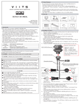
The 30-3822 AEM Infinity PnP Harness was designed to run the 2016 Polaris RZR XP Turbo. This is a true
standalone system that eliminates the use of the stock Polaris ECU. The use of this harness makes the kit “plug
and play” so no cutting or splicing wires is necessary. The base configuration files available for the Infinity EMS are
starting points only and will need to be modified for every specific application.
The appropriate Infinity ECU part number for this adapter kit is:
· 30-7112 INFINITY 508, POWERSPORTS
Please read this document in its entirety before attempting to start or run an engine.
GETTING STARTED
Your Infinity EMS will be packaged with four important documents: Usage Legality Disclaimer, Software Download
Notice, Security Code Notice, and an Infinity Quick Start Guide.
First, read and acknowledge the Usage Legality Disclaimer. Second, refer to the Infinity Quick Start Guide (QSG).
Third, follow the Software Download Notice and download the Infinity Tuner software from the AEM Electronics
web site. Fourth, visit www.aeminfinity.com to register your EMS (See "Account Registration" in QSG). Once the
registration process is complete, you'll be able to download the latest firmware for your EMS*. The final setup
process is to open the Infinity Tuner software and connect to your EMS to update the firmware (See "Firmware
Update" in QSG. This can be done once the EMS is installed into your vehicle - see Installation section.
Once the Infinity is installed into your vehicle and it has been loaded with the latest firmware, setup and tuning may
commence. Refer to the QSG for additional information on getting the engine ready for tuning with the Infinity
EMS. Additionally, the full Infinity User Manual can be referenced for more in-depth information pertaining to the
install, setup, and usage of the Infinity EMS.
*Be sure to download Inf-508 Polaris RZR XP Turbo firmware. Do NOT download the Inf-508 Polaris RZR900/
RZR1000 firmware.

GETTING STARTED
3
© 2016 AEM Performance Electronics
IMPORTANT APPLICATION NOTES
The 30-3822 AEM Infinity PnP Harness allows for a "plug and play" installation of an AEM Infinity 508 Powersports
ECU to a 2016 Polaris RZR Turbo. This kit completely replaces the stock ECU and offers full control of fuel
injection, ignition timing advance, and drive by wire (DBW) electronic throttle control. The Infinity ECU also
supports the factory Polaris dash display functions, as well as the AWD hub control.
Fuel Injectors
The stock RZR Turbo fuel injectors flow 450 cc/min. These injectors have been characterized by AEM and are
available for selection in the Setup Wizard but testing has shown that the stock injectors operate near 100% duty
cycle when ran at the factory rated power/boost level. It's suggested that larger injectors be installed in order to
support higher than stock power/boost levels. The Setup Wizard includes injector data for many popular
aftermarket fuel injectors. Please note that the Infinity 508 Powersports ECU can only drive high impedance
injectors and low impedance or "peak and hold" injectors are not supported.
Ignition Coils
The OEM Polaris two-wire ignition coils are controlled by the AEM Infinity ECU, but they are not driven directly.
This kit includes the AEM 3-Channel Coil Driver required to drive these coils integrated into the PnP harness.
Drive by Wire (DBW) Throttle Control
The base session provided by AEM is configured to work with the stock Polaris electronic throttle body and
accelerator pedal position sensor. When the system is installed for the first time, the Drive By Wire Setup Wizard
should be run with "Calibrate Sensor Data Only" selected to calibrate the Infinity to your specific vehicle's sensors.
Sensors and Speed Density Fueling
The Infinity will run the engine with a speed density fueling control using the stock Polaris Manifold Air Pressure
(MAP), Intake Air Temperature (IAT) and Coolant Temperature (CLT) sensors. The stock MAP sensor reads up to
300kpa. The Infinity also references the stock air box/barometric pressure sensor.
UEGO Wideband Oxygen Sensor and mounting bung
The Infinity includes on board control for one UEGO wideband oxygen sensor. The Bosch LSU 4.2 sensor
(included in this kit) plugs in directly to the AEM Infinity PnP Harness. The included oxygen sensor bung should be
welded into the exhaust system after the turbo but before the catalytic converter (if still equipped). Oxygen sensor
bungs and replacement sensors are available from AEM.
35-4005 O2 Sensor Bung, Mild Steel
35-4008 O2 Sensor Bung, Tall Stainless Steel
30-2001 Bosch LSU 4.2 Wideband UEGO Replacement Sensor

P/N 30-38224
© 2016 AEM Performance Electronics
KIT CONTENTS
AEM P/N
Description
Qty
35-3822
AEM Infinity PnP Harness
1
35-2843
Ignitor, 3-Channel with Thermal Paste
1
35-2001
Bosch LSU 4.2 Wideband UEGO Sensor
1
35-4005
Oxygen sensor bung
1
1-3071
Cushion Clamp, 7/8"
1
1-3069
Screw, Self-Tapping #8 x 5/8"
5
1-3070
Screw, Self-Tapping #8 x 3/4"
2
1062-20-0122
Socket, Aux Connector with terminals
12
10-3822
Instruction Sheet, 30-3822
1
INFINITY CONNECTORS
The AEM Infinity EMS uses the MX123 Sealed Connection System from Molex. AEM strongly recommends that
users become familiar with the proper tools and procedures before attempting any modifications. The entire user
manual can be downloaded direct from Molex at:
http://www.molex.com/mx_upload/family//MX123UserManual.pdf
**NOTE** DUE TO EXPOSURE TO DIRT AND MUD, THE FOLLOWING CLEANING PROCEDURE MUST BE
FOLLOWED IN ORDER TO PREVENT DAMAGE TO THE MAIN WIRING HARNESS CONNECTOR. DO NOT
ATTEMPT TO UNLATCH AND REMOVE THE MAIN CONNECTOR IF IT'S DIRTY PRIOR TO CLEANING!!
DAMAGE TO THE MAIN HARNESS CONNECTOR DUE TO LACK OF OR IMPROPER CLEANING IS NOT
COVERED UNDER WARRANTY!!

INFINITY CONNECTORS
5
© 2016 AEM Performance Electronics
Cleaning Instructions - DO NOT ATTEMPT TO
UNLATCH OR REMOVE THE CONNECTOR UNTIL
STEP 3.
Note dirt and grit built up around latch lock and in connector
slides. All debris must be removed before attempting to
unlatch and remove connector.
1. With the connector still in place and latched, use a
squirt bottle to squirt water liberally and directly onto the
connector slides and around all exposed surfaces to
loosen and remove dirt, grit and small rocks. Repeat as
necessary.
Squirt water liberally to the areas indicated
2. With the connector still in place and latched, use
high pressure air to remove loosened debris. Direct air
stream around connector slides and all exposed
surfaces. Repeat as necessary.

P/N 30-38226
© 2016 AEM Performance Electronics
3. Release latch lock and gently attempt to lift the latch
to determine if there is excessive resistance. If latch
binds or resistance is felt, stop and move to Step 4.
4. If resistance is felt while unlatching the connector,
continue cleaning the connector with the latch raised to
the point of resistance. Cycle the latch back and forth
to help loosen additional debris.
Continue to clean out debris by squirting water into
connector slides

INFINITY CONNECTORS
7
© 2016 AEM Performance Electronics
5. Repeat previous steps until the connector slides are
completely free of dirt and debris and the connector can
be fully unlatched and removed with little resistance.
Clean connector slides
6. Once connector is removed, check the slides for any
debris. Use a clean damp paper towel or rag to remove
debris from the outsides of the connector. Use caution
when wiping near the terminal openings.
Clean outside of connector housing - avoid terminal
openings
8. Use a clean damp paper towel or rag to remove
debris from the outside of the header connector. Use
caution to avoid getting debris into connector.

P/N 30-38228
© 2016 AEM Performance Electronics
INFINITY ADAPTER HARNESS
The core of the AEM Infinity PnP Harness Kit is the main harness that connects between the Polaris engine
harness (replacing the stock ECU) and the AEM Infinity EMS. The harness connections for the various power,
sensors, and auxiliary options are described here.
Connections
Aux - This 12-way connector is used to adapt many
common ancillary inputs and outputs easily. Included in
this kit are a 12-way mating connector, 12 terminals,
and a connector wedgelock. These components will
need to be terminated by the installer with 16-22ga wire.
Note: the pin numbering is molded into the wire side of
the connector. See 'Pinouts' section for details of this
connector's pins.
ECU Header - Plugs into cars stock wiring harness.
Lambda - This 6-way terminated connector plugs
directly into the included wideband oxygen UEGO
sensor, AEM P/N 30-2001. The included M18x1.5
oxygen sensor bung needs to be welded into the
exhaust system for installation. The sensor should be
mounted in the exhaust collector where it will sample
from both engine cylinders. On turbocharged engines
the UEGO sensor must be installed after the
turbocharger, if not, the pressure differential will greatly
affect the accuracy of the sensor. To prevent collection
of liquids between the sensor housing and sensor
element during the cold start phase, the installation
angle should be inclined at least 10° from horizontal with
the electrical connection upwards.

INFINITY ADAPTER HARNESS
9
© 2016 AEM Performance Electronics
Signal - This is a sealed, self-contained signal
conditioner. This plug will come pre-terminated and
should be secured out of the way of hot or moving parts.
Do NOT remove.
Coil - This connector should be plugged into the
included 3-Channel Ignitor as shown.
AEMnet - AEMnet is an open architecture based on
CAN 2.0 which provides the ability for multiple enabled
devices, such as race dashes, data loggers, etc., to
easily commumicate with one another through two
twisted cables (CAN+/CAN-).
Flash - This 2-way connector is used for secondary
hardware flashing. This connector is normally protected
with a dust cap. The included shunt connector jumps
the two wires together when required. Once initially
flashed, the EMS is normally upgraded in the software,
not requiring this connector.
Battery (+) - The red flying lead ring terminal should be
connected to the battery positive terminal. This provides
permanent power to the ECU. The fuse holder contains
a 5A fuse. Always replace with a fuse of the same
rating.
ECU C1 - Plugs into Infinity EMS.

P/N 30-382210
© 2016 AEM Performance Electronics
INSTALLATION
1. Remove the driver's side seat (rear seat in "XP 4" four-
seater models) to gain access to the ECU compartment.
Remove the access cover.
2. Remove the two screws securing the ECU to the body
panel. Pull the ECU out to gain access to the
connectors. Unlatch the connectors and remove the ECU
from the vehicle.
3. Connect the two ECU connectors to the AEM adapter
harness inside the ECU compartment. Route the UEGO
sensor connector through the hole to the UEGO sensor
location. Mark and trim the plastic access cover to the
pass the AEM harness through the bottom.

INSTALLATION
11
© 2016 AEM Performance Electronics
4. Replace the plastic access cover and route the AEM
harness down towards the fuse box, below the seat
bracket. Secure the harness to the plastic body panel
using the supplied cushion clamp and #8 x 5/8" self-
tapping screw.
5. Find the storage bin located below the seat. Place the
AEM Infinity ECU against the front wall of the
compartment (opposite the fuse box) and secure in place
with four of the supplied #8 x 5/8" self-tapping screws.
Note the orientation of the ECU in the photo- the large
blue connector should be toward the bottom of the
compartment, with the two USB connectors near the
top.
6. Mount the AEM 3-Channel Coil Driver to the driver's
side of the same compartment with the two supplied
(longer) #8 x 3/4" self-taping screws.

P/N 30-382212
© 2016 AEM Performance Electronics
7. Connect the ring terminal of the fused power lead on
the AEM Infinity harness to the positive terminal of the
battery. Route the ring terminal through the neck of the
terminal boot or trim the boot as necessary to ensure it
can be placed back in position and protect the positive
terminal from shorting to ground.
8. Plug in the harness connectors to the UEGO sensor,
coil driver, and ECU. Refer to the images in the previous
section to identify the connectors. The wire-exit end of
the Infinity ECU 80-way connector should face toward the
outside of the vehicle.
9. Installation complete. Refer to Getting Started for
information on loading Infinity with firmware.

INSTALLATION
13
© 2016 AEM Performance Electronics
PINOUTS
Infinity-508 Powersports, PN 30-7112
Infinity
Pin
Hardware
Reference
RZR
Function
RZR
Pin Destination
Hardware Specification
Notes
C1-1
Lowside 4
AWD Hub
Control
C2-246
Lowside switch, 1.7A max, NO internal
flyback diode. 12v pullup.
Hard coded for AWD Hub Control. Not user
configurable.
C1-2
Lowside 5
Chassis Relay
Control
C2-140
Lowside switch, 6A max with internal
flyback diode. Inductive load should
NOT have full time power. 12v pullup.
Hard coded for Chassis Relay Control. Not user
configurable.
C1-3
Injector 7
For use with high impedance (10-
15ohms) injectors only, 1.7A max.
Not used.
C1-4
Injector 8
For use with high impedance (10-
15ohms) injectors only, 1.7A max.
Not used.
C1-5
UEGO 1 Heat
UEGO 1 Heat
C5-4
Bosch UEGO controller
"Lambda" harness branch connects to Bosch UEGO
LSU 4.2 sensor (AEM pn 30-2001) .
C1-6
UEGO 1 IA
UEGO 1 IA
C5-2
C1-7
UEGO 1 IP
UEGO 1 IP
C5-6
C1-8
UEGO 1 UN
UEGO 1 UN
C5-1
C1-9
UEGO 1 VM
UEGO 1 VM
C5-5
C1-10
Batt Perm
Power
Permanent
Power
Battery Lead
Dedicated power management CPU
Full time battery power. MUST be powered before the
ignition switch input is triggered.
C1-11
Coil 4
25 mA max source current
Not used.
C1-12
Coil 3
25 mA max source current
Not used
C1-13
Coil 2
Coil 2
C3-5
25 mA max source current
0-5v falling edge ignition trigger. DO NOT connect
directly to coil primary. Connects to included AEM 3
Channel Ignitor.
C1-14
Coil 1
Coil 1
C3-7
25 mA max source current
0-5v falling edge ignition trigger. DO NOT connect
directly to coil primary. Connects to included AEM 3
Channel Ignitor.
C1-15
Coil 6
Not used.
C1-16
Coil 5
Not used.
C1-17
Crank Position
Sensor VR+
Crank Position
Sensor VR+
C2-213
Differential Variable Reluctance Zero
Cross Detection
VR crank input.
C1-18
Crank Position
Sensor VR-
Crank Position
Sensor VR-
C2-201
C1-19
Cam Position
Sensor 1 VR-
Differential Variable Reluctance Zero
Cross Detection
Not used.
C1-20
Cam Position
Sensor 1 VR+
C1-21
Lowside 2
Coolant Fan
C2-141
Lowside switch, 1.7A max, NO internal
flyback diode. No pullup.
Configured in RZR base session for Coolant Fan.
C1-22
Lowside 3
Spare Lowside
Output
C6-1
Lowside switch, 6A max with internal
flyback diode. Inductive load should
NOT have full time power. No pullup.
Available lowside output in Aux connector. See Setup
Wizard to configure.
C1-23
AGND
Sensor Ground
C2-103, C2-104,
C2-105, C2-106
Dedicated analog ground
Sensor ground for 0-5v analog inputs.
C1-24
AGND
Sensor Ground
C2-204, C2-208,
C2-237, C6-11
Dedicated analog ground
Sensor ground for 0-5v analog inputs.
C1-25
Crank Position
Sensor 1 Hall
10K pullup to 12V. Will work with
ground or floating switches. Frequency
input only.
Not used.
C1-26
Cam Position
Sensor 1 Hall
10K pullup to 12V. Will work with
ground or floating switches. Frequency
input only.
Not used.
C1-27
Digital 2
AWD Request
Signal
C2-120
10K pullup to 12V. Will work with
ground or floating switches. Frequency
input only.
Hard coded for AWD Request. Not user configurable.
C1-28
Digital 3
Spare Frequency
Input
C6-3
10K pullup to 12V. Will work with
ground or floating switches. Frequency
input only.
Spare frequency input in Aux connector. Can be used
for Flex Fuel or Turbo Speed or other frequency input.
See Setup Wizard to configure input.
C1-29
Digital 4
Vehicle Speed
Sensor
C2-232
10K pullup to 12V. Will work with
ground or floating switches. Frequency
input only.
Configured in RZR base session for Vehicle Speed.

P/N 30-382214
© 2016 AEM Performance Electronics
C1-30
Digital 5
Brake Switch
C2-135
No pullup. Works with 12v switch
inputs. Switch input only.
Configured in RZR base sessin for Brake Switch.
C1-31
Coil 7
25 mA max source current
Not used.
C1-32
Coil 8
25 mA max source current
Not used.
C1-33
Power Ground
Ground
C2-247
Power ground
Power ground.
C1-34
CAN A-
AEMnet CAN-
C8-2
Dedicated high speed CAN transceiver
AEMnet.
C1-35
CAN A+
AEMnet CAN+
C8-1
Dedicated high speed CAN transceiver
AEMnet.
C1-36
CAN B-
Chassis CAN-
C2-144
Dedicated high speed CAN transceiver
Hard coded for stock dash display.
C1-37
CAN B+
Chassis CAN+
C2-132
Dedicated high speed CAN transceiver
Hard coded for stock dash display.
C1-38
Temp 1
Coolant Temp
Sensor
C2-215
2.49k pullup to 5v
RZR coolant temp sensor.
C1-39
Temp 2
Air Temp
Sensor
C2-227
2.49k pullup to 5v
RZR air temp sensor.
C1-40
Temp 3
Spare Temp
Input
C6-6
2.49k pullup to 5v
Spare temp input in Aux connector. Can be used for Oil
Temperature input. See Setup Wizard Oil Temperature
page.
C1-41
Lowside 0
Fuel Pump
Relay
C2-142
Lowside switch, 4A max, NO internal
flyback diode. No pullup.
Switched ground. Will prime at key on and activate
when RPM>0.
C1-42
Lowside 1
Boost Control
C2-101
Lowside switch, 4A max with internal
flyback diode. Inductive load should
NOT have full time power. No pullup.
Configured in RZR base session for boost control.
See Setup Wizard Boost Control page for options.
Monitor BoostControl [%] channel for output state.
C1-43
Power Ground
Ground
C2-154
Power ground
Power ground.
C1-44
Knock Sensor 1
Knock Sensor 1
C2-238
Dedicated knock signal processor
RZR knock sensor.
C1-45
Knock Sensor 2
Dedicated knock signal processor
Not used.
C1-46
Power Ground
Ground
C2-153
Power ground
Power ground.
C1-47
Main Relay
Control
Ground out to
main relay
C2-115
0.7A max ground sink for external relay
control
Will activate at key on and at key off according to the
configuration settings.
C1-48
Ign Switch
Ignition Switch
C2-116
10k pulldown
Full time battery power must be available at C1-10
before this input is triggered.
C1-49
5v Sensor
Power
+5V Sensor
Power
C2-125, C2-137,
C2-138
Regulated, fused +5V supply for sensor
power
Analog sensor power.
C1-50
5v Sensor
Power
+5V Sensor
Power
C2-210, C2-223
Regulated, fused +5V supply for sensor
power
Analog sensor power.
C1-51
Analog 7
DBW TPS1
C2-203
12 bit A/D, 100K pullup to 5V
TPS1 input from DBW throttle body.
C1-52
Analog 8
MAP
Sensor
C2-219
12 bit A/D, 100K pullup to 5V
RZR MAP sensor.
C1-53
Analog 9
Fuel Sender
Signal
C2-112
12 bit A/D, 100K pullup to 5V
Hard coded for fuel level input. Not user configurable.
C1-54
VR+ 2
Differential Variable Reluctance Zero
Cross Detection
Not used.
C1-55
VR- 2
C1-56
VR- 3
Differential Variable Reluctance Zero
Cross Detection
Not used.
C1-57
VR+ 3
C1-58
Highside 0
Brake Lights
C2-113, C2-150
2.6A max, High Side Solid State Relay
Brake light control.
C1-59
Stepper 1B
Automotive, Programmable Stepper
Driver, up to 28V and ±1.4A
Not used.
C1-60
Stepper 2B
Automotive, Programmable Stepper
Driver, up to 28V and ±1.4A
Not used.
C1-61
DBW Motor-
DBW Throttle
Close
C2-252
5.0A max Throttle Control Hbridge Drive
DBW throttle control. Base session is configured for
stock DBW TB. Other TB's may be used but will
require setup and characterization. See Drive By Wire
Wizard.
C1-62
DBW Motor+
DBW Throttle
Open
C2-251
5.0A max Throttle Control Hbridge Drive
DBW throttle control. Base session is configured for
stock DBW TB. Other TB's may be used but will
require setup and characterization. See Drive By Wire
Wizard.
C1-63
+12v
+12v
C2-155
12v power from main relay
12v power from main relay.
C1-64
Injector 6
For use with high impedance (10-
15ohms) injectors only, 1.7A max.
Not used.
C1-65
Injector 5
For use with high impedance (10-
15ohms) injectors only, 1.7A max.
Not used.
C1-66
Injector 4
For use with high impedance (10-
15ohms) injectors only, 1.7A max.
Not used.
C1-67
Power Ground
Power ground
C1-68
+12v
+12v
C2-156
12v power from main relay
12v power from main relay.

PINOUTS
15
© 2016 AEM Performance Electronics
C1-69
Analog 19
DBW APP2
C2-111
12 bit A/D, 100K pullup to 5V
Accelerator Pedal Position Sensor 2.
C1-70
Analog 18
DBW APP1
C2-121
12 bit A/D, 100K pullup to 5V
Accelerator Pedal Position Sensor 1.
C1-71
Analog 16
DBW TPS2
C2-220
12 bit A/D, 100K pullup to 5V
TPS2 input from DBW throttle body.
C1-72
Flash Enable
Flash
10k pulldown
Two pin connector in AEM adapter harness. Use only
to force EMS into flash mode if normal firmware update
procedure does not work.
C1-73
Analog 13
Available Analog
Input
C6-4
12 bit A/D, 100K pullup to 5V
Spare Analog Input in Aux connector. Can be used as
Oil Pressure, Mode Switch, 3-Step or other analog input.
See Oil Pressure or Input Function Assignments in
Setup Wizard.
C1-74
Analog 11
Trans Position
Signal
C2-123
12 bit A/D, 100K pullup to 5V
Hard coded for tranmission position input. Not user
configurable.
C1-75
Analog 10
Baro/Air Box
Pressure
C2-110
12 bit A/D, 100K pullup to 5V
RZR barometric/air box pressure sensor.
C1-76
Injector 3
For use with high impedance (10-
15ohms) injectors only, 1.7A max.
Not used.
C1-77
Injector 2
Injector 2
C2-243
For use with high impedance (10-
15ohms) injectors only, 1.7A max.
Injector 2.
C1-78
Injector 1
Injector 1
C2-244
For use with high impedance (10-
15ohms) injectors only, 1.7A max.
Injector 1.
C1-79
Stepper 2A
Automotive, Programmable Stepper
Driver, up to 28V and ±1.4A
Not used.
C1-80
Stepper 1A
Automotive, Programmable Stepper
Driver, up to 28V and ±1.4A
Not used.

P/N 30-382216
© 2016 AEM Performance Electronics
C3
IGNITOR
C4
LAMBDA
Pin
Dest. Pin
Default Pin Function
Pin
Dest. Pin
Default Pin Function
1
1
C1-8
UEGO UN
2
2
C1-6
UEGO IA
3
C2-254
Harness Coil 2
3
+12V
Switched Power
4
C2-250
Power Ground
4
C1-5
UEGO Heat
5
C1-13
ECU Coil 2
5
C1-9
UEGO VM
6
C2-256
Harness Coil 1
6
C1-7
UEGO IP
7
C1-14
ECU Coil 1
C5
FLASH
C6
AUX
Pin
Dest. Pin
Default Pin Function
Pin
Dest. Pin
Default Pin Function
1
C1-10, F1-
1
+12V Perm Power
1
C1-22
Lowside 3
2
C1-72
Flash Enable
2
3
C1-28
Digital 3
4
C1-73
Analog 13
5
6
C1-40
Temp 3
7
8
9
5v
5v
10
12v
12v
11
SGND
Sensor Ground
12
GND
Ground

PINOUTS
17
© 2016 AEM Performance Electronics
12 MONTH LIMITED WARRANTY
Advanced Engine Management Inc. warrants to the consumer that all AEM High Performance products will be free from defects in
material and workmanship for a period of twelve (12) months from date of the original purchase. Products that fail within this 12-month
warranty period will be repaired or replaced at AEM’s option, when determined by AEM that the product failed due to defects in material
or workmanship. This warranty is limited to the repair or replacement of the AEM part. In no event shall this warranty exceed the original
purchase price of the AEM part nor shall AEM be responsible for special, incidental or consequential damages or cost incurred due to the
failure of this product. Warranty claims to AEM must be transportation prepaid and accompanied with dated proof of purchase. This
warranty applies only to the original purchaser of product and is non-transferable. All implied warranties shall be limited in duration to the
said 12-month w arranty period. Improper use or installation, accident, abuse, unauthorized repairs or alterations voids this warranty.
AEM disclaims any liability for consequential damages due to breach of any written or implied warranty on all products manufactured by
AEM. Warranty returns will only be accepted by AEM when accompanied by a valid Return Merchandise Authorization (RMA) number.
Product must be received by AEM w ithin 30 days of the date the RMA is issued.
UEGO oxygen sensors are considered wear items and are not covered under warranty.
Please note that before AEM can issue an RMA for any electronic product, it is first necessary for the installer or end user to contact the
EMS tech line at 1-800-423-0046 to discuss the problem. Most issues can be resolved over the phone. Under no circumstances should
a system be returned or a RMA requested before the above process transpires.
AEM will not be responsible for electronic products that are installed incorrectly, installed in a non-approved application, misused, or
tampered with.
Any AEM electronics product can be returned for repair if it is out of the warranty period. There is a minimum charge of $50.00 for
inspection and diagnosis of AEM electronic parts. Parts used in the repair of AEM electronic components will be extra. AEM will provide
an estimate of repairs and receive written or electronic authorization before repairs are made to the product.
/