Page is loading ...

P/N 30-3515
1989-1998 Nissan Skyline GT-R
RB26DETT
AEM Infinity PnP Harness
AEM Performance Electronics
AEM Performance Electronics, 2205 126th Street Unit A, Hawthorne, CA 90250
Phone: (310) 484-2322 Fax: (310) 484-0152
http://www.aemelectronics.com
Instruction Part Number: 10-3515
Document Build 2017-09-29
Instruction
Manual
WARNING: This installation is not for the tuning novice! Use this system with EXTREME caution! The AEM
Infinity Programmable EMS allows for total flexibility in engine tuning. Misuse or improper tuning of this
product can destroy your engine! If you are not well versed in engine dynamics and the tuning of engine
management systems DO NOT attempt the installation. Refer the installation to an AEM-trained tuning
shop or call 800-423-0046 for technical assistance.
NOTE: All supplied AEM calibrations, Wizards and other tuning information are offered as potential
starting points only. IT IS THE RESPONSIBILITY OF THE ENGINE TUNER TO ULTIMATELY CONFIRM IF THE
CALIBRATION IS SAFE FOR ITS INTENDED USE. AEM holds no responsibility for any engine damage that
results from the misuse or mistuning of this product!
STOP!
THIS PRODUCT HAS LEGAL RESTRICTIONS.
READ THIS BEFORE INSTALLING/USING!
THIS PRODUCT MAY BE USED SOLELY ON VEHICLES USED IN SANCTIONED COMPETITION WHICH MAY NEVER BE USED UPON A
PUBLIC ROAD OR HIGHWAY, UNLESS PERMITTED BY SPECIFIC REGULATORY EXEMPTION. (VISIT THE “EMISSIONS” PAGE AT
HTTP://WWW.SEMASAN.COM/EMISSIONS FOR STATE BY STATE DETAILS.)
IT IS THE RESPONSIBILITY OF THE INSTALLER AND/OR USER OF THIS PRODUCT TO ENSURE THAT IT IS USED IN COMPLIANCE WITH
ALL APPLICABLE LAWS AND REGULATIONS. IF THIS PRODUCT WAS PURCHASED IN ERROR, DO NOT INSTALL AND/OR USE IT. THE
PURCHASER MUST ARRANGE TO RETURN THE PRODUCT FOR A FULL REFUND.
THIS POLICY ONLY APPLIES TO INSTALLERS AND/OR USERS WHO ARE LOCATED IN THE UNITED STATES; HOWEVER CUSTOMERS
WHO RESIDE IN OTHER COUNTRIES SHOULD ACT IN ACCORDANCE WITH THEIR LOCAL LAWS AND REGULATIONS.

P/N 30-35152
© 2017 AEM Performance Electronics
OVERVIEW
The 30-3515 AEM Infinity PnP Harness Adapter was designed to run 1989-1998 Nissan Skyline GT-R with
RB26DETT engines. This is a true standalone system that eliminates the use of the Nissan ECU and mass airflow
sensors. The Infinity ECU supports the factory CAS (Cam Angle Sensor), so replacing the disk within the CAS is
not required. The use of this harness makes the kit “plug and play” so no cutting or splicing wires is necessary
(when used with optional 30-3510-00 AUX harness, sold separately). The base configuration files available for the
Infinity EMS are starting points only and will need to be modified for every specific application.
The available Infinity EMS part numbers for this adapter kit are:
· 30-7106 INFINITY 506
· 30-7108 INFINITY 508* (*Use of this ECU will result in the loss of certain functions- VTC Solenoid and MIL.
Refer to Pinout below for details.)
Please read this document in its entirety before attempting to start or run an engine.
GETTING STARTED
Refer to the 10-7100 for EMS 30-7100 Infinity Quick Start Guide for additional information on getting
the engine started with the Infinity EMS. The base session is located in C:\Documents\AEM\Infinity
Tuner\Sessions\Base Sessions.
DOWNLOADABLE FILES
Files can be downloaded from www.aeminfinity.com. An experienced tuner must be available to configure
and manipulate the data before driving can commence. The Quick Start Guide and Full Manual describe
the steps for logging in and registering at www.aeminfinity.com. These documents are available for
download here: http://www.aemelectronics.com/products/support

DOWNLOADABLE FILES
3
© 2017 AEM Performance Electronics
Kit Contents
Diagram
AEM P/N
Description
Qty
A
36-3515
AEM Infinity Skyline GT-R PnP Harness
1
B
8-500
Velcro, Hook Side
12"
C
8-500
Velcro, Loop Side
12"
D
4-1008
12-Way Aux Connector, Sealed
1
E
4-1009
Dust Cap, Flash Enable
1
F
4-1010
Jumper, Flash Enable
1
G
1062-20-0122
Socket, Aux Connector
12
10-3515
Instruction Sheet, 30-3515
1

P/N 30-35154
© 2017 AEM Performance Electronics
Important Application Notes
The 30-3515 AEM Infinity PnP Harness allows for a "plug and play" installation of either an AEM Infinity 506 or
Infinity 508* ECU to a 1989-1998 Nissan Skyline equipped with one of the following engines:
1989-1998 RB26DETT 2.6L DOHC I-6, Twin Turbo
1989-1994 RB20DET 2.0L DOHC I-6, Single Turbo
1993-1998 RB25DET 2.5L DOHC I-6, Single Turbo
*Use of the Infinity-8h ECU will result in the loss of certain functions- VTC Solenoid and MIL. Refer to Pinout below
for details.
The AEM Infinity ECU will run the engine with a speed density fueling calculation, eliminating the need for an OEM
airbox and mass airflow sensor (MAF). Required are an intake air temperature (IAT) sensor and manifold absolute
pressure (MAP) sensor. AEM also offers an auxiliary sub-harness to make adding these sensors a plug and play
installation.
30-2010 Air Temp Sensor Kit, 3/8" NPT
30-2130-50 3.5bar (50PSIa) Stainless Steel MAP Sensor Kit
30-3510-00 Auxiliary Harness for AEM MAP and IAT Sensors
The AEM Infinity ECU includes on board control for one UEGO wideband oxygen sensor. This sensor connects to
the AEM Infinity PnP Harness via a 6-pin DTM-style plug. AEM offers a UEGO extension harness that is 72" long
and will connect the UEGO sensor to the PnP harness.
30-2001 Bosch LSU 4.2 Wideband UEGO Replacement Sensor
30-3600 Infinity O2 Sensor Extension Harness (72")
The AEM Infinity ECU supports the OEM Nissan Cam Angle Sensor (CAS) '360 Degree' pattern. The base session
is pre-configured and will sync close enough for startup with the OEM CAS disk. Previous AEM ECUs may have
required the CAS trigger disk to be replaced with an AEM-supplied disk that has a 12 crank / 1 cam pattern. If the
engine already has one of these AEM disks installed, the Infinity ECU may be reconfigured via the Setup Wizard to
properly read this pattern. In the Cam/Crank section of the Setup Wizard, select sensor type Universal 12 Hall
Crank & 1 Hall Cam. The timing will need to be sync'd with a timing light before attempting to fire the engine.
Refer to the Infinity User Guide for detailed instructions on setting up a universal Cam/Crank pattern.
The AEM Infinity PnP harness includes a dedicated TPS signal output circuit for use with Skyline GT-R auxiliary
devices (ATTESA AWD control and dashboard display). This output signal is located at pin 56 of the Nissan ECU
connector for plug and play operation of these devices. The output signal will directly follow the TPS voltage as it is
calibrated via the Set Throttle Range section of the Setup Wizard.
Many Nissan wiring harnesses have been found to contain significant differences between model years
and/or trim levels. Likely differences include: Crank signal, Cam signal, Ignition switch wiring (the
Ignition switch input controls the Main Relay output), injector and coil destinations. Official
documentation for many of these vehicles was not offered in English, so it would be very wise to double-
check the pinout destinations for these circuits. This is especially true if the vehicle contains a ‘swapped’
engine or if the wiring harness has been cut, spliced, soldered, re-routed, re-pinned or modified in any
other manner. It is the user’s responsibility to check that the wiring on the vehicle matches the pinout
chart contained in this instruction manual.

Important Application Notes
5
© 2017 AEM Performance Electronics
INFINITY ADAPTER HARNESS
The AEM Infinity Plug and Play Harness connects between the OEM Nissan harness and the AEM Infinity ECU,
completely replacing the OEM ECU. The harness connections for the various sensors and auxiliary options are
described here.

P/N 30-35156
© 2017 AEM Performance Electronics
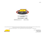
Connections
Lambda - This 6-way DTM-style connector
plugs directly into an optional AEM UEGO
extension harness, AEM P/N 30-3600. The
Bosch LSU 4.2 UEGO Sensor, AEM P/N 30-
2001, will plug into that extension harness.
Refer to 'UEGO Sensor' section for mounting
requirements.
AUX - This 12-way connector is used to
adapt many common ancillary inputs and
outputs easily. Included in this kit are a 12-
way mating connector, 12 terminals, and a
connector wedgelock. These components will
need to be terminated by the installer with
16-22ga wire. For a plug & play
installation of the MAP and IAT sensors
required to run this engine, use the
Auxiliary Harness AEM P/N 30-3510-00
(sold separately). This will allow the installer
to plug in the required sensors with out any custom wiring or termination. Note: the pin numbering is molded into
the wire side of the connector. See 'Pinouts' section for details of this connector's pins.
Flash - This 2-way connector is used for secondary hardware flashing. This connector is normally protected with a
dust cap. The included shunt connector jumps the two wires together when required. Once initially flashed, the
EMS is normally upgraded in the software, not requiring this connector.
AEMnet - This 4-way connector is for
AEMnet, an open architecture based on CAN
2.0 which provides the ability for multiple
enabled devices, such as dashboards, data
loggers, etc. to easily communicate with one
another through two twisted cables
(CAN+/CAN-). Support for data transmit to an
AEM AQ-1 Datalogger and data receive from
one or more AEM 4-Channel Wideband
UEGO Controllers are supported.

Installation
7
© 2017 AEM Performance Electronics
Installation
1) Remove the passenger side kick panel to
gain access to the ECU. Unbolt the ECU
brackets to remove the ECU.
2) Remove the plastic wire cover and loosen
the bolt in the center of the main ECU
connector. As the bolt is loosened, gently
rock the connector sided to side to remove it
from the ECU.

P/N 30-35158
© 2017 AEM Performance Electronics
3) Insert the OEM wire harness connector
into the AEM Infinity PnP adapter harness.
Gently tighten the bolt and draw the
connector into the adapter harness. Make
sure the connector does not skew to one
side. Verify the connector is fully seated and
snug the bolt. Do not force the connector, do
not over tighten the bolt.
4) Plug in the additional connectors to the
AEM Infinity PnP harness. The 12-pin AUX
connector will need to be terminated for the
IAT and MAP sensors, or use AEM p/n 30-
3510-00 Infinity AUX Harness (sold
separately) for a simple plug and play
installation. Refer to schematic for wiring
MAP and IAT sensors into 12-pin AUX plug
at end of this document if constructing your
own harness.
The 6-pin LAMBDA connector plugs into the
30-3600 Infinity O2 Sensor Extension
Harness (sold separately) to mate with the
optional 30-2001 Bosch LSU 4.2 Wideband
UEGO Replacement Sensor (also sold
separately). Route these harnesses through
the firewall to the appropriate sensors and
secure out of the way of hot or moving parts.

Installation
9
© 2017 AEM Performance Electronics
5) Plug in the 80-pin connector to the Infinity
ECU. Swing the latch over to draw the
connector down into position. The latch will
click in position. Slide the the red lock into
place to secure the latch. Use the supplied
Velcro strips to secure the ECU into place
behind the kick panel.

P/N 30-351510
© 2017 AEM Performance Electronics
PINOUTS
Infinity 506 P/N 30-7106, Infinity 508 P/N 30-7108*
Infinity
Pin
Hardware
Reference
Nissan
Function
Nissan
Pin Destination
Hardware Specification
Notes
C1-1
LowsideSwitch_4
A/C
Compressor
C2-9
Lowside switch, 1.7A max, NO
internal flyback diode. 12v pullup.
Configured in Base Session for A/C Compressor Clutch
control. May be reassigned in Setup Wizard Output
Function Assignments.
C1-2
LowsideSwitch_5
Tacho
C2-7
Lowside switch, 6A max with internal
flyback diode. Inductive load should
NOT have full time power. 12v
pullup.
Configured in Base Session for tachometer signal. May
be reassigned in Setup Wizard Output Function
Assignments.
C1-3
LowsideSwitch_6
(Infinity-6 ONLY)
VTC Solenoid
C2-113
Lowside switch, 6A max with internal
flyback diode. Inductive load should
NOT have full time power. No
pullup.
Configured in Base Session for VTC Solenoid Valve
control. May be reassigned in Setup Wizard Output
Function Assignments.
C1-3*
Injector 7
(Infinity
508ONLY)
---
---
For use with high impedance (10-
15ohms) injectors only, 1.7A max.
Available.
C1-4
LowsideSwitch_7
(Infinity 506
ONLY)
MIL
C2-32
Lowside switch, 6A max no internal
flyback diode. No pullup.
Configured in Base Session for Malfunction Indicator
Light control. May be reassigned in Setup Wizard Output
Function Assignments.
C1-4*
Injector 8
(Infinity 508
ONLY)
---
---
For use with high impedance (10-
15ohms) injectors only, 1.7A max.
Available.
C1-5
UEGO 1 Heat
---
C5-4
Bosch UEGO controller
Terminated at 6-pin “Lambda” connector for connecting
an Infinity UEGO Extension harness (AEM 30-3600) and
UEGO wideband Bosch LSU4.2 sensor (AEM 30-2001).
C1-6
UEGO 1 IA
---
C5-6
C1-7
UEGO 1 IP
---
C5-1
C1-8
UEGO 1 UN
---
C5-2
C1-9
UEGO 1 VM
---
C5-5
C1-10
Batt Perm Power
Permanent
Power
C2-58
Dedicated power management CPU
Full time battery power. MUST be powered before the
ignition switch input is triggered.
C1-11
Coil 4
Coil 4
C2-13
25 mA max source current
0-5V Falling edge fire. DO NOT connect directly to
coil primary.
C1-12
Coil 3
Coil 3
C2-3
25 mA max source current
0-5V Falling edge fire. DO NOT connect directly to
coil primary.
C1-13
Coil 2
Coil 2
C2-12
25 mA max source current
0-5V Falling edge fire. DO NOT connect directly to
coil primary.
C1-14
Coil 1
Coil 1
C2-1
25 mA max source current
0-5V Falling edge fire. DO NOT connect directly to
coil primary.
C1-15
Coil 6
Coil 6
C2-11
25 mA max source current
0-5V Falling edge fire. DO NOT connect directly to
coil primary.
C1-16
Coil 5
Coil 5
C2-2
25 mA max source current
0-5V Falling edge fire. DO NOT connect directly to
coil primary.
C1-17
Crank Position
Sensor VR+
---
---
Differential Variable Reluctance
Zero Cross Detection
Not used.
C1-18
Crank Position
Sensor VR-
---
---
C1-19
Cam Position
Sensor 1 VR-
---
---
Differential Variable Reluctance
Zero Cross Detection
Not used.
C1-20
Cam Position
Sensor 1 VR+
---
---
C1-21
LowsideSwitch_2
Cooling Fan
Relay
C2-6
Lowside switch, 1.7A max, NO
internal flyback diode. No pullup.
May be adjusted under Coolant Fan 1 options in Setup
Wizard.

PINOUTS
11
© 2017 AEM Performance Electronics
C1-22
LowsideSwitch_3
AAC Valve
C2-4
Lowside switch, 6A max with internal
flyback diode. Inductive load should
NOT have full time power. No
pullup.
Configured in Base Session for Idle Air Control (AAC)
Valve control. May be reassigned in Setup Wizard
Output Function Assignments.
C1-23
AGND
Sensor
Ground
C2-30
Dedicated analog ground
Sensor ground for 0-5v analog inputs.
C1-24
AGND
Sensor
Ground
C3-3
Dedicated analog ground
Sensor ground for 0-5v analog inputs.
C1-25
Crank Position
Sensor 1 Hall
Crank Signal
C2-42, C2-52
10K pullup to 12V. Will work with
ground or floating switches.
Frequency input only.
See Setup Wizard Cam/Crank page for options.
C1-26
Cam Position
Sensor 1 Hall
Cam Signal
C2-41, C2-51
10K pullup to 12V. Will work with
ground or floating switches.
Frequency input only.
See Setup Wizard Cam/Crank page for options.
C1-27
Digital_In_2
---
---
10K pullup to 12V. Will work with
ground or floating switches.
Frequency input only.
Not used.
C1-28
Digital_In_3
---
C3-9
10K pullup to 12V. Will work with
ground or floating switches.
Frequency input only.
Available frequency input. May be used for Flex Fuel,
Turbo Speed, or other. See Setup Wizard to configure
input.
C1-29
Digital_In_4
Vehicle Speed
Input
C2-53
10K pullup to 12V. Will work with
ground or floating switches.
Frequency input only.
Configured in Base Session for vehicle speed. May be
adjusted under Vehicle Speed Input options in Setup
Wizard.
C1-30
Digital_In_5
A/C Switch
C2-43
10K pullup to 12V. Will work with
ground or floating switches. Switch
input only.
Configured in Base Session for A/C Switch. May be
reassigned in Setup Wizard Input Function Assignments.
C1-31
Digital_In_6
(Infinity-6 ONLY)
---
---
10K pullup to 12V. Will work with
ground or floating switches.
Frequency input only.
Available frequency input. May be used for Flex Fuel,
Turbo Speed, or other. See Setup Wizard to configure
input.
C1-31*
Coil 7
(Infinity 508
ONLY)
---
---
25 mA max source current
Not used.
C1-32
Digital_In_7
(Infinity 506
ONLY)
---
C3-10
10K pullup to 12V. Will work with
ground or floating switches. Switch
input only.
Available switch input. May be used for Clutch, Brake,
Nitrous, or other. See Setup Wizard to configure input.
C1-32*
Coil 8
(Infinity 508
ONLY)
---
---
25 mA max source current
Not used.
C1-33
Power Ground
Ground
C2-10
Power ground
Power ground.
C1-34
CAN A-
---
C5-2
Dedicated high speed CAN
transceiver
Four pin AEMnet connector in PnP harness. Transmit
and receive to/from AEM AQ-1 logger, 4-channel UEGO
controller, and third party dash displays.
C1-35
CAN A+
---
C5-1
Dedicated high speed CAN
transceiver
Four pin AEMnet connector in PnP harness. Transmit
and receive to/from AEM AQ-1 logger, 4-channel UEGO
controller, and third party dash displays.
C1-36
CAN B-
---
---
Dedicated high speed CAN
transceiver
Not used.
C1-37
CAN B+
---
---
Dedicated high speed CAN
transceiver
Not used.
C1-38
Temp 1
Coolant Temp
Sensor
C2-28
2.49k pullup to 5v
See Setup Wizard Coolant Temperature page for options.
C1-39
Temp 2
Air Temp
Sensor
C3-2
2.49k pullup to 5v
Must wire IAT sensor to AUX plug in PnP harness. See
Setup Wizard Basic Sensors page for options.
C1-40
Temp 3
---
C3-7
2.49k pullup to 5v
Available temperature input. May be used for Oil
Temperature input or other. See Setup Wizard Input
Function Assignments.
C1-41
LowsideSwitch_0
Fuel Pump
C2-18
Lowside switch, 4A max, NO internal
flyback diode. No pullup.
Switched ground. Will prime for 2 seconds at key on
and activate if RPM > 0.
C1-42
LowsideSwitch_1
Boost Control
C2-25
Lowside switch, 4A max with internal
flyback diode. Inductive load should
NOT have full time power. No
pullup.
Base session configured to drive boost control solenoid.
May be reassigned in Setup Wizard Output Function
Assignments.

P/N 30-351512
© 2017 AEM Performance Electronics
C1-43
Power Ground
Ground
C2-20
Power ground
Power ground.
C1-44
Knock Sensor 1
Knock1
C2-23
Dedicated knock signal processor
See Setup Wizard Knock Setup page for options.
C1-45
Knock Sensor 2
Knock2
C2-24
Dedicated knock signal processor
See Setup Wizard Knock Setup page for options.
C1-46
Power Ground
Ground
C2-50
Power ground
Power ground.
C1-47
Main Relay
Control
Ground out to
main relay
C2-16
0.7A max ground sink for external
relay control
Will activate at key on and at key off according to the
configuration settings.
C1-48
Ign Switch
Ignition Switch
C2-45
10k pulldown
Full time battery power must be available at C1-10
before this input is triggered.
C1-49
+5V_Out
+5V Sensor
Power
C2-48
Regulated, fused +5V supply for
sensor power
Analog sensor power.
C1-50
+5V_Out
+5V Sensor
Power
C3-4
Regulated, fused +5V supply for
sensor power
Analog sensor power.
C1-51
Analog_In_7
Throttle
Position
C2-38
12 bit A/D, 100K pullup to 5V
Configured for TPS input from OEM throttle body.
C1-52
Analog_In_8
MAP
Sensor
C3-5
12 bit A/D, 100K pullup to 5V
Must wire MAP sensor to AUX plug in PnP harness. See
Setup Wizard Basic Sensors page for options.
C1-53
Analog_In_9
Fuel Pressure
C3-9
12 bit A/D, 100K pullup to 5V
Wire optional Fuel Pressure sensor to AUX plug in PnP
harness. See Setup Wizard Basic Sensors page for
options.
C1-54
VR+_In_2
---
---
Differential Variable Reluctance
Zero Cross Detection
Available for use as Non-driven wheel speed input. See
Setup Wizard Input Function Assignments.
C1-55
VR-_In_2
---
---
C1-56
VR-_In_3
---
---
Differential Variable Reluctance
Zero Cross Detection
Available for use as Driven wheel speed input. See
Setup Wizard Input Function Assignments.
C1-57
VR+_In_3
---
---
C1-58
HighsideSwitch_0
---
---
2.6A max, High Side Solid State
Relay
Available +12V switched output. See Setup Wizard
Output Function Assignments to configure.
C1-59
Stepper_1B
---
---
Automotive, Programmable Stepper
Driver, up to 28V and ±1.4A
Not used.
C1-60
Stepper_2B
---
---
Automotive, Programmable Stepper
Driver, up to 28V and ±1.4A
Not used.
C1-61
DBW1 Motor-
---
---
5.0A max Throttle Control Hbridge
Drive
Not used.
C1-62
DBW1 Motor+
---
---
5.0A max Throttle Control Hbridge
Drive
Not used.
C1-63
+12v
+12v
C2-49, C4-3
12v power from main relay
12v power from main relay.
C1-64
Injector 6
Injector 6
C2-112
Saturated or peak and hold, 3A max
continuous.
Injector 6.
C1-64*
Injector 6
(Infinity 508
ONLY)
Injector 6
C2-112
For use with high impedance (10-
15ohms) injectors only, 1.7A max.
Injector 6.
C1-65
Injector 5
Injector 5
C2-110
Saturated or peak and hold, 3A max
continuous.
Injector 5.
C1-65*
Injector 5
(Infinity 508
ONLY)
Injector 5
C2-110
For use with high impedance (10-
15ohms) injectors only, 1.7A max.
Injector 5.
C1-66
Injector 4
Injector 4
C2-114
Saturated or peak and hold, 3A max
continuous.
Injector 4.
C1-66*
Injector 4
(Infinity 508
ONLY)
Injector 4
C2-114
For use with high impedance (10-
15ohms) injectors only, 1.7A max.
Injector 4.
C1-67
Power Ground
Ground
C2-60, C5-4
Power ground
Power ground.
C1-68
+12v
+12v
C2-59, C3-8,
C5-3
12v power from main relay
12v power from main relay.
C1-69
Analog_In_19
---
---
12 bit A/D, 100K pullup to 5V
Available analog input. May be used for External UEGO
Lambda input or other. See Setup Wizard Input Function
Assignments.

PINOUTS
13
© 2017 AEM Performance Electronics
C1-70
Analog_In_18
---
---
12 bit A/D, 100K pullup to 5V
Available analog input. May be used for Mode Switch
input or other. See Setup Wizard Input Function
Assignments.
C1-71
Analog_In_16
---
---
12 bit A/D, 100K pullup to 5V
Available analog input. May be used for Charge Out
Pressure input or other. See Setup Wizard Input Function
Assignments
C1-72
Flash Enable
Flash Enable
Flash Enable
Connector
10k pulldown
Two pin connector in AEM adapter harness. Use only to
force EMS into flash mode if normal firmware update
procedure does not work.
C1-73
Analog_In_13
---
C3-6
12 bit A/D, 100K pullup to 5V
Available analog input. See Setup Wizard Input Function
Assignments.
C1-74
Analog_In_11
---
C3-12
12 bit A/D, 100K pullup to 5V
Available analog input. May be used for Oil Pressure
input or other. See Setup Wizard Input Function
Assignments.
C1-75
Analog_In_10
---
C3-11
12 bit A/D, 100K pullup to 5V
Available analog input. May be used for Baro Pressure
input or other. See Setup Wizard Input Function
Assignments.
C1-76
Injector 3
(Infinity-6 ONLY)
Injector 3
C2-103
Saturated or peak and hold, 3A max
continuous.
Injector 3.
C1-76*
Injector 3
(Infinity 508
ONLY)
Injector 3
C2-103
For use with high impedance (10-
15ohms) injectors only, 1.7A max.
Injector 3.
C1-77
Injector 2
(Infinity-6 ONLY)
Injector 2
C2-105
Saturated or peak and hold, 3A max
continuous.
Injector 2.
C1-77*
Injector 2
(Infinity 508
ONLY)
Injector 2
C2-105
For use with high impedance (10-
15ohms) injectors only, 1.7A max.
Injector 2.
C1-78
Injector 1
(Infinity-6 ONLY)
Injector 1
C2-101
Saturated or peak and hold, 3A max
continuous.
Injector 1.
C1-78*
Injector 1
(Infinity 508
ONLY)
Injector 1
C2-101
For use with high impedance (10-
15ohms) injectors only, 1.7A max.
Injector 1.
C1-79
Stepper_2A
---
---
Automotive, Programmable Stepper
Driver, up to 28V and ±1.4A
Not used.
C1-80
Stepper_1A
---
---
Automotive, Programmable Stepper
Driver, up to 28V and ±1.4A
Not used.

P/N 30-351514
© 2017 AEM Performance Electronics
Nissan Pin Numbering
C3
AUX
C4
LAMBDA
Pin
Dest. Pin
Default Pin Function
Pin
Dest. Pin
Default Pin Function
1
C1-53
Analog9 (Fuel Press)
1
C1-8
UEGO Control
2
C1-39
AnalogTemperature2
(Air Temp)
2
C1-6
3
C1-24
Sensor Ground
3
C1-63, C2-
49
+12V
4
C1-50
+5V Ref
4
C1-5
UEGO Control
5
C1-52
Analog8 (MAP)
5
C1-9
6
C1-73
Analog13 (Oil Press)
6
C1-7
7
C1-40
AnalogTemperature3
(Oil Temp)
8
C1-68, C2-
59
+12V
9
C1-28
Digital3 (Flex Fuel)
10
C1-32
Digital7 (Available)
11
C1-75
Analog10 (Baro)
12
C1-74
Analog11 (Avail)
C5
AEMnet
C6
FLASH
Pin
Dest. Pin
Default Pin Function
Pin
Dest. Pin
Default Pin Function
1
C1-32
CAN A Hi (+)
A
C1-10, C2-
58
+12V Perm Power
2
C1-31
CAN A Lo (-)
B
C1-72
Flash Enable
3
C1-68, C2-
59
+12V
4
C1-67, C2-
50
Ground

PINOUTS
15
© 2017 AEM Performance Electronics

P/N 30-351516
© 2017 AEM Performance Electronics
12 MONTH LIMITED WARRANTY
Advanced Engine Management Inc. warrants to the consumer that all AEM High Performance products will be free from defects in
material and workmanship for a period of twelve (12) months from date of the original purchase. Products that fail w ithin this 12-month
warranty period will be repaired or replaced at AEM’s option, when determined by AEM that the product failed due to defects in material
or workmanship. This warranty is limited to the repair or replacement of the AEM part. In no event shall this warranty exceed the original
purchase price of the AEM part nor shall AEM be responsible for special, incidental or consequential damages or cost incurred due to the
failure of this product. Warranty claims to AEM must be transportation prepaid and accompanied with dated proof of purchase. This
warranty applies only to the original purchaser of product and is non-transferable. All implied warranties shall be limited in duration to the
said 12-month warranty period. Improper use or installation, accident, abuse, unauthorized repairs or alterations voids this warranty.
AEM disclaims any liability for consequential damages due to breach of any written or implied warranty on all products manufactured by
AEM. Warranty returns will only be accepted by AEM when accompanied by a valid Return Merchandise Authorization (RMA) number.
Product must be received by AEM within 30 days of the date the RMA is issued.
UEGO oxygen sensors are considered wear items and are not covered under warranty.
Please note that before AEM can issue an RMA for any electronic product, it is first necessary for the installer or end user to contact the
EMS tech line at 1-800-423-0046 to discuss the problem. Most issues can be resolved over the phone. Under no circumstances should
a system be returned or a RMA requested before the above process transpires.
AEM will not be responsible for electronic products that are installed incorrectly, installed in a non-approved application, misused, or
tampered w ith.
Any AEM electronics product can be returned for repair if it is out of the warranty period. There is a minimum charge of $50.00 for
inspection and diagnosis of AEM electronic parts. Parts used in the repair of AEM electronic components will be extra. AEM will provide
an estimate of repairs and receive written or electronic authorization before repairs are made to the product.
/