Page is loading ...

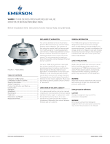
VAREC SERIES 5800B PRESSURE AND VACUUM RELIEF VALVE WITH FLAME ARRESTER ASSEMBLY
InstructIon, operatIon and maIntenance manual
DISCLAIMER OF WARRANTIES
The contract between Varec and our customer
states Varec’s entire obligation. The contents of
this instruction manual shall not become part
of or modify any prior or existing agreement,
commitment or relationship between Varec and
our customer. There are no express or implied
warranties set out in this instruction manual.
The only warranties that apply are those in
the existing contract between Varec and our
customer.
Emerson.com/FinalControl © 2017 Emerson. All rights reserved. VCIOM-03773-EN 17/07
Before installation these instructions must be fully read and understood
33-07767 Rev. G
LIMITATIONS OF SELLER’S LIABILITY
In the event that a court holds that this
instruction manual created some new
warranties, Seller's liability shall be limited
to repair or replacement under the standard
warranty clause. In no case shall Seller's
liability exceed that stated as Limitations of
Remedy in the contract between the Seller
andBuyer.
Use of parts that are not manufactured or
supplied by Varec voids any Varec warranty and
relieves Varec of any obligation to service the
product under warranty. Varec recommends
the use of only Varec manufactured or supplied
parts to maintain or service Varec 5800B Series
Pressure and Vacuum Relief Valve with Flame
Arrester Assembly.
This document, or any part of, may not be
reproduced by any means without written
permission of Varec, Inc.
TABLE OF CONTENTS
Disclaimer of warranties .................................... 1
Limitations of seller’s liability ............................ 1
Safety precautions .............................................. 2
Safety precaution definitions .............................. 2
General ................................................................ 2
Construction ........................................................ 2
Practical limitations ............................................ 4
Operation ............................................................. 5
Installation ........................................................... 5
Maintenance ........................................................ 8
Calibration ......................................................... 10
Replacement parts ........................................... 11
The Varec 5800B Pressure and Vacuum Relief
Valves with Flame Arrester Assembly have
not been tested by Varec under all possible
operational conditions, and Varec does not have
all the data relative to your application. The
information in this instruction manual is not
all-inclusive and does not and cannot take into
account all unique situations. Consequently,
you should review this product literature in
view of your application. If you have any further
questions, please contact Varec for assistance.

2
VAREC SERIES 5800B PRESSURE AND VACUUM RELIEF VALVE WITH FLAME ARRESTER ASSEMBLY
InstructIon, operatIon and maIntenance manual
GENERAL
The 5800B Series Pressure and Vacuum
Relief Valve and Flame Arrester Assembly is a
combination of the Varec 2010B/2020B Series
Pressure and Vacuum Relief Valve and the
Varec 5000 Series Flame Arrester. The unit
is designed to protect low-pressure storage
tanks, anaerobic digesters and gas-holders
from excessive pressure and/or vacuum.
In addition, it maintains system operating
pressure so biogas is not routinely vented to
atmosphere. The Flame Arrester protects from
accidental ignition of the sludge gas within
the low-pressure storage tank, anaerobic
digesters, and gas-holders. The Arrester is
designed to stop the propagation of flame from
external sources. The combination valve and
Flame Arrester is installed on the roof of low-
pressure storage tanks, anaerobic digesters
and gas-holders.
CONSTRUCTION
Refer to Figure 01 for construction and
assembly detail.
Standard materials of construction for the valve
include cast body and cover(s). Pallets are dead
weight loaded with lead or coated steel weights
and include a flexible membrane-sealing
insert. The pallet is loosely guided through a
center stem and pallet guide posts. Protective
screen is manufactured from high-density
polyethylene.
The Flame Arrester is constructed of a heavy
cast housing containing a removable multi-
plate bank assembly with an extensible
aluminum frame or a fixed stainless steel
frame.
The “All-Weather” Models 5811B and 5821B
Series Unit includes a special coating on
portions of the pallets, seat rings and guides
toeliminate ice accumulation.
The maximum working pressure for the 5800B
Series Unit is 2 PSIG (13.8 kPa). For material
selection see Product Data Sheet PDS 5810WT.
SAFETY PRECAUTION DEFINITIONS
CAUTION
Damage to equipment may result if this
precaution is disregarded.
WARNING!
Direct injury to personnel or damage to
equipment which can cause injury to personnel
may result if this precaution is not followed.
WARNING!
Flame Arresters are not capable of stopping
a flame front in mixtures of air with hydrogen,
acetylene, ethylene oxide, or carbon disulfide.
Note: Varec Flame Arresters bearing UL
approval are tested for use in oil storage tanks,
installed at no more than 15 feet from the open
end of a vent pipe (Reference UL 525). These
test conditions may not represent the actual
service conditions or piping system design. API
Publication 2028 states that the Flame Arrester
should be independently tested under actual
service conditions before installation.
SAFETY PRECAUTIONS
Read and understand this instruction manual
before installing, operating or performing
maintenance on Varec 5800B Series Pressure
And Vacuum Relief Valve With Flame Arrester
Assembly. Follow all precautions and warnings
noted herein when installing, operating or
performing maintenance on this equipment.
WARNING!
• Unit must be isolated from tank pressure before
servicing. All gas must be blocked and pressure
safely vented.
• Flame Arrester should be installed upstream
and no more than 15 feet from the ignition
source for use in accordance with UL approval.
• Flame Arresters are not capable of stopping
a flame front in mixtures of air with hydrogen,
acetylene, ethylene oxide, or carbon disulfide.
The 5810B Series Unit relieves pressure
directly to the atmosphere. A weatherhood
and mesh screen protects the valve pressure
pallet and guideposts. In-breathing ambient air
relieves vacuum pressure.
The 5820B Series Unit relieves pressure
through an enclosed outlet adapter. Product
vapors may be piped away rather than relieving
directly to the atmosphere. In-breathing
ambient air relieves vacuum pressure.

3
2" 23.12 9.88 21.75
(587) (251) (552)
3" 26.25 12.25 24.75
(667) (311) (629)
4" 31.25 12.44 29.5
(794) (316) (749)
6" 39.81 15.56 40.38
(1011) (395) (1026)
8" 49.12 19.56 49.5
(1248) (497) (1257)
10" 56.06 24.94 56.06
(1424) (633) (1424)
12" 67.31 29.38 66.44
(1710) (746) (1688)
VAREC SERIES 5800B PRESSURE AND VACUUM RELIEF VALVE WITH FLAME ARRESTER ASSEMBLY
InstructIon, operatIon and maIntenance manual
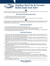
Dimensional layout and assembly
SIZES AND DIMENSIONS
Size
A
in. (mm)
B
in. (mm)
C
in. (mm)
2010 Series
pressure relief
and vacuum
breather valve
2020 Series
pressure relief
and vacuum
breather valve
MODEL 5810B 'VENT TO ATMOSPHERE' MODEL 5820B 'PIPE AWAY'
.6 THK gasket
.6 THK gasket
5000 Series
flame
arrester
5000 Series
flame
arrester
ANSI Class 150 drilling
aluminum: flat face
stainless steel: raised face
ANSI Class 150 drilling
aluminum: flat face
stainless steel: raised face
ANSI Class 150 drilling
aluminum flat face stainless
steel raised face
Mounting hardware
Mounting hardware

4
VAREC SERIES 5800B PRESSURE AND VACUUM RELIEF VALVE WITH FLAME ARRESTER ASSEMBLY
InstructIon, operatIon and maIntenance manual
PRACTICAL LIMITATIONS
While Flame Arresters decrease the possibility of flame propagation in a system, certain variables
must be evaluated to ensure safety. The relative fire hazard of flammable mixtures can be judged
by the upper and lower explosive limits. These limits are expressed as percents by volume of the
gas or vapor in air. The explosive range is that span of concentrations lying between the lower
and upper limits. The upper limit is the point at which the mixture is too rich to burn, i.e., contains
minimal oxygen to support combustion. The broader the explosive range, the easier it is to create
an air-gas explosive mixture. Conversely, when an explosive range is narrow, the chance of
developing a hazardous air-gas mixture disappears. Refer to Table 1 for lower and upper limits of
gases and vapors.
WARNING!
In all cases where the ratio of the upper limit/lower limit exceeds 10, the use of Flame Arresters is not
recommended. Also, the presence of any O
2
is dangerous because of the lack of homogeneity, which is
possible in gas mixtures. Any surplus of oxygen provides the potential for rapid explosion.
TABLE 1
Product
Limits in air percent
Product
Limits in air percent
Product
Limits in air percent
Lower Upper Lower Upper Lower Upper
Acetyldehyde 4.1 55.0 Ethyl-alcohol 4.3 19.0 Methyl-alcohol 7.3 36.0
Acetone 3.0 11.0 Ethyl-bromide 6.7 11.3 Methyl-chloride 10.7 17.4
Acetylene 2.5 81.0 Ethyl-chloride 3.8 15.4 Methyl-ethyl-ketone 1.8 10.0
Ammonia 15.0 28.0 Ethyl-ether 1.9 48.0 Methyl-formate 5.9 20.0
Benzene 1.4 7.1 Ethyl-formate 2.7 13.5 Methyl-propyl-ketone 1.5 8.0
Benzine 1.1 - Ethylene 3.1 32.0 Natural gas 3.8 17.0
Blast furnace gas 35.0 74.0 Furfural 2.1 - Noriane 0.8 -
Butadiene 2.0 11.5 Gasoline 1.4 7.6 Octane 1.0 -
Butane 1.9 8.5 Hexane 1.2 7.5 Pentane 1.5 7.8
Butylene 2.0 9.6 Heptane 1.2 6.7 Propane 2.1 9.5
Carbon disulphide 1.3 44.0 Hydrocyanic acid 6.0 41.0 Propyl-alcohol 2.1 13.5
Carbon monoxide 12.5 74.0 Hydrogen 4.0 75.0 Propylene 2.4 10.3
Cyclohexane 1.3 8.0 Hydrogen-sulphide 4.3 5.0 Pyridine 1.8 12.4
Cyclopropane 2.4 10.4 Isobutane 1.8 8.4 Styrene 1.1 6.1
Decane 0.8 5.4 Isopentane 1.4 7.6 Toluene 1.4 6.7
Ethane 3.0 12.5 Isopropyl-alcohol 2.0 12.0 Water gas 7.0 72.0
Ethyl-acentate 2.5 9.0 Methane 5.3 14.0 Xylene 1.0 6.0
Reference: Bureau of mines bulletin 503, limits of flammability of gases and vapors, 1952

5
VAREC SERIES 5800B PRESSURE AND VACUUM RELIEF VALVE WITH FLAME ARRESTER ASSEMBLY
InstructIon, operatIon and maIntenance manual
OPERATION
When the internal tank pressure approaches
the valve setting, the pressure pallet in the
valve begins to lift. As the pressure exceeds
the valve setting, the pressure pallet lifts
off the seat ring. Excess product vapor is
allowed to vent to the atmosphere, or through
the pipe away system adapter, relieving the
over pressure condition. The valve pallet
automatically re-seats as the tank pressure
drops below the valve setting.
If a vacuum within the tank approaches the
valve setting, the vacuum pallet in the valve
begins to lift. As the vacuum exceeds the valve
setting, the vacuum pallet lifts off the seat ring.
Atmospheric air is allowed to flow into the tank,
relieving the excess vacuum condition. The
pallet automatically re-seats as the vacuum
drops below the valve setting.
Flame Arresters in the unit does not prevent
the ignition of flammable mixtures, but
prevents the propagation of flame in case
of ignition. The Flame Arrester stops the
propagation of flame by absorbing and
dissipating heat through the surface area of the
bank sheets. Heat is absorbed as ignited gas
attempts to pass through the small passages
within the bank assembly. This action lowers
the temperature of the gas below its ignition
point and quenches the flame.
INSTALLATION
The 5800B Series Pressure and Vacuum
Relief Valve with Flame Arrester Assembly
must be mated with the appropriate flange(s).
Note that a Flame Arrester with aluminum
housing should be mated with an ANSI 125
Flat Face Flange. The 316 SS housing should
be mated with an ANSI 150 RF Flange. The
Flame Arrester must be located with clearance
allowed for removal of the bank assembly.
The nozzle must be plumb and the inlet flange
face level to ensure proper operation of the
pressure and vacuum relief valve.
1. Remove the unit from the shipping
container. Remove flange protectors.
Inspect for and remove any packing or other
loose material in the inlet/outlet chambers
of the Flame Arrester housing, and check
to see if extra loading weights for the valve
were bagged and packed separately.
2. Remove the weather hood and/or cover(s)
and all packing material above the pallets
and within the valve. Remove the cover and
extract bank assembly. Inspect for shipping
debris or damage, and correct as required.
Insert bank assembly and replace cover.
Install all cap screws hand tight. Cross
Tighten all cap screws evenly around cover
per Bolt Tightening Sequence. Torque to
40-50 ft·lbs.
BOLT TIGHTENING SEQUENCE

6
2” 8.3 4.8
3” 16.8 9.7
4” 22.1 12.8
6” 43.4 25.1
8” 72.7 42.0
10” 120.1 69.4
12” 179.9 104.0
VAREC SERIES 5800B PRESSURE AND VACUUM RELIEF VALVE WITH FLAME ARRESTER ASSEMBLY
InstructIon, operatIon and maIntenance manual
WARNING!
The aluminum back assembly weighs anywhere
from 10 to 80 pounds (4 to 40 kg). The 316 SS
assembly is substantially heavier. Use the
appropriate tools and equipment when handling
these units to avoid injury.
CAUTION
Whenever the valve weather hood and/or cover(s)
is removed and reinstalled, the end of the pallet
stem must engage the stem guide in the weather
hood and/or the stem guide chamber in the
cover(s) for proper seating and valve operation.
3. To load vacuum pallet weights on the valve,
perform the following:
a) With vacuum cover and gasket removed,
remove vacuum pallet assembly from
body.
b) Remove grip ring from pallet stem.
Note: spun sheet metal pallets have
a compensating weight on top of the
pallet. Do not remove this weight.
Refer to Table2 for incremental weight
information.
TABLE 2 - PALLET LOADING (INCLUDES WEIGHT OF PALLET)
Valve
size
Ounces of weight required
perounce of setting
Ounces of weight required
perinch of WC setting
Weight tolerance: + 5%/- 5%
Setting tolerance: + 0%/- 10%
c) Non-variable setting: locate weight
marked “Vacuum” and place on top
of compensating weight and/or pallet.
Secure with grip ring.
Note: if setting is less than 2” WC, weight
will be pre-loaded on the pallet.
d) Variable setting: each lead weight
is calibrated from 1” WC increment.
(Increments of ¼” WC and ½” WC may
be supplied on special order). Those
weights necessary for the initial specified
setting will be tagged separately from
any extra weight provided. Remove the
packaging on the weights tagged from
the initial specified setting and place
the weights on top of the compensating
weight. Secure with grip ring. Store
remaining weights for future use (in
casethe setting needs to be increased).
e) Weigh entire pallet assembly (including
installed weights). Using Table 2, confirm
that the assembly is the proper weight to
achieve the required setting. Allowable
weight tolerance is: +5%, -5%.

7
VAREC SERIES 5800B PRESSURE AND VACUUM RELIEF VALVE WITH FLAME ARRESTER ASSEMBLY
InstructIon, operatIon and maIntenance manual
4. To load pressure pallet weights on the valve,
perform the following:
a) With weather hood from Model 2010B, or
pipe away adapter cover and gasket from
Model 2020B removed, remove pressure
pallet assembly from body.
b) Remove grip ring from pallet stem.
Note: spun sheet metal pallets have
a compensating weight on top of the
pallet. Do not remove this weight.
Refer to Table2 for incremental weight
information.
c) Non-variable setting: locate weight
marked “Pressure” and place on top
of compensating weight and/or pallet.
Secure with grip ring. If setting is less
than 2” WC, weight will be pre-loaded
onthe pallet.
d) Variable setting: each lead weight
is calibrated from 1” WC increment.
(Increments of ¼” WC and ½” WC may
be supplied on special order). Those
weights necessary for the initial specified
setting will be tagged separately from
any extra weight provided. Remove the
packaging on the weights tagged from
the initial specified setting and place
the weights on top of the compensating
weight. Secure with grip ring. Store
remaining weights for future use (in case
the setting needs to be increased).
e) Weigh entire pallet assembly (including
installed weights). Using Table 2
(seepage 6), confirm that the assembly
is the proper weight to achieve the
required setting. Allowable weight
tolerance is: +5%, -5%.
f) Remove any remaining packing material
from valve body. Wipe pressure seat ring,
guide posts and pallet assembly with a
soft cloth to remove any material which
could affect valve operation.
g) Place pallet assembly on seat.
Ensure that pallet moves freely within
guideposts and rests flat on the seat
ring.
h) Replace the weatherhood on
Model2010B or the pressure cover and
gasket on Model 2020B. Tighten all nuts
and screws uniformly.
CAUTION
The end of the pallet stem must engage the stem
guide in the weather hood or the stem guide
chamber in the cover for proper seating and
valveoperation.
f) Remove any remaining packing material
from valve body. Wipe vacuum seat ring,
guide posts and pallet assembly with a
soft cloth to remove any material which
could affect valve operation.
g) Place pallet assembly on valve body seat.
Ensure that pallet moves freely within
guideposts and rests flat on the seat
ring.
h) Replace the cover gasket and cover.
Tighten cover screws uniformly. As
shown in Bolt Tightening Sequence
(seepage 5).
CAUTION
The end of the pallet stem must engage the stem
guide chamber in the cover for proper seating and
valve operation.
5. Place the valve in a level position. Reach up
through the inlet flange and carefully push
up on the pressure pallet, then lower it onto
the seat. Pallet should move up and down
freely and rest flat on the seat ring.
6. Check the vacuum pallet by using a non-
sparking tool, which will pass through the
center of the mesh screen. Push up on the
vacuum pallet, then lower it onto the seat.
Pallet should move freely and rest flat on
the seat ring.
7. Place the appropriate full-face flange
gasket (by others) on the flange.
CAUTION
Do not mate a flat face flange to a raised face
flange.
If it necessary to mate an ANSI Class 125 F.F.
flange with an ANSI Class 150 R.F. flange, use
the proper spacer to convert the raised face to a
flat face.
8. Verify that the unit is level to permit proper
operation of the valve pallets and the Flame
Arrester bank assembly can be readily
extracted for inspection and maintenance.
Install mounting hardware, and tighten
uniformly.
9. When using Model 5820B Series, install
connecting piping (if required) to outlet
flange. Use a full-faced gasket and tighten
all mounting hardware uniformly.
10. The unit is now installed and ready for use.
Note: it is recommended that steel and iron
valves be given a coat of paint immediately
after installation is completed. Apply paint
toexternal surfaces only.

8
VAREC SERIES 5800B PRESSURE AND VACUUM RELIEF VALVE WITH FLAME ARRESTER ASSEMBLY
InstructIon, operatIon and maIntenance manual
MAINTENANCE
The unit should be inspected and cleaned
at periodic intervals. The frequency of
inspection is determined by the application.
Consideration should be given to the amount
of nature of water or solids in the gas, and the
corrosiveness of the process stream. Most
importantly, the Flame Arrester bank sheets
must be kept clean to prevent a decrease in
gas flow through the system and loss of heat
absorbing efficiency.
Generally, the first inspection should be made
approximately 30 days after commissioning.
Subsequent inspections should be made
every 30 days unless excessive deposits or
foreign matter accumulation is apparent.
Thus,inspection frequency should be
increased. Adjust the inspection frequency to
ensure free and unrestricted flow through the
Flame Arrester.
WARNING!
Failure to properly maintain the unit could result
in reduction of safety and impairment of system
operation.
WARNING!
• The unit must be isolated from tank pressure
before servicing. All gas must be blocked and
pressure safely vented. If no isolation valve
is present, carefully open vacuum cover or
lift pressure pallet, allowing pressure to vent
slowly.
• Ensure that the Flame Arrester is cool after
afire.
• Wear appropriate gloves and/or breathing
apparatus if hazardous vapors are present.
A. Pressure and vacuum relief valve
1. To inspect valve proceed as follows:
a) Remove the weather hood and/or
cover(s).
b) Remove pallets one at a time. Identify the
pallets to ensure they are returned tothe
correct valve seat.
2. To replace pallet insert proceed as follows:
a) Remove weather hood and/or cover(s)
and then pallet assembly.
b) Remove nut from base of pallet stem.
Remove retainer plate and insert.
Clean all surfaces and threads. Install
new insert, handling carefully to avoid
damaging insert or pallet. Apply a bead
of silicone at base of pallet stem threads
prior to installing securing nut.
c) Reassemble pallet and place on seat
of valve body. Ensure pallet assembly
moves freely within guideposts and rests
flat on seat ring.
d) Reinstall weather hood and/or cover(s).
CAUTION
The end of the pallet stem must engage the stem
guide in the weather hood and/or the stem guide
chamber in the cover(s) for proper seating and
valve operation.
c) Inspect pallet inserts for ripples, tears,
or nicks, as well as seating surfaces for
debris, abrasion or pitting. Pallet edges
and guide posts should be free or burrs,
corrosion or other obvious damage.
Clean all components, replacing any
showing excess wear or damage. On
the “All-Weather” versions, inspect the
Teflon coating for any damage that would
affect operation.
d) Reassemble in reverse order.
CAUTION
The end of the pallet stem must engage the stem
guide in the weather hood and/or the stem guide
chamber in the cover(s) for proper seating and
valve operation.
CAUTION
During periods of freezing weather, extra
maintenance is required for Models
2010B/2020B/3500. Either remove the pallets or
apply generous portions of silicone grease to the
pallets, seat rings and guide posts. When using
silicone grease, inspect valves at least weekly.
This procedure is not required for “All-Weather”
Models 2011B, 2021B or 3501.

9
VAREC SERIES 5800B PRESSURE AND VACUUM RELIEF VALVE WITH FLAME ARRESTER ASSEMBLY
InstructIon, operatIon and maIntenance manual
4. To replace vacuum seat ring perform the
following:
a) Remove vacuum cover, spacer (high
setting), gaskets, pallet assembly,
screen retainer, screen and guide posts.
b) Remove seat ring from valve body. Clean
body-mating surface and apply a thin,
uniform coat of silicone evenly on mating
surfaces.
c) Install new seat ring carefully to avoid
distortion. Reassemble screen and
retaining ring to secure seat ring. Ensure
that seat is flush and level with valve
body.
d) Reassemble guides posts.
e) Place pallet assembly on valve body seat.
Ensure pallet assembly moves freely
within guideposts and rests flat on seat
ring.
f) Reassemble spacer, cover and gaskets.
CAUTION
The end of the pallet stem must engage the stem
guide chamber in the cover for proper seating and
valve operation.
B. Flame arrester
1. Remove the cover cap screws and cover
plate. Pull-out the bank assembly by
using the bank handle. If desired, the
bank assembly may be removed from
thehousing.
WARNING!
The aluminum back assembly weighs anywhere
from 10 to 80 pounds (4 to 40 kg). The 316 SS
assembly is substantially heavier. Use the
appropriate tools and equipment when handling
these units to avoid injury.
a) Aluminum Frame – extend the frame to
its full open position. Both sides of each
grid sheet may be inspected and cleaned
without removal from the frame.
b) 316 SS Frame – It is non-extensible and
must be disassembled to access the
bank sheets.
2. Check for corrosion, bent, warped, or
otherwise damaged sheets that could cause
an opening for a direct flame path. Replace
with a full bank sheet if necessary.
3. Bank assembly cleaning procedure is
based on the type of residue to be removed.
Determine if residue type is Group I, II, or
III. Follow the cleaning procedures for the
selected group.
WARNING!
Use all volatile and flammable solvents carefully
to avoid ignition or prolonged breathing. Use
protective clothing and gloves when using acid
toavoid burns from contact with skin.
3. To replace pressure seat ring perform the
following:
a) For Model 2010B, remove weather hood,
screen, spacer ring, pallet assembly and
guide posts. For Model 2020B, remove
pressure cover, spacer (high setting),
gaskets, pallet assembly, outlet adapter,
and guide posts.
b) Remove seat ring from valve body. Clean
body and outlet adapter mating surfaces
and apply a thin, uniform coat of silicone
evenly on mating surfaces.
c) Install new seat ring carefully to avoid
distortion. Reassemble guides posts
(2010B) or outlet adapter (2020B) to
secure seat. Ensure that seat is flush
and level with valve body.
d) Reassemble guides posts (2020B).
e) Place pallet assembly on valve body seat.
Ensure pallet assembly moves freely
within guide posts and rest flat on seat
ring.
f) Reassemble remaining parts in reverse
order.
CAUTION
The end of the pallet stem must engage the stem
guide in the weather hood or the stem guide
chamber in the cover for proper seating and valve
operation.
5. Seat ring repair:
a) Seat may be ground or ground and
lapped (in place) to improve seal. Use a
lapping plate and medium valve grinding
compound, applying light pressure.
b) Finish lapping with a fine compound.
Avoid scoring or removing excessive
amounts of material.
c) Clean all compound from valve parts.
d) Hand buff seat with a medium grade
`Scotch-Brite’ (#7447) pad and light oil.
CAUTION
Whenever the weather hood and/or cover(s) is
removed and reinstalled, the end of the pallet
stem must engage the stem guide in the weather
hood and/or the stem guide chamber in the
cover(s) for proper seating and valve operation.

10
VAREC SERIES 5800B PRESSURE AND VACUUM RELIEF VALVE WITH FLAME ARRESTER ASSEMBLY
InstructIon, operatIon and maIntenance manual
Group I
Residue type: soil, sand, pollen, and metallic
salts.
Cleaning procedure:
a) Wash bank sheets with a mild
solvent such as petroleum naptha or
commercial petroleum derived cleaning
fluids.
b) Rinse sheets with a solvent that does not
leave an oily film. This is necessary to
avoid collecting foreign matter.
c) Blow-out dry particles with compressed
air.
d) Wash bank sheets with hot water.
e) Steam bank assembly clean.
Group II
Residue type: metallic oxides and metallic
carbonates
Cleaning procedures:
a) Wash bank sheets as described in
GroupI, Step a.
b) Soak entire bank assembly in cold 35%
nitric acid.
CAUTION
Use acid only on aluminum or stainless steel bank
assemblies. Do not use on carbon steel or monel.
Note: if residue still remains, place the bank
assembly in boiling 35% nitric acid. Once all
residue is removed, soak the bank assembly
in a solution of baking soda and water
(8ounce baking soda to 3 gallons water) to
neutralize any remaining acid. Blow dry using
compressedair.
Group III
Residue type: organic tars, organic gums and
sulfur organic residues
Cleaning procedures:
a) Wash bank sheets as described in
GroupI, Step a.
b) Blow-out with compressed air.
c) Wash bank sheets with a strong
solvent such as benzol, xyol, carbon
tetrachloride, acetone, carbon disulfide,
paint thinner (not lacquer), or a mixture
of 1/3 each of benzol, alcohol and
acetone.
4. If residue cannot be removed by the above
procedures, replace with a new bank
assembly.
WARNING!
Clogged bank assembly can restrict the flow and
reduce its ability to stop flame propagation.
5. Place the bank assembly into the arrester
housing. Install new gasket, cover plate, and
cap screws.
a) Aluminum frame – it may not go entirely
back into place. The force needed to
compress the bank into place is supplied
by tightening cover plate cap screws.
b) 316 SS frame – the cover should close
readily.
6. Install all cap screws hand tight. Cross
tighten all cap screws evenly around cover
per Bolt Tightening Sequence (see page 5).
Torque to 40-50 ft·lbs.
7. The flame arrester is ready to be placed
back in service. Perform soap test. If any
leakage is detected, tighten the cap screws
again (maximum torque not to exceed
60ft·lb).
CALIBRATION
It is important to verify setting of the pressure
and vacuum relief valve of the assembly,
calculate the total necessary weight using
Table 2 (see page 6). Check this value against
the actual weight of the pallet assembly
(including loading weights). Adjust loading
weights as required per Installation Steps 3
or4.

11
2" 14.12 8.50 9.88 10.44
(359) (216) (251) (265)
3" 17.56 10.75 12.12 12.31
(446) (273) (311) (313)
4" 19.12 13.38 12.44 14.56
(486) (340) (316) (370)
6" 24.00 17.00 15.56 18.25
(610) (432) (395) (464)
8" 29.88 20.63 19.56 21.75
(759) (524) (497) (552)
10" 38.44 27.00 24.94 27.56
(976) (686) (633) (700)
12" 46.38 34.00 29.38 32.94
(1178) (864) (746) (837)
VAREC SERIES 5800B PRESSURE AND VACUUM RELIEF VALVE WITH FLAME ARRESTER ASSEMBLY
InstructIon, operatIon and maIntenance manual
SIZES AND DIMENSIONS
Size
A
in. (mm)
B
in. (mm)
C
in. (mm)
D
in. (mm)
FIGURE 1 - 2010B LOW SETTING
Drilling per ANSI Class 150
REPLACEMENT PARTS
Pressure and vacuum relief valve
A. Model 2010B
When ordering replacement parts, specify relief valve by model number, pipe size and serial
number. Identify replacement parts by part number, description and material where possible.

12
2" 14.12 8.50 9.88 13.31
(359) (216) (251) (338)
3" 17.56 10.75 12.25 15.25
(446) (273) (311) (387)
4" 19.12 13.38 12.44 17.25
(486) (340) (316) (438)
6" 24.00 17.00 15.56 21.56
(610) (432) (395) (548)
8" 29.88 20.63 19.56 24.81
(759) (524) (497) (630)
10" 38.44 27.00 24.94 29.50
(976) (686) (633) (749)
12" 46.38 34.00 29.38 32.94
(1178) (864) (746) (837)
VAREC SERIES 5800B PRESSURE AND VACUUM RELIEF VALVE WITH FLAME ARRESTER ASSEMBLY
InstructIon, operatIon and maIntenance manual
FIGURE 2 - 2010B HIGH SETTING
Drilling per ANSI Class 150
SIZES AND DIMENSIONS
Size
A
in. (mm)
B
in. (mm)
C
in. (mm)
D
in. (mm)

13
VAREC SERIES 5800B PRESSURE AND VACUUM RELIEF VALVE WITH FLAME ARRESTER ASSEMBLY
InstructIon, operatIon and maIntenance manual
TABLE 3 - MODEL 2010B REPLACEMENT PARTS
Item
No. Description Usage Material
Nominal pipe size
2” 3” 4” 6” 8” 10” 12”
1* Pressure pallet
assembly
Low set Alum. 06-11485-301 06-11485-401 06-11485-501 06-11485-601 06-11485-701 06-11485-801 06-11485-901
High set Alum. 06-11486-101 06-11486-201 06-11486-301 06-11486-401 06-11486-501 06-11486-601 06-11486-701
Low set 316 SST 06-11485-306 06-11485-406 06-11485-506 06-11485-606 06-11485-706 06-11485-806 06-11485-906
High set 316 SST 06-11486-106 06-11486-206 06-11486-306 06-11486-406 06-11486-506 06-11486-606 06-11486-706
2* Vacuum pallet
assembly
Low set Alum. 06-11485-101 06-11485-201 06-11485-001 06-11485-601 06-11485-701 06-11485-801 06-11485-901
High set Alum. 06-11486-101 06-11486-201 06-11486-301 06-11486-401 06-11486-501 06-11486-601 06-11486-701
Low set 316 SST 06-11485-106 06-11485-206 06-11485-006 06-11485-606 06-11485-706 06-11485-806 06-11485-906
High set 316 SST 06-11486-106 06-11486-206 06-11486-306 06-11486-406 06-11486-506 06-11486-606 06-11486-706
3* Seat ring All Alum. 02-10438-001 02-10251-001 02-05464-001 02-05478-001 02-05482-001 02-05487-001 02-05499-001
All 316 SST 02-10438-006 02-10251-006 02-05464-006 02-05478-006 02-05482-006 02-05487-006 02-05499-006
4 Pallet insert All PTFE 02-10361-093 02-09704-093 B12741-093 B12742-093 B12743-093 B12744-093 B13288-093
5 Pressure screen Low set HDPE 02-10439-051 02-10323-051 B16209-351 B14390-151 B14390-251 B14390-351 B14390-451
High set HDPE 02-10439-151 02-10323-151 B16209-451 B14390-551 B14390-651 B14390-751 B14390-451
6 Vacuum screen All HDPE 02-11547-051 02-11547-151 02-11547-251 02-11547-351 02-11547-451 02-11547-551 02-11547-651
7 Cover and spacer
gasket
Low set Fiber 02-11380-071 02-11381-071 02-11382-071 02-11383-071 02-11384-071 02-11385-071 02-11386-071
High set NBR 02-11380-075 02-11381-075 02-11382-075 02-11383-075 02-11384-075 02-11385-075 02-11386-075
8 Hood Low press.
set with low
vac set
Alum. 06-11136-01 06-11136-02 06-11136-08 06-11137-01 06-11137-02 06-11137-03 06-11137-04
Steel 02-10455-003 02-10310-003 02-10066-103 D6064-203 C6433-203 C6436-203 C6500-203
304 SST 02-10455-005 02-10310-005 02-10066-105 E2331-205 C7119-205 E2322-205 E2317-205
High press.
set with low
vac set
Alum. 06-11136-01 06-11136-02 06-11136-03 06-11137-01 06-11137-02 06-11137-03 06-11137-04
Steel 02-10455-003 02-10310-003 02-10066-103 D6064-203 C6433-203 C6436-203 C6500-203
304 SST 02-10455-005 02-10310-005 02-10066-105 E2331-205 C7119-205 E2322-205 E2317-205
Low press.
set with high
vac set
Alum. 06-11545-01 06-11545-02 06-11545-03 06-11137-05 06-11137-06 06-11137-07 06-11137-04
Steel 02-11197-003 02-11199-003 02-11045-203 02-11004-003 02-11006-003 02-11007-003 C6500-203
304 SST 02-11197-005 02-11199-005 02-11045-205 02-11004-005 02-11006-005 02-11007-005 E2317-205
High press.
set with high
vac set
Alum. 06-11545-01 06-11545-02 06-11545-04 06-11137-01 06-11137-02 06-11137-03 06-11137-04
Steel 02-11197-103 02-11199-103 02-11045-303 D6064-203 C6433-203 C6436-203 C6500-203
304 SST 02-11197-105 02-11199-105 02-11045-305 E24331-205 C7119-205 E2322-205 E2317-205
9* Press. guide post
(hood attm’t)
Low set 316 SST 02-11411-106 02-11411-206 02-11412-106 02-11413-106 02-11413-206 02-11415-106 02-11415-206
High set 316 SST 02-11411-306 02-11411-406 02-11412-206 02-11413-306 02-11413-406 02-11415-306 02-11415-206
10* Pressure guide
post
Low set 316 SST - - - 02-11414-106 02-11414-206 02-11416-106 02-11416-206
High set 316 SST - - - 02-11414-306 02-11414-406 02-11416-306 02-11416-206
11* Vacuum guide
post
All 316 SST 02-11015-106 02-11015-206 02-11432-106 B14384-106 B14384-206 B14384-506 02-11433-106
12 Spacer ring All Alum. - - - B14389-011 B14439-011 B14449-011 B16113-011
All Steel - - - B14389-003 B14439-003 B14449-003 B16113-003
All 316 SST - - - B14389-006 B14439-006 B14449-006 B16113-006
13 O-ring All NBR P014-03-285 P014-03-273 P014-03-286 P014-03-287 P014-03-288 P014-03-289 P014-03-290
14 Retaining ring All Polypropylene 02-11396 02-11397 02-11398 02-11399 02-11400 02-11401 02-11402
* For all weather parts, add -1 to end of listed part numbers.

14
2" 3" 4.94 5.25 9.06 6.75 14.15
(125) (133) (230) (171) (375)
3" 4" 6.38 5.88 10.81 8.38 18.56
(162) (149) (275) (213) (471)
4" 6" 8.75 6.81 12.81 8.44 20.44
(222) (173) (325) (214) (519)
6" 8" 8.56 10.00 18.81 10.50 24.25
(217) (254) (478) (267) (616)
8" 10" 11.19 12.12 22.12 13.12 30.75
(284) (308) (562) (333) (781)
10" 12" 13.63 16.25 27.56 16.88 38.56
(346) (413) (700) (429) (979)
12" 14" 15.38 18.88 32.06 19.75 44.75
(391) (480) (814) (502) (1137)
VAREC SERIES 5800B PRESSURE AND VACUUM RELIEF VALVE WITH FLAME ARRESTER ASSEMBLY
InstructIon, operatIon and maIntenance manual
FIGURE 3 - 2020B LOW SETTING
Drilling per ANSI Class 150
SIZES AND DIMENSIONS
Size
A
in. (mm)
B
in. (mm)
C
in. (mm)
D
in. (mm)
E
in. (mm)Inlet Outlet
B. Model 2020B
When ordering replacement parts, specify relief valve by model number, pipe size and serial number. Identify replacement parts by part number,
description and material where possible.
Outlet
Inlet

15
2" 3" 4.94 5.25 13.62 6.75 14.75
(125) (133) (346) (171) (375)
3" 4" 6.38 5.88 15.56 8.38 18.56
(162) (149) (395) (213) (471)
4" 6" 8.75 6.81 16.88 8.44 20.44
(222) (173) (429) (214) (519)
6" 8" 8.56 10.00 22.06 10.50 24.25
(217) (254) (560) (267) (616)
8" 10" 11.19 12.12 24.62 13.12 30.75
(284) (308) (625) (333) (781)
10" 12" 13.63 16.25 29.31 16.88 38.56
(346) (413) (744) (429) (979)
12" 14" 15.38 18.88 32.06 19.75 44.75
(391) (480) (814) (502) (1137)
VAREC SERIES 5800B PRESSURE AND VACUUM RELIEF VALVE WITH FLAME ARRESTER ASSEMBLY
InstructIon, operatIon and maIntenance manual
FIGURE 4 - 2020B HIGH SETTING
Drilling per ANSI Class 150
SIZES AND DIMENSIONS
Size
A
in. (mm)
B
in. (mm)
C
in. (mm)
D
in. (mm)
E
in. (mm)Inlet Outlet
Outlet
Inlet

16
VAREC SERIES 5800B PRESSURE AND VACUUM RELIEF VALVE WITH FLAME ARRESTER ASSEMBLY
InstructIon, operatIon and maIntenance manual
* For all weather parts, add -1 to end of listed part numbers.
TABLE 4 - MODEL 2020B REPLACEMENT PARTS
Item
no. Description Usage Material
Nominal pipe size (inlet x outlet)
2" x 3" 3" x 4" 4" x 6" 6" x 8" 8" x 10" 10" x 12" 12" x 14"
1* Pallet assembly Low set. Alum.
06-11485-101 06-11485-201 06-11485-001 06-11485-601 06-11485-701 06-11485-801 06-11485-901
High set. Alum.
06-11486-101 06-11486-201 06-11486-301 06-11486-401 06-11486-501 06-11486-601 06-11486-701
Low set. 316 SST
06-11485-106 06-11485-206 06-11485-006 06-11485-606 06-11485-706 06-11485-806 06-11485-906
High set. 316 SST
06-11486-106 06-11486-206 06-11486-306 06-11486-406 06-11486-506 06-11486-606 06-11486-706
2* Seat ring All Alum.
02-10438-001 02-10251-001 02-05464-001 02-05478-001 02-05482-001 02-05487-001 02-05499-001
All 316 SST
02-10438-006 02-10251-006 02-05464-006 02-05478-006 02-05482-006 02-05487-006 02-05499-006
3 Pallet insert All PTFE
02-10361-093 02-09704-093 B12741-093 B12742-093 B12743-093 B12744-093 B13288-093
4 Screen All HDPE
02-11547-051 02-11547-151 02-11547-251 02-11547-351 02-11547-451 02-11547-551 02-11547-651
5 Cover and spacer
gasket
Low set. Fiber
02-11380-071 02-11381-071 02-11382-071 02-11383-071 02-11384-071 02-11385-071 02-11386-071
High set. NBR
02-11380-075 02-11381-075 02-11382-075 02-11383-075 02-11384-075 02-11385-075 02-11386-075
6* Press. guide post All 316 SST
02-11015-106 02-11015-306 02-11432-106 B16553-406 B16553-206 B16553-506 02-11433-106
7* Vacuum guide post All 316 SST
02-11015-106 02-11015-206 02-11432-106 B14384-106 B14384-206 B14384-506 02-11433-106
8 O-ring All NBR
P014-03-285 P014-03-273 P014-03-286 P014-03-287 P014-03-288 P014-03-289 P014-03-290
9 Retaining ring All Polypropylene
02-11396 02-11397 02-11398 02-11399 02-11400 02-11401 02-11402
D. Model 5000/5010 flame arrester
When ordering replacement parts, specify
flame arrester by Model Number, Serial
Number, and pipe size. Identify replacement
parts by item number, description, and material
as shown on the reference drawings. Include
part numbers where possible.
TABLE 5 - MODEL 5000/5010 REPLACEMENT PARTS
5000 / 5010 2 3 4 6 8 10 12
Nominal pipe size
2 in 3 in 4 in 6 in 8 in 10 in 12 in
50 mm 75 mm 100 mm 150 mm 200 mm 250 mm 300 mm
Gasket kit: (2) cover w/(4) side plate:
non-asbestos
13-09101-02 13-09101-03 13-09101-04 13-09101-06 13-09101-08 13-09101-10 13-09101-12
Bank sheet set: aluminum BA17040 BA17046 BA17052 BA17058 BA17064 BA17070 BA17076
Bank sheet: 316 SS BA17044 BA17050 BA17056 BA17062 BA17068 BA17074 BA17080
Bank assembly: aluminum w/316 SS
sheet (extensible)
BM18996-000 BM18998-000 BM19000-000 BM18956-000 BM18958-000 BM19002-000 BM19004-000
Bank assembly: 316 SS (non-extensible) BM19882-600 BM19883-600 BM19884-600 BM19885-600 BM19886-600 BM19887-600 BM19888-600
Bank assembly: aluminum (extensible) BM6027 BM6055 BM6090 BM6126 BM6245 BM6269 BM6716
Bank assembly
Gasket
Gasket
5000 series vertical flame arrester
/