Page is loading ...

© 2022 Emerson. All rights reserved.Emerson.com
Before installation, these instructions must be carefully read and understood.
ANDERSON GREENWOOD 5910C PRESSURE/VACUUM RELIEF VALVE WITH INTEGRATED
FLAME ARRESTER (ATEX APPROVED)
TABLE OF CONTENTS
1. Disclaimer of Warranties ............................. 1
2. Limitations of Seller's Liability .................... 1
3. Safety Precautions ....................................... 2
4. Practical Limitations .................................... 2
5. General .......................................................... 2
6. Construction ................................................. 2
7. Operation ....................................................... 3
8. Installation .................................................... 3
9. Maintenance ................................................. 4
10. Parts List ....................................................... 6
11. Special Conditions for Safe Use .................. 7
WARNING
Failure to follow these instructions or to properly
install and maintain this equipment could result in
an explosion, fire and/or chemical contamination
causing property damage and personal injury or
death.
DISCLAIMER OF WARRANTIES
The contract between Anderson Greenwood
and our customer states Anderson
Greenwood’s entire obligation. The contents of
this instruction manual shall not become part
of or modify any prior or existing agreement,
commitment or relationship between Anderson
Greenwood and our customer. There are no
express or implied warranties set out in this
instruction manual. The only warranties that
apply are those in the existing contract between
Anderson Greenwood and our customer.
The Anderson Greenwood 5910C Pressure
and vacuum relief valves with flame arrester
assembly have not been tested by Anderson
Greenwood under all possible operational
conditions, and Anderson Greenwood does not
have all the data relative to your application.
The information in this instruction manual
is not all-inclusive and does not and cannot
take into account all unique situations.
Consequently, you should review this product
literature in view of your application. If you have
any further questions, please contact Anderson
Greenwood for assistance.
LIMITATIONS OF SELLER'S LIABILITY
In the event that a court holds that this
instruction manual created some new
warranties, Seller's liability shall be limited
to repair or replacement under the standard
warranty clause. In no case shall Seller's
liability exceed that stated as limitations of
remedy in the contract between the Seller and
Buyer. Use of parts that are not manufactured
or supplied by Anderson Greenwood voids any
Anderson Greenwood warranty and relieves
Anderson Greenwood of any obligation to
service the product under warranty. Anderson
Greenwood recommends the use of only
Anderson Greenwood manufactured or
supplied parts to maintain or service Anderson
Greenwood 5910C Series Pressure and Vacuum
relief valve with Flame Arrester assembly.
VCIOM-16612-EN 22/02
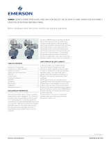
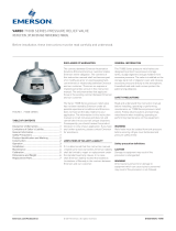
FIGURE 1
MODEL 5910C

2
ANDERSON GREENWOOD 5910C PRESSURE/VACUUM RELIEF VALVE WITH INTEGRATED
FLAME ARRESTER (ATEX APPROVED)
SAFETY PRECAUTIONS
Read and understand this instruction manual
before installing, operating or performing
maintenance on Anderson Greenwood 5910C
Series Pressure and vacuum relief valve with
flame arrester assembly. follow all precautions
and warnings noted herein when installing,
operating, or performing maintenance on this
equipment.
WARNING
• Failure to follow these instructions or to
properly install and maintain this equipment
could result in an explosion, fire and/or
chemical contamination causing property
damage and personal injury or death. Anderson
Greenwood™ flame arrestor must be installed,
operated and maintained in accordance with
federal, state and local codes, rules and
regulations, and Emerson instructions. Failure
to correct trouble could result in a hazardous
condition. Call a qualified service person
to service the unit. Installation, operation
and maintenance procedures performed by
unqualified person may result in improper
adjustment and unsafe operation. Either
condition may result in equipment damage or
personal injury. Only a qualified person must
install or service the flame arrestor.
• Unit must be isolated from tank pressure before
servicing. All gas must be blocked and pressure
safely vented.
• Flame Arresters are not capable of stopping
a flame front in mixtures of air with hydrogen,
acetylene, ethylene oxide, or carbon disulphide.
WARNING
The flame element assembly in this product is
validated and certified, per ISO 16852 to protect
against flame propagation
only
for Gas Group IIA.
PRACTICAL LIMITATIONS
While flame arresters decrease the possibility
of flame propagation in a system, certain
GENERAL
The 5910C is designed to protect low-pressure
storage tanks, anaerobic digesters and
gas-holders from excessive pressure and/
or vacuum. In addition, it maintains system
operating pressure, so gas is not routinely
vented to atmosphere. The flame arrester
element assembly protects from accidental
ignition of the gas within the low-pressure
storage tank, anaerobic digesters, and
gas-holderssimilar low-pressure storage
devices. The arrester is designed to stop the
propagation of flame from external sources.
The combination valve and flame arrester
is installed vertically on the roof of low
pressure storage tanks, anaerobic digesters
and gas-holders. The 5910C Series unit
relieves pressure directly to the atmosphere.
A weatherhood and mesh screen protects the
valve pressure pallet, and guideposts & flame
element assembly from contamination, nesting
animals, weather, etc. In-breathing ambient
air relieves vacuum pressure. Flame arresters
may be used in combination with additional
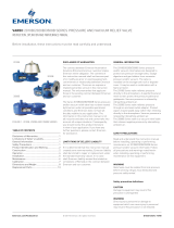
CONSTRUCTION
Refer to Figure 04 for construction and assembly
detail.
Standard materials of construction for the valve
include cast body and cover(s). Pallets are dead
weight loaded with lead or coated steel weights
and include a flexible membrane-sealing
insert. The pallet is loosely guided through a
center stem and pallet guide posts.
The maximum working pressure for the
5910C series unit is 2 psig (13.8 kpa). For
material selection see product data sheet.
Size A [mm] B [mm] C [mm] D1 [mm]
2" 445 390 251 329
3" 505 390 311 360
4" 588 543 316 430
6" 666 543 395 503
8" 818 642 497 577
Size A [in] B [in] C [in] D1 [in]
2" 17.52 15.35 9.88 12.95
3" 19.88 15.35 12.24 14.17
4" 23.15 21.38 12.44 16.93
6" 26.22 21.38 15.55 19.80
8" 32.20 25.28 19.57 22.72
1. Does not include coupling.
1. Does not include coupling.
Note: Minimum clearance for installation, to allow for appropriate air flow around the valve inlet
and outlet, should be 150 mm
protection measures, the overall safety of the
combined installation shall be assessed, taking
account of any hazardous area classification
(zones) and of the likelihood of possible ignition
sources.
WARNING
Ensure all selected materials are suitable for
the environment and processes for which they
are being installed. Attention must be paid
to selection of materials to ensure effective
operation of the valve and flame arrester
functionality.
variables must be evaluated to ensure safety.
The relative fire hazard of flammable mixtures
can be judged by the upper and lower explosive
limits. These limits are expressed as percent
by volume of the gas or vapor in air. The
explosive range is that span of concentrations
lying between the lower and upper limits. The
upper limit is the point at which the mixture
is too rich to burn, i.e., contains minimal
oxygen to support combustion. The broader
the explosive range, the easier it is to create
an air-gas explosive mixture. Conversely, when
an explosive range is narrow, the chance of
developing a hazardous air-gas mixture is
reduced.

3
ANDERSON GREENWOOD 5910C PRESSURE/VACUUM RELIEF VALVE WITH INTEGRATED
FLAME ARRESTER (ATEX APPROVED)
OPERATION
When the internal tank pressure approaches
the valve setting, the pressure pallet in the
valve begins to lift. As the pressure exceeds
the valve setting, the pressure pallet lifts
off the seat ring. Excess product vapor is
allowed to vent to the atmosphere, relieving
the over pressure condition. The valve pallet
automatically re-seats as the tank pressure
drops below the valve setting. If a vacuum
within the tank approaches the valve setting,
the vacuum pallet in the valve begins to lift.
As the vacuum exceeds the valve setting,
the vacuum pallet lifts off the seat ring.
Atmospheric air is allowed to flow into the tank,
relieving the excess vacuum condition. The
pallet automatically re-seats as the vacuum
drops below the valve setting. Flame element
assemblies integrated into the unit do not
prevent ignition of flammable mixtures but
provide protection from unconfined deflagration
from the outside atmosphere to the internal
tank space Flame Arresters in the unit do not
prevent the ignition of flammable mixtures but
prevents the propagation of flame in case of
ignition . The Flame Arrester element assembly
stops the propagation of flame by absorbing
and dissipating heat through the surface
area of the crimped foil. Heat is absorbed
as ignited gas attempts to pass through the
small passages within the element assembly.
This action lowers the temperature of the
gas below its ignition point and quenches the
flame. Also, 5910C models rated for short-time
burning provide protection from deflagration
when a stabilized burn condition exists on the
unprotected side of the element.
INSTALLATION (PLACING INTO SERVICE)
5910C Series pressure and vacuum relief valves
must be mated with the appropriate flange(s).
The valve is installed vertically. The nozzle
must be plumb and the inlet flange face level to
ensure proper operation of the relief valve. The
valve’s vacuum inlet and pressure outlet must
remain clear and at a reasonable distance
from any obstructions to ensure free and easy
access for maintenance and any obstructions
which may impair flame protection or flow.
1. Remove the valve from the shipping
container. Check to see if extra loading
weights were bagged and packed separately.
CAUTION
Whenever the flame element assembly and/or
cover(s) is removed and reinstalled, the end of the
pallet stem must engage the stem guide in the
flame element assembly and/or the stem guide
chamber in the cover(s) for proper seating and
valve operation.
4. To load pressure pallet weights, perform the
following:
a. With weatherhood and flame element
assembly removed, remove pressure
pallet assembly from body.
b. Remove grip ring from pallet stem.
c. Non-variable setting: locate weight
marked “PRESSURE” and place on top
of compensating weight and/or pallet.
Secure with grip ring. If setting is less
than 2” WC, weight will be pre-loaded on
the pallet.
d. Variable setting: each lead weight is
calibrated from 1” WC increment.
(Increments of ¼” WC and 1/2” WC may be
supplied on special order). Those weights
necessary for the initial specified setting
will be tagged separately from any extra
weight provided. Remove the packaging
on the weights tagged from the initial
specified setting and place the weights on
top of the compensating weight. Secure
with grip ring. Store remaining weights for
future use (in case the setting needs to be
increased).
e. Weigh entire pallet assembly (including
installed weights). Using Table 5, confirm
that the assembly is the proper weight to
achieve the required setting. Allowable
weight tolerance is +5%,-5%.
f. Remove any remaining packing material
from valve body. Wipe pressure seat ring,
guide posts and pallet assembly with a
soft cloth to remove any material which
could affect valve operation.
g. Place pallet assembly on seat. Ensure that
pallet moves freely within guide posts and
rests flat on the seat ring.
h. Replace the weatherhood and flame
element assembly.
CAUTION
The end of the pallet stem must engage the stem
guide chamber in the cover for proper seating and
valve operation.
CAUTION
The end of the pallet stem must engage the stem
guide in the flame element assembly or the stem
guide chamber in the cover for proper seating and
valve operation.
2. Remove the weatherhood, flame element
assembly and/or cover(s) and all packing
material above the pallets and within the
valve.
3. To load vacuum pallet weights, perform the
following:
a. With vacuum cover and gasket removed,
remove vacuum pallet assembly from
body.
b. Remove grip ring from pallet stem.
c. Non-variable setting: locate weight
marked “VACUUM” and place on top
of compensating weight and/or pallet.
Secure with grip ring. Note: if setting is
less than 2” WC, weight will be pre-loaded
on the pallet.
d. Variable setting: each lead weight is
calibrated from 1” WC increment.
(Increments of ¼” WC and ½” WC may be
supplied on special order). Those weights
necessary for the initial specified setting
will be tagged separately from any extra
weight provided. Remove the packaging
on the weights tagged from the initial
specified setting and place the weights on
top of the compensating weight. Secure
with grip ring. Store remaining weights for
future use (in case the setting needs to be
increased).
e. Weigh entire pallet assembly (including
installed weights). Using Table 5, confirm
that the assembly is the proper weight to
achieve the required setting. Allowable
weight tolerance is +5%,-5%.
f. Remove any remaining packing material
from valve body. Wipe vacuum seat ring,
guide posts and pallet assembly with a
soft cloth to remove any material which
could affect valve operation.
g. Place pallet assembly on valve body seat.
Ensure that pallet moves freely within
guide posts and rests flat on the seat ring.
h. Replace the cover gasket and cover.
Tighten cover screws uniformly.

4
ANDERSON GREENWOOD 5910C PRESSURE/VACUUM RELIEF VALVE WITH INTEGRATED
FLAME ARRESTER (ATEX APPROVED)
FIGURE 2
Rotate from the
vacuum bore on
the outboard screw
CAUTION
DO NOT MATE A FLAT FACE FLANGE TO A
RAISED FACE FLANGE.
If it necessary to mate an ANSI Class 125 F.F.
Flange with an ANSI Class 150 R.F. Flange, use
the proper spacer to convert the raised face to a
flat face.
NOTE
Although steel valves have a standard paint
system, it is recommended that steel valves be
inspected and touch-up applied if necessary.
Apply paint to external surfaces only.
10. Verify that the valve is level to permit proper
operation of the pallets. Install mounting
hardware and tighten uniformly.
11. Use a full faced gasket and tighten all
mounting hardware uniformly.
12. Metal parts insulated by gaskets should be
earthed where necessary.
MAINTENANCE (ASSEMBLING AND
DISMANTLING)
The valve should be inspected and cleaned
at periodic intervals. The first inspection
should be made approximately 30 days after
commissioning. Subsequent inspections should
be made every 30 days. The user may adjust the
schedule for his own convenience and safety,
depending upon the product being stored.
WARNING
• Relief valve must be isolated from tank pressure
before servicing. All gas must be blocked and
pressure safely vented. If no isolation valve is
present, carefully open vacuum cover or lift
pressure pallet, allowing pressure to vent slowly.
• Wear appropriate gloves and/or breathing
apparatus if hazardous vapors are present.
1. To inspect valve proceed as follows:
a. Remove the weatherhood and flame
element assembly and/or cover.
b. Remove pallets one at a time. Identify the
pallets to ensure they are returned to the
correct valve seat.
c. Inspect pallet inserts for ripples, tears,
or nicks, as well as seating surfaces for
debris, abrasion or pitting. Pallet edges
and guide posts should be free or burrs,
corrosion or other obvious damage.
Clean all components, replacing any
showing excess wear or damage.
d. Reassemble in reverse order.
CAUTION
The end of the pallet stem must engage the stem
guide chamber in the flame element assembly
and/or cover for proper seating and valve
operation.
CAUTION
During periods of freezing weather, extra
maintenance is required for 5910C Series. Either
remove the pallets or apply generous portions of
silicone grease to the pallets, seat rings and guide
posts. When using silicone grease, inspect valves
at least weekly. Extra attention must be given to
inspection of the Flame Cell Assembly to ensure
clear and consistent flow.
2. To replace pallet insert proceed as follows:
a. Remove weatherhood and/or cover(s)
and flame element assemblies and then
pallet assembly.
b. Remove nut from base of pallet stem.
Remove retainer plate and insert.
Clean all surfaces and threads. Install
new insert, handling carefully to avoid
damaging insert or pallet.
c. Reassemble pallet and place on seat of
valve body. Ensure pallet assembly moves
freely within guide posts and rests flat on
seat ring.
d. Reinstall flame element assembly,
weatherhood and/or cover(s).
5. Place the valve in a level position. Reach up
through the inlet flange and carefully push
up on the pressure pallet, then lower it onto
the seat. Pallet should move up and down
freely and rest flat on the seat ring.
6. Remove all vacuum element screws from
the body except for the furthest outboard.
Loosen the outboard screw only enough to
allow the vacuum flame element assembly
and gasket to rotate away from the valve
vacuum bore. (Figure 02)
7. Reach up through the vacuum bore and
carefully push up on the vacuum pallet, then
lower it onto the seat. Pallet should move up
and down freely.
8. Rotate the element assembly and gasket
back into place and re-install all screws.
9. Mount the valve on the flanged nozzle using
the appropriate gasket.
CAUTION
The end of the pallet stem must engage the stem
guide chamber in the flame element assembly for
proper seating and valve operation.
3. To replace pressure seat ring perform the
following:
a Remove weatherhood, screen, flame
element assembly, spacer ring (if
applicable), pallet assembly, guide posts,
shroud assembly, and seat gasket.
b. Remove seat ring and O-Ring from valve
body. Clean body, outlet adapter mating
surfaces and O-Ring Groove.
c. Install new O-Ring into groove; ensure
that the O-Ring stays properly in groove
while installing seat ring.
d. Install new seat ring carefully to avoid
distortion. Reassemble seat gasket,
shroud assembly, guide posts and spacer
ring (if applicable) to secure seat. Ensure
that seat is flush and level with valve
body.
e. Place pallet assembly on valve body seat.
Ensure pallet assembly moves freely
within guide posts and rests flat on seat
ring.
f. Reassemble remaining parts in reverse
order.
CAUTION
The end of the pallet stem must engage the stem
guide chamber in the flame element assembly for
proper seating and valve operation.

5
ANDERSON GREENWOOD 5910C PRESSURE/VACUUM RELIEF VALVE WITH INTEGRATED
FLAME ARRESTER (ATEX APPROVED)
CAUTION
The end of the pallet stem must engage the stem
guide chamber in the cover for proper seating and
valve operation.
CAUTION
Whenever the flame element assembly and/or
cover(s) is removed and reinstalled, the end of the
pallet stem must engage the stem guide chamber
in the flame element assembly and/or the stem
guide chamber in the cover(s) for proper seating
and valve operation.
Flame Element Assembly – Cleaning &
Maintenance
1. Carefully remove the element assembly from
the arrestor and place it on a soft surface
such as plywood.
2. Inspect the flame cell visually for any signs of
corrosion or other damage.
3. Inspect the flame cell with a calibrated
pin gauge to ensure maximum crimp size
openings do not exceed the following values
for their respective gas group:
• Explosion Group IIA / D – 0.024 in. / 0.8 mm
(Pressure Side Element)
• Explosion Group IIA / D – 0.043 in. / 1.14 mm
(Vacuum Side Element)
4. If any damage is noted, or crimp openings
exceed maximum size allowable, replace the
element assembly.
5. Keep the element openings clean to
prevent loss of efficiency in absorbing heat.
Remove the element assembly and clean
the elements to prevent the openings from
becoming clogged with particulate matter.
Clean the element with a suitable cleaning
media (solvent, soap, water, steam or
ultrasonic) then blow dry using compressed
air. Be careful not to damage or dent the
cell openings as this would hamper the
effectiveness of the unit. Do not clean the
arrestor elements by rodding to remove
blockages, as this practice will damage the
elements and seriously impair the arrestor’s
performance. If the arrestor element cannot
be cleaned satisfactorily, replace it.
6. High-pressure water jets are NOT
recommended
7. The cleaning interval should be governed
by the amount and type of particulate in
the system to which it is installed and must
be determined by the user. To determine
the maintenance interval, the user should
check the element in the first few months
of operation to find how quickly particulate
accumulates in the cells.
8. After cleaning, thoroughly inspect the
element for damage. If damaged, replace it.
5. Seat ring repair:
a. Seat may be ground or ground and
lapped (in place) to improve seal. Use a
lapping plate and medium valve grinding
compound, applying light pressure.
b. Finish lapping with a fine compound. Avoid
scoring or removing excessive amounts of
material.
c. Clean all compound from valve parts.
d. Hand buff seat with a medium grade
`Scotch-Brite’ (#7447) pad and light oil.
NOTE
Under no circumstance should the element
bank be disassembled from its shell for cleaning
or replacement. The element section must be
replaced as a complete assembly.
CAUTION
If deflagration or stabilised burning is found to
have occured, the flame element assembly should
be replaced.
4. To replace vacuum seat ring perform the
following:
a. To replace vacuum side seat, it is only
necessary to remove the vacuum-side
element assembly & seat gasket. The
seat will drop right out. No need to
remove guide posts on vacuum side.
b. Remove flame element assembly, seat
gasket, seat ring and O-Ring from valve
body. Clean body mating surface and
O-Ring groove.
c. Install new O-Ring into groove; ensure that
the O-Ring stays properly in groove while
installing seat ring.
d. Install new seat ring carefully to avoid
distortion. Reassemble flame element
assembly and seat gasket to secure seat
ring. Ensure that seat is flush and level
with valve body.
e. Place pallet assembly on valve body seat.
Ensure pallet assembly moves freely
within guide posts and rests flat on seat
ring.
f. Reassemble cover and gasket.
g. Remove all vacuum element screws from
the body except for the furthest outboard.
Loosen the outboard screw only enough
to allow the vacuum flame element
assembly and gasket to rotate away from
the valve vacuum bore. (Figure 02)
h. Reach up through the vacuum bore and
carefully push up on the vacuum pallet,
then lower it onto the seat. Pallet should
move up and down freely.
i. Rotate the element assembly and gasket
back into place and re-install all screws.

6
ANDERSON GREENWOOD 5910C PRESSURE/VACUUM RELIEF VALVE WITH INTEGRATED
FLAME ARRESTER (ATEX APPROVED)
PARTS LIST
Item No. Description
1 Body
3Seat Ring
4Guide Post, Vacuum
5Guide Post, Pressure
6Guide Post, Pressure
7Pallet Stem
8Pallet
9A Insert (FEP)
9B Insert
10 Insert Retainer
13 Screen, Pressure
14 Hood
16 Cover
17 Gasket
19 Spacer, Ring
21 Name Plate
22 Warning Label
24 Grip Ring
25 Stud
FIGURE 4
CONSTRUCTION AND ASSEMBLY DETAIL
26 Nut
28 Nut
30 Screw Cap Hex
31 Screw Cap Hex
34 Screw Cap Hex
35 Pallet Stem
37 Insert Retainer
38 Pallet
39 O-ring
40 Washer
42 Washer
43 Shroud
44 Drain
45 Standoff
46 Element Assembly, Pressure
47 Element Assembly, Vacuum
48 Gasket, Pressure
49 Gasket, Seat
50 Plug
Item No. Description

7
ANDERSON GREENWOOD 5910C PRESSURE/VACUUM RELIEF VALVE WITH INTEGRATED
FLAME ARRESTER (ATEX APPROVED)
SPECIAL CONDITIONS FOR SAFE USE
Marking on Pressure/Vacuum Relief Valve with integrated Flame Arrester (ATEX Approved)
For IIA only the manufacturing is intended for sizes 2" (DN 50) to 8" (DN 200) for Types 5910C
WARNING
FLAME ARRESTERS HAVE INSTALLATION AND APPLICATION LIMITS
TYPE DESIGNATION IN ACCORDANCE WITH ISO 16852
DEF LU/D = N/A BC: c
Ex. Gp IIA T0 = 60°C
WARNING
FLAME ARRESTERS HAVE INSTALLATION AND APPLICATION LIMITS
TYPE DESIGNATION IN ACCORDANCE WITH ISO 16852
DEF LU/D = N/A BC: b; tBT = 1 min
Ex. Gp IIA T0 = 60°C
Warning label for 5910C without short time burn protection
Warning label for 5910C with short time burn protection
WARNING PLATE INFORMATION EXPLAINED
WARNING PLATE FIELD MARKING
DEF "DEF" - Deflagration
LU/D "N/A" - Suitable for End of Line use only
BC* "b" - Short time burn (1 minute)
"c" - no burn time
Ex. Gp "IIA" - Suitable for MESG ≥0.94 mm
T0"60°C" - Maximum Operational Temperature
* For short time burning flame arresters, additional external safety equipment is required, such as a
temperature sensor. Additional safety equipment is required to ensure appropriate corrective measures
are taken within 0.5 x tBT to protect the system if an abnormal temperature is detected. Never disconnect or
remove these devices in active process system.

8
ANDERSON GREENWOOD 5910C PRESSURE/VACUUM RELIEF VALVE WITH INTEGRATED
FLAME ARRESTER (ATEX APPROVED)
SPECIAL CONDITIONS FOR SAFE USE (CONTINUED)
All 5910C deflagration elements are rated
for short time burning, tBT not to exceed one
minute in accordance with EN ISO 16852:2016.
These burn times were determined at
atmospheric pressure. If there are operating
conditions which can lead to a stabilized
burning event, additional safety measures are
required. The devices shall be equipped with
temperature sensors in the hood such that
the atmospheric side of the flame cell can be
monitored. These temperature sensors are
installed into the system in such a way that
they trigger the initiation of measures for
the elimination of the stabilized burning (for
example, emergency functions like switching-
off the system, inerting or similar). These
measures must occur within half of the time
for which the flame arrester is short-time burn
proof (0.5 x tBT). See Figure 03 for warning
label showing burn rating, tBT. This requires
that measures must be able to be taken within
30 seconds.
Threaded instrumentation ports, with standard
1/2 NPT threads, are integrated into each hood.
Other instrumentation port thread sizes can be
requested.
If the user requests the addition of temperature
sensors by Emerson, they will either be
installed and shipped threaded into the
appropriate instrumentation port in the
flame arrester hood or shipped separately
with the flame arrester. To install the
temperature sensors that have been shipped
separately, simply remove any protective
packaging from the temperature sensors
and thread the temperature sensors into the
appropriate threaded instrumentation ports
in the flame arrester hood making sure to
follow temperature sensor manufacturer’s
instructions, particularly for wiring.
The temperature sensor shall be installed on
the downstream or unprotected (“hot”) side of
the flame arrester. For end of line deflagration
flame arresters this is the atmospheric side
of the flame arrester and the only location
available. If the temperature sensor is shipped
separately, the user shall be responsible
for installing the temperature sensor in the
appropriate instrumentation port in the hood of
the flame arrester.
If a temperature sensor is not requested with
the flame arrester then the end user shall be
responsible for installation of the temperature
sensor on the unprotected (“hot”) side of
flame arrester. This is the side of the flame
arrester closest to the source of ignition
TABLE 5. TEMPERATURE SENSOR SAFETY SPECIFICATIONS
TECHNICAL DATA THERMOCOUPLE
Design Type Standard with Thermowell Standard without Thermowell
Model 185 03J1 Code 0185 thermocouple (IEC 584
Class 1) without thermowell
Manufacturer Emerson Rosemount Emerson Rosemount
EC-type approval certificate
FM12ATEX0065X
ATEX: EN 60079-0:2012+A11:2013;
EN 60079-1: 2014
FM12ATEX0065X
ATEX: EN 60079-0:2012+A11:2013;
EN 60079-1: 2014
Temperature sensor design Type-K thermocouple Type-K thermocouple
Type of ignition protection
II 2 G Ex d IIC T6...
T1 Gb, T6(–50°C ≤ Ta ≤ + 40°C), T5...
T1 (–50 °C ≤ Ta ≤ + 60°C)
II 2 G Ex d IIC T6...
T1 Gb, T6(–50°C ≤ Ta ≤ + 40°C), T5...
T1 (–50°C ≤ Ta ≤ + 60°C)
Protection type
(connection head)
Rosemount Aluminum
Explosion proof, 2-wire, 3-wire,
4-wire type A, 4-Wire type as
specified by customer.
Intrinsically safe option is available
Rosemount Aluminum
Explosion proof, 2-wire, 3-wire,
4-wire type A, 4-Wire type as
specified by customer.
Intrinsically safe option is available.
Measuring probe
(measuring insert)
1/2 NPT or optional M24 x1.5.
Intended for installation into
thermowell.
Probe length varies by flame arrester
size. Adjustable insertion length.
Connection thread 1/2 NPT. Intended for installation
into thermowell.
1/2 NPT. Intended for installation
without thermowell.
Transmitter Optional by customer request. Optional by customer request.
Intended application In-line flame arresters and
detonation arresters
End-of-line flame arresters.
Free-vent style.
Model TC 10-2 (for additional Thermowell) TC10-H (threaded for direct insertion
without thermowell)
Manufacturer WIKA WIKA
EC-type approval certificate ATEX and IECEx certifications ATEX and IECEx certifications
Temperature sensor design Type-K thermocouple Type-K thermocouple
Type of ignition protection
II 2 G Ex d IIC T6...
T1 Gb, T6(–50°C ≤ Ta ≤ + 40°C), T5...
T1 (–50°C ≤ Ta ≤ + 60°C)
II 2 G Ex d IIC T6...
T1 Gb, T6(–50°C ≤ Ta ≤ + 40°C), T5...
T1 (–50°C ≤ Ta ≤ + 60°C)
Protection type
(connection head)
Explosion proof, 2-wire, 3-wire,
4-wire type A, 4-Wire type as
specified by customer.
Intrinsically safe option is available.
Explosion proof, 2-wire, 3-wire,
4-wire type A, 4-Wire type as
specified by customer.
Intrinsically safe option is available.
Measuring probe
(measuring insert)
Spring loaded plate. Probe allows
use of transmitter. Length varies by
flame arrester size.
Probe length varies by flame arrester
size. Adjustable insertion length.
Connection thread
1/2 NPT or optional M24 x1.5.
Intended for installation
into thermowell.
1/2 NPT. Intended for installation
without thermowell.
Transmitter Optional by customer request. Optional by customer request.
Intended application In-line flame arresters and
detonation arresters.
End-of-line flame arresters.
Free-vent style.

9
ANDERSON GREENWOOD 5910C PRESSURE/VACUUM RELIEF VALVE WITH INTEGRATED
FLAME ARRESTER (ATEX APPROVED)
D104601X012 © 2022 Emerson Electric Co. All rights reserved 02/22. Anderson Greenwood is a mark owned by one of the companies in the Emerson
Automation Solutions business unit of Emerson Electric Co. The Emerson logo is a trademark and service mark of Emerson Electric Co. All other
marks are the property of their prospective owners.
The contents of this publication are presented for informational purposes only, and while every effort has been made to ensure their accuracy,
they are not to be construed as warranties or guarantees, express or implied, regarding the products or services described herein or their use or
applicability. All sales are governed by our terms and conditions, which are available upon request. We reserve the right to modify or improve the
designs or specifications of such products at any time without notice.
Emerson Electric Co. does not assume responsibility for the selection, use or maintenance of any product. Responsibility for proper selection, use
and maintenance of any Emerson Electric Co. product remains solely with the purchaser.
Emerson.com
and is the atmospheric side for end of line
deflagration flame arresters. A temperature
rise of 20 K (36°F / 20°C) above the flame
arrester maximum operating temperature
or 20 K (36°F / 20°C) above the process
operating temperature, whichever is lower
but not to exceed 20 K (36°F / 20°C) above
the flame arrester operating temperature,
is the recommended activation temperature
for initiation of measures against stabilized
burning.
Note that a rise in temperature measured by
the temperature sensor can indicate to the
user deflagration and/or detonation events
have occurred as well. This should be used
as a trigger to investigate what conditions
have lead to ignition of flammable vapors, to
inspect the flame arrester for damage, and to
initiate appropriate corrective actions relative to
process system and safety.
Temperature sensors installed by the user
shall follow the specifications in Table 5.
Different temperature sensors may be installed
by the end user; however these must comply
with the safety specifications in Table 5. The
use of alternate temperature sensors must
include evidence of equivalent response rates
to the specified sensors in Table 5, particularly
as the 5910C end of line deflagration flame
arrester is rated for short time burning. If tBT is
exceeded during a short-time burning situation,
the flame arrester safety cannot be assured.
If an elevated temperature has been detected
by the temperature sensor, whether due to
flash back or stabilized burn, the temperature
sensor shall be inspected for damage and
replaced as necessary. If the recorded
temperature exceeds the design temperature
of the temperature sensor then the measuring
probe shall be replaced.
SPECIAL CONDITIONS FOR SAFE USE (CONTINUED)
MARKING PLATE FIELD MARKING
MODEL Per Order, ex. 5910C
SIZE Per Order, ex. 6 in.
Date Of Manufacture (D.O.M) Date of manufacture
Serial Number (S/N) Per Order
STANDARD Standard certified in accordance with
SETTING (PRESS/VAC) Relief Valve Set Pressures
AIR FLOW RATE Rated capacity at the indicated relief pressure
Eu-Type Examination Certificate Based on unit ordered
UKCA – Type Examination Certificate Based on unit ordered
/