Page is loading ...

STV-065
SOPORTE DE TECHO PARA
PANTALLAS DE 32” A 65”
V1.00119m
Manual de instrucciones
• Este aparato no se destina para utilizarse por personas (incluyendo niños) cuyas capacidades
físicas, sensoriales o mentales sean diferentes o estén reducidas, o carezcan de experiencia o
conocimiento.
• Los niños deben supervisarse para asegurar que no empleen el aparato como juguete.
• Este producto está diseñado para uso en interiores.
• El soporte debe ser instalado sobre una superficie sólida.
• No debe excederse la capacidad de carga máxima (40 kg).
HERRAMIENTAS NECESARIAS PARA LA INSTALACIÓN
Utiliza el soporte de techo como plantilla
para realizar las marcas de las perforaciones
en el lugar donde deseas instalarlo.
Selecciona 2 orificios de cada lado.
1
2
Ensambla el soporte de techo y el primer segmento de la barra
telescópica, como se muestra en la figura.
3
INSTALACIÓN
Steren no se hace responsable por daños materiales ni personales causados por mal uso o mala instalación. Es
responsabilidad del usuario asegurarse de la correcta instalación y uso del producto, así como de su revisión periódica.
Los tornillos suministrados son de medidas estándar. Te recomendamos consultar el manual de instrucciones de tu
pantalla para obtener información acerca de los tornillos necesarios para montarla en un soporte.
No instales pantallas de más de 65” ni con un peso mayor a 40 Kg
Asegúrate de que las barras queden
perfectamente acopladas
IMPORTANTE CONTENIDO
Antes de utilizar el producto, lee cuidadosamente este manual para evitar cualquier mal
funcionamiento.
La información presentada sirve únicamente como referencia sobre el producto; debido a
actualizaciones pueden existir diferencias.
Consulta nuestra página web www.steren.com para obtener la versión más reciente de este
manual.
PRECAUCIONES
Barras de sujeción
(2 piezas)
Soporte de pantalla
(1 pieza)
Soporte de techo
(2 segmentos)
Barra telescópica
(2 segmentos)
Nivel
(1 pieza)
M4x20 mm
A (4 piezas)
M6
G (4 piezas)
M8
I (4 piezas)
M8
J (4 piezas)
M6
K (4 piezas)
M8
L (4 piezas)
M6x20 mm
B (4 piezas)
M8x25 mm
C (4 piezas)
M6x8 mm
D (2 piezas)
M8
E (4 piezas)
M6x40 mm
F(4 piezas)
TORNILLOS
RONDANAS, BUJES, TUERCAS Y TAQUETES
PIEZAS
M6
H (4 piezas)
60 mm
ø10 mm
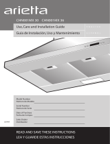
Realiza las perforaciones a una profundidad
de 60 mm, con una broca de 10 mm de
diámetro.
4
Introduce los taquetes (L) en los orificios realizados, y
fija la pieza con los tornillos (E) y las rondanas (I).
Techo de
concreto
Complementa la barra telescópica, con el segundo segmento y el soporte de pantalla a la
altura deseada. Fija ambas piezas usando los tornillos (F), las rondanas (H) y las tuercas (K).
5
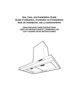
Utiliza 4 tornillos (A o B), los 4 bujes separadores (J) y las 4 rondanas (G) para fijar las
barras en la parte posterior de la pantalla. En caso de requerir tornillos más anchos, sólo
utiliza los tornillos (C) y los bujes separadores (J), sin las rondanas.
6
Afloja los tornillos de sujeción, y monta la pantalla sobre el soporte colocando primero la
parte superior de las barras (en forma de gancho) y, posteriormente, la parte inferior.
7
F
H
H
K
F
K
D
A,B o C
L
I
E
Ajusta la inclinación de
la pantalla, al aflojar y
apretar las mariposas
J
G
Observa que la burbuja esté en el centro,
para corroborar que el soporte esté nivelado
Aprieta los tornillos
para fijar la pantalla
Afloja los tornillos (D) para
girar la pantalla. Vuelve a
apretarlos para que quede fija
D
K
F
Ajusta la altura quitando
los tornillos (F) y las
tuercas (K)

STV-065
32” TO 65” CEILING MOUNT
V1.00119m
Instruction manual
• This device is not intended for use by persons (including children) whose physical, sensory
or mental abilities are different or reduced, or who lack experience or knowledge.
• Children should be supervised to ensure they do not use the device as a toy.
• This product is designed for indoor use.
• The support must be installed on a solid surface.
• The maximum load capacity (40 kg) must not be exceeded.
NECESSARY TOOLS FOR INSTALLATION
Use the ceiling stand as a template to make
the perforation marks in the place where
you want to install it. Select 2 holes on each
side.
1
2
Assemble the ceiling stand and the first segment of the
telescopic bar, as shown in the figure.
3
INSTALLATION
Steren is not responsible for material or personal damages caused by misuse or improper installation. It is the
responsibility of the user to ensure the correct installation and use of the product, as well as its periodic review.
The screws supplied are standard sizes. We recommend you consult the instruction manual of your screen to obtain
information about the screws necessary to mount it in a support.
Do not install screens over 65 "or weighing more than 40 Kg
IMPORTANT CONTENT
Before using the product, read this manual carefully to avoid any malfunction.
The information presented serves only as a reference on the product; Due to updates there
may be differences.
Check our website www.steren.com for the latest version of this manual.
CAUTIONS
Holding bars
(2
pieces)
TV stand
(1 piece)
Ceiling stand
(2 segments)
Telescopic bar
(2 segments)
Level
(1 piece)
M4x20 mm
A (4 pieces)
M6
G (4 pieces)
M8
I (4 pieces)
M8
J (4 pieces)
M6
K (4 pieces)
M8
L (4 pieces)
M6x20 mm
B (4 pieces)
M8x25 mm
C (4 pieces)
M6x8 mm
D (2 pieces)
M8
E (4 pieces)
M6x40 mm
F(4 pieces)
SCREWS
WASHERS, HUBS, NUTS AND ANCHORS
PIECES
M6
H (4 pieces)
60 mm
ø10 mm
Perform the holes to a depth of 60 mm, with
a drill of 10 mm in diameter.
4
Insert the anchors (L) into the holes made, and fix the
part with the screws (E) and the washers (I).
Concrete
ceiling
Complements the telescopic bar, with the second segment and the screen support at the
desired height. Fix both parts using the screws (F), the washers (H) and the nuts (K).
5
Use 4 screws (A or B), the 4 hub spacers (J) and the 4 washers (G) to fix the bars on the
back of the screen. If you require wider screws, only use the screws (C) and the hub spacers
(J), without the washers.
6
Loosen the fixing screws, and mount the screen on the support by first placing the upper
part of the bars (in hook form) and then the lower part.
7
F
H
H
K
F
K
D
A,B o C
L
I
E
J
G
Observe that the bubble is in the center,
to verify that the support is level
Make sure that the bars
are perfectly coupled
Adjust the tilt of the
screen, by loosening
and tightening the
butterflies
Tighten the screws
to fix the screen
Loosen the screws (D) to rotate
the screen. Tight them so that it
stay fixed
D
K
F
Adjust the height by
removing the screws (F)
and the nuts (K)
/