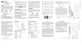
Page is loading ...

1 010-353-B1-001, Rev. C (5/2019)
FlexPoint
™
1215, 1232, 1250 Power Supplies Quick Start Guide
Review the drawings and illustrations contained in this guide before proceeding. For additional details on installation and
operation, visit www.alpha.com and download a copy of the FlexPoint
TM
1215, 1232, 1250 Series Technical Manual (p/n
010-353-B0).
The FlexPoint 1215, 1232 and 1250 power supplies are designed to provide 12Vdc primary and standby power to an
optical network terminal (ONT). These power supplies are able to provide 15W, 32W, and 50W output power, respectively,
via the 7-pin connector. A customer-provided 90Vac to 264Vac, 50/60Hz power receptacle provides primary power to the
input of the unit. The AC voltage is then converted to a usable 12Vdc output. Power status is provided to the customer via
audible alarms and visual indicators. Upon loss of AC service, the standby time is a function of the unit’s battery capacity
and the connected load.
1. Unpack and inspect the FlexPoint power supply.
2. Install the unit within 8' (2.4 m) to an AC outlet with 6" (15.2 cm) of space above and below, 2–4" (5–10 cm) in front
and 2" (5 cm) of space on either side to provide adequate thermal ventilation.
3. Remove battery compartment cover by pressing the nger tab underneath the middle of the unit and pull the cover
bottom away from the unit and down.
4. Determine the necessary cable length to provide appropriate service loops between the unit, the ONT, and the AC
receptacle. Plug the line cord into the receptacle in the unit. Secure line cord at one of the cable tie holes with one
included cable tie. Do not plug the unit into an AC receptacle until the last step of the installation procedure.
5. Determine output cable length. Connect cable into 7 position connector. Attach connector to header located on back
of unit. Route cable down provided channel. Secure the cable tie and the optional battery strap through the unit.
6. Mount to the wall with #12 fasteners or equivalent, using the keyholes for easy mounting. For applications with higher
seismic requirements, use the round hole in the back of the unit for direct fastening to a stud or other structural
feature.
Installing and Connecting the FlexPoint Unit
The unit is designed for use in an indoor environment protected from moisture. Its operating temperature range is
-10°C to 45°C / 14°F to 113°F (ambient). The power supply cord is used as the main disconnect device. Verify the
AC receptacle is located/installed near the equipment and is easily accessible.
CAUTION!
During normal operation, press the Silence Alarm button to get the recommended battery capacity:
5Ah – 1 chirp; 7Ah – 3 chirps; 8Ah – 4 chirps; 12Ah – 5 chirps.
NOTICE:
7.48"
[190.0 mm]
3.19"
[81.0 mm]
4.23"
[107.4 mm]
2.52"
[64.0 mm]
2.83"
[71.9 mm]
4.29"
[108.9 mm]
(Cover removed for clarity)
6.57"
[166.9 mm]
3.23"
[82.0 mm]
Small Battery
Cover Dim.
Large Battery
Cover Dim.
4.25"
[108.0 mm]
2
2
1
Fig. 1, FlexPoint Dimensions (in/[mm])
(viewed from back/right side)
1
2
Mounting holes for customer-supplied #12 hardware or equivalent
Keyhole slots for easy mounting

2 010-353-B1-001, Rev. C (5/2019)
Battery Installation / Battery Replacement Procedure
1. Press nger tab to release battery cover and connect the wire harness to the battery. To ensure correct wire
connections, verify the battery polarity clip is connected to the negative (-) battery terminal.
2. Install the battery into the compartment ensuring the battery retaining clip secures the battery for batteries up to
8Ah. (For the 12Ah battery, the battery retaining clip will not snap in place but will rest on top. Fasten the retaining
strap around the battery to secure it. To allow the door to close properly, position the buckle on top of the battery.)
3. Reinstall the battery cover.
4. Plug the unit into AC power. The green AC PRESENT LED should illuminate.
5. Verify proper function by unplugging the AC line cord from the AC receptacle. Within approximately 30 seconds the
alarm should sound for 1 second (it may take longer to trigger this alarm if the load is very light or not connected).
The AC mode LED (Green) will turn off, the On-battery LED (Green) will illuminate and the AC mode LED (Green)
will stay off until AC power is reapplied to the input.
6. Reconnect the unit to an AC outlet. The ON-BATTERY LED (Green) will turn off and the AC mode LED (Green) will
illuminate. The unit is ready to be placed into service.
Risk of explosion if battery is replaced by an incorrect type. Recycle spent batteries in
accordance with local regulations.
WARNING!
Always mount unit vertically as shown in Fig. 1.
NOTICE:
Table 1, 7-pin connector and pin-outs
Table 2, FlexPoint Battery Options Table
Pin Connection Wire Gauge
1 Positive (+) 16AWG
2 Negative (-) 16AWG
3 Signal Return 24AWG
4 AC failure 24AWG
5 Replce battery 24AWG
6 Battery missing 24AWG
7 Battery low 24AWG
7
1
AC connector
7-pin output
cable connector
Fig. 2, AC Input power, DC output
power connections
If no AC power is present and the battery is installed, press the DC START button for 2 seconds to run the unit
using battery power.
NOTICE:
Battery Options
AX-STDBAT-5 Battery 5.1 Ah AGM, 1-year Warranty
A X-STDBAT-7 Battery 7.2 Ah AGM, 1-year Warranty
A X- LONGBAT-7 Battery 7.2 Ah AGM, 3-year Warranty
A X- LONGBAT- 8 Battery 8 Ah AGM, 3-year Warranty
A X-STDBAT-12 Battery 12Ah AGM, 1 year warranty
FTTH-CBL
ONT hook-up cable, 2x16 AWG and 5x24 AWG, CMX
UL listed
12Ah Cover 12Ah battery cover and velcro strap

3 010-353-B1-001, Rev. C (5/2019)
FlexPoint Audible Alarms/Visual Indicators
Table 3, FlexPoint Battery Options Table
Condition Status LED Audible Alarm Description
AC PRESENT
LED (Green)
steady ON
N/A
Condition normal; AC powers load, charges
battery.
ON BATTERY
LED (Green)
steady ON
1 second beep on
loss of AC
Input fails; battery powers load.
LOW BATTERY
LED (Green)
ashing
1 beep every 15
seconds
Alarm is triggered when AC fails and battery is
running low (<11.7 V).
REPLACE
POWER SUPPLY
LEDs (Green)
ashing
N/A
If both Green LEDs are ashing, Power Supply
needs to be replaced.
REPLACE BATT
LED (Red)
steady ON
2 beeps, every
15 minutes
The unit automatically initiates a battery test
every 180 days. If the unit fails the test, this
alarm is triggered.
BATT MISSING
LED (Red)
steady ON
N/A
The alarm is triggered when the battery is not
installed or not connected.
MUTE
LED (Green)
steady ON
N/A
Green LED is lit when Silence Alarm button is
pressed.
Front view Rear view
Fig. 3, Battery Installation (5Ah to 8Ah)
Fig. 4, Battery Installation (12Ah)

4 010-353-B1-001, Rev. C (5/2019)
FlexPoint Specications
Input
AC Input Voltage: 90Vac–264Vac
AC Input Frequency: 50/60Hz
Connection: IEC 320-C6 3-Prong with cable ties to prevent accidental removal of the line cord.
Surge Protection:
Standards Level
Telcordia GR-1089
ANSI/IEEE C62.41
IEC 61000-4-5
1.2x50ms combination wave, 2kV
Output by model FP-1215 FP-1232 FP-1250
Operational Output Power
(ONT Load):
FP1215–15W max. continuous; FP1232–32W max. continuous; FP1250–50W max. continuous
Output Voltage: 12Vdc nominal 12Vdc nominal 12Vdc nominal
Connection: 7-position connector 7-position connector 7-position connector
Mechanical Dimensions
Unit Dimensions for 5, 6.5,
7.2 or 8Ah Battery L x W x D
(in/mm):
6.6 x 7.5 x 3.2 / 167.6 x 190.5 x 81.3
Unit Dimensions for 12Ah
Battery L x W x D (in/mm):
6.6 x 7.5 x 4.3 / 167.6 x 190.5 x 109.3
Unit Weight without Battery
(lb/kg):
1.2 / 0.54
5.1Ah Battery Weight (lb/kg): 3.9 / 1.8
7.2Ah Battery Weight (lb/kg): 5.7 / 2.6
8.0Ah Battery Weight (lb/kg): 5.73 / 2.7
12Ah Battery Weight (lb/kg): 8.4 / 3.8
Estimated Battery
Runtimes
FlexPoint 1215 FlexPoint 1232 FlexPoint 1250
7.5W Load 15W Load 16W Load 32W Load 36W Load 50W Load
5.1Ah Battery (Hrs): 6.3 2.8 2.5 1.1 0.9 0.7
7.2Ah Battery (Hrs): 9.9 4.2 3.9 1.6 1.4 1.0
8.0Ah Battery (Hrs): 11.2 5.0 4.7 2.0 1.7 1.1
12Ah Battery (Hrs): 17.3 8.0 7.5 3.3 2.9 2.0
Battery Type: Maintenance free, leak-proof, sealed VRLA (valve regulated lead acid)
Visual Indicators
AC Power: Green LED on: AC power present and powering the ONT
Battery: Green LED on: Battery powering ONT during AC loss
Green Flashing: Battery powering ONT during AC loss and running low
Replace Battery: Red LED off: Battery present and working correctly
Red LED on: Replace battery / battery missing
Mute Green LED on: Lit when Silence Alarm button is pressed
Replace Power Supply: Green LEDs ashing
Audible Status Indicators
Loss of Input Power: Single, one second chirp
Low Battery: Single chirp every 15 second
Replace Battery: Double chirp every 15 minutes
Replace power Supply Three chirps every 60 seconds
Push Buttons
DC Start: Press and hold when unit is off to start up on battery without AC present
Silence Alarm: When any audible alarm is on, press this key for at least 1 second and release to silence the audible alarm.
During normal operation, press the Silence Alarm button to get the recommended battery capacity: 5Ah – 1 chirp;
7Ah – 3 chirps; 8Ah – 4 chirps; 12Ah – 5 chirps.

5 010-353-B1-001, Rev. C (5/2019)
Addendum: Extended Runtime Kit
The extended runtime kit provides additional back up power for the FlexPoint 1250. Prior to installation, please verify all
components are present. For inquiries about parts, please contact Alpha.
Mounting Installation
If the FlexPoint is already installed on the bracket from the factory, skip step 1.
1. Align the FlexPoint against the bracket and insert the two #10-32x3/8" machine screws through the mounting holes
in the FlexPoint and bracket as seen in Fig. 5. Torque to 31 in-lbs (3.5 Nm) to secure the FlexPoint to the bracket.
2. To mount the bracket, locate a stud in a wall. Line up the bracket’s mounting holes with the stud and mark the holes
for mounting.
3. Depending on the type of wood used for the stud, use the table below to determine the correct drill bit size to use
and drill two pilot holes where previously marked.
4. Insert (customer-supplied) 1/4" lag bolts through the top and bottom mounting holes (see Fig. 6) and tighten to
secure the bracket to the wall.
Components Quantity
FlexPoint 1250 1
Battery Cover 1
Bracket 1
#10-32x3/8" Machine Screw 2
Wire Kit 1
The installer must provide their own hardware to mount the bracket to a stud. Alpha recommends two 1/4" lag bolts.
NOTICE:
Addendum: Extended Runtime Kit
The extended runtime kit for the FlexPoint 1250 provides up to approximately XX hours of additional back up power. Prior
to installation, please verify all components are present. For inquiries about parts, please contact Alpha.
Typical Pilot Hole (Drill Bit) Sizes By Lag Screw Diameter
Lag Size Soft Wood Medium Wood Hard Wood
1/4" 3/32" 5/32" 3/16"
Fig. 5, Mounting the FlexPoint to Bracket Fig. 6, Mounting the Bracket
Mounting
Holes
Machine
Screws
Bracket
Mounting Holes
for FlexPoint
Table 4, Extended Runtime Kit Components
Table 5, Pilot Hole Drill Bit Sizes

6 010-353-B1-001, Rev. C (5/2019)
Battery Wiring Diagrams
Wire two 12Ah batteries in parallel according to Fig. 8, and three or four 8Ah batteries according to Fig. 9.
Fig. 8, Two 12Ah Battery String Wiring for Extended Runtime Kit
Fuse
Wire to FP1250
Fig. 9, Three and four 8Ah Battery String Wiring for Extended Runtime Kit
Battery Installation
For a two 12Ah battery conguration, place both batteries in the bracket as seen
in Fig. 7.
For a three 8Ah battery conguration, place all three batteries in the bracket. If
adding a fourth 8Ah battery, place it in the FP1250.
Fig. 7, Two 12Ah Battery Installation
Fuse
Wire to FP1250
Fuse
Wire to FP1250
Inside FP1250
For continued protection against risk of re, replace only with same type and rating of fuse. Alpha recommends a
fuse inline - little fuse 3136.25, 6.25A 250V, slow or equivalent.
CAUTION!

1. Remove the backing from the wire-tie mount and place the adhesive backing on top of the right battery. For three or
four battery strings, place the wire-tie mount on the middle battery.
2. Zip tie the wires and the fuse to the wire-tie mount.
3. After the batteries are wired per the battery wiring diagrams, proceed to the Battery Installation / Battery
Replacement Procedure on page 2.
Fig. 11, Installing Wire-tie MountFig. 10, Wire-tie Mount
Peel off
backing
Fuse
Zip tie
Battery Cover
Complete Installation
After verication of power, install the FP1250’s cover and battery cover. Installation is complete.
Fig. 12, Installing Battery and FP1250 Covers
Wire-Tie Mount Installation
Alpha Technologies Services, Inc.
an EnerSys company
Alpha reserves the right to change specications without notice.
Alpha is a registered trademark of Alpha Technologies.
For more information visit www.alpha.com
© 2019 Alpha Technologies Services, Inc. All Rights Reserved.
010-353-B1-001, Rev. C (5/2019)
Worldwide Corporate Ofces
North America
Tel: +1 360 647 2360
Fax: +1 360 671 4936
Europe
Tel: +49 9122 79889 0
Fax: +49 9122 79889 21
Latin America
Tel: +561 792.9651
Fax: +561 792.7157
Asia Pacic
Tel: +852 2736.8663
Fax: +852 2199.7988
Technical Support:
For additional instructions and details, please contact the Alpha Technical Support Team at 1-800-863-3364 or email
/