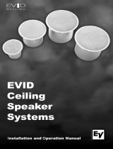
JBL Control 10 Series Owner's manual

Type
Owner's manual

JBL Control 10 Series ceiling loudspeakers deliver premium performance with innovative design and materials. Experience high-fidelity sound across a wide coverage area with the Control 12C/T's 3” driver, or enjoy wide bandwidth audio with the Control 14C/T's 4” woofer and ¾” tweeter. For extended bass response, choose the Control 16C/T with its 6.5” woofer or the Control 18C/T with its 8” woofer and 1” tweeter.

JBL Control 10 Series ceiling loudspeakers deliver premium performance with innovative design and materials. Experience high-fidelity sound across a wide coverage area with the Control 12C/T's 3” driver, or enjoy wide bandwidth audio with the Control 14C/T's 4” woofer and ¾” tweeter. For extended bass response, choose the Control 16C/T with its 6.5” woofer or the Control 18C/T with its 8” woofer and 1” tweeter.

1
Control 10 Series
Ceiling Loudspeakers
Owners Manual
& Installation Guide
Rev B
Control 12C/T, Control 14C/T, Control 16C/T, Control 18C/T
2
Table of Contents
Product Description .................................................... 2
Product Feature Identication ................................... 2
Installation Preparations ............................................. 3
Step-By-Step Installation and Wiring ....................... 3
Painting the Speaker .................................................... 7
Safety Agency Compliance ......................................... 7
Maintenance ................................................................. 8
Replacement Parts ....................................................... 8
Contacting JBL ............................................................. 8
Product Specications ................................................. 8
ank you for purchasing JBL Control Contractor ceiling
loudspeakers. Read through this manual to familiarize
yourself with the features, applications and precautions
before you use these products.
Product Descriptions
e JBL Control Contractor Control 10 Series ceiling
loudspeakers utilize innovative design and materials to
provide premium level performance from compact in-
ceiling speakers. Available in white or black (-BK).
CONTROL 12C/T – A 3” (75 mm) full-range driver to
provide high-delity full-range sound over an extremely
wide coverage area.
CONTROL 14C/T – A wide bandwidth ceiling speaker
containing a co-axially mounted 4” (100 mm) woofer and
¾” (19 mm) so-dome tweeter.
CONTROL 16C/T – A wide bandwidth, high sensitivity,
extended bass ceiling speaker containing a co-axially
mounted 6.5” (165 mm) woofer and ¾” (19 mm) so-
dome tweeter.
CONTROL 18C/T – A high-output, more narrow
coverage extended bass ceiling speaker containing a
co-axially mounted 8” (200 mm) woofer and 1” (25 mm)
so-dome tweeter.
(Control 14C/T Shown)
Product Feature Identication
Zinc-Plated
Steel Backcan
Tap Selector for
70V/100V taps, 8Ω
direct and OFF Loudspeaker
Driver
Attachment
Screws
Removeable
Locking Input
Connector
Strain Reliefs
(x2)
Seismic Tab
(secondary
support point)
Terminal Cover
Plate
Rotating
Mounting Tabs
(dog-ears)
Perforated
Press-In Grille
3
Installation Preparations
e entire installation can be accomplished, if necessary, with-
out requiring access above the ceiling. Bracketry for use with
either suspended ceilings or sheetrock ceilings is included. e
speaker is held securely in place via mounting ears which lock
into place. Inputs are attached to a removable locking con-
nector (included) which can be prewired before installing the
speaker for ultra-fast snap-on installation.
OPTIONAL PRE-INSTALLATION BRACKETS
IN MOST CASES, NO BRACKETS OTHER THAN THE
ONES INCLUDED WITH YOUR SPEAKER ARE REQUIRED.
Everything needed for most installations of these loudspeakers
is provided with your Control Contractor ceiling speaker.
However, when the speaker is being installed into a sheet rock
(typically gypsum board) ceiling, JBLs optional pre-installation
brackets can be installed before the sheetrock is installed. e
pre-installation bracket provides a bracket to which wiring can
be tied behind the sheetrock. It can function as a cutout tem-
plate when many cutouts are to be made in a production-line
style installation, and it secures the ceiling speaker to the
building structure. Two types of pre-installation brackets are
available from JBL Professional as optional accessories:
1) e optional NEW-CONSTRUCTION BRACKET is made
of at sheetmetal, with wings to attach to the building structure.
Holes are drilled for nails or screws at 16 inches (406 mm) and
24 inches (610 mm) on-center. Additional holes can be drilled
by the installer at other spacings up to a maximum of 24-3/4
inches (630 mm) apart. Sheet rock installs over the bracket, and
the bracket provides a template for blind cutout of the hole in
the sheet rock. e sheet rock is typically cut with a router-type
cutting tool, using the bracket ring as a cutout guide.
Figure 1:
Optional NC New-Construction Bracket
2) e optional PLASTER-RING BRACKET (or “mud ring”)
contains a circular oset, forming a edge guide for sheet rock
plastering. e bracket has wings that attach to the building
structure. Sheet rock is typically either precut or cut with a
rotary cutting tool using the outside of the plaster ring circle as
a guide. e sheet rock hole is then plastered (or “mudded”) up
to the ring to create a seamless cutout.
Figure 2:
Optional MR Plaster-Ring Bracket (“Mud Ring”)
Table 1: New Construction Brackets
Model
New
Construction
Bracket
Plaster-Ring
Bracket
Control 12C/T MTC-24NC MTC-24MR
Control 14C/T MTC-24NC MTC-24MR
Control 16C/T MTC-26NC MTC-26MR
Control 18C/T MTC-47NC MTC-47MR
USING INCLUDED C-BRACKET WITH
SHEET-ROCK
For most installations, the INCLUDED C-shaped backing plate
provides adequate reinforcement to the ceiling material, spread-
ing out the clamping force from the tab clamps.
CUTOUT SIZES
Table 2: Cutout Sizes
Model
Cutout Size
(diameter)
Control 12C/T 167 mm (6.6 in)
Control 14C/T 167 mm (6.6 in)
Control 16C/T 225 mm (8.8 in)
Control 18C/T 282 mm (11.1 in)
STEP-BY-STEP
INSTALLATION AND WIRING
e installation system has been designed so that the entire
installation can be accomplished from beneath the ceiling for
instances when access above the tile is not possible or practical.
However, in some cases it may be easier with removable ceiling
tiles to access from both the top and bottom of the ceiling tile
during various phases of the installation.
4
Step 1 – Cut the Hole. Cutout the circular hole to the cutout
hole size listed above. Pull the wiring through the cutout hole.
Figure 3:
Hole Cutout
Step 2 – Insert Backing Hardware rough the Hole. Pack-
aged with the speakers are two types of backing hardware – a
C-shaped backing-plate bracket and two tile rails.
Suspended Ceilings – Insert the C-plate through the hole
cut in the ceiling tile. Place the C-plate around the hole with
the tabs located as shown on Figure 4. Insert the tile rails
through the cut hole in the ceiling tile. Snap the two rails
into the two tabs in the C-plate and align the rails so that the
ends extend OVER the T-channel grid on the side of the tile.
Secure the rails onto the C-bracket tabs by inserting a screw
though each tab into the rail. is can all be accomplished
from below the ceiling tile, if necessary.
FOR SAFETY:
IMPORTANT TO USE BRACKETS
ALL included support brackets – C-plate and
tile rails -- MUST be used when installing into
suspended ceiling tiles.
Figure 4:
C-Bracket and Tile Rail Positioning on Ceiling Tile
Additional Suspended Ceiling Installation
Information
Tile Rails: e tile rails are designed to t either standard
24-inch wide tiles or 600-mm wide tiles. e tile rail piec-
es do NOT physically attach to the T-grid struts. Instead,
the inverted-V shape at the ends of the rails sit OVER
the T-grid strut. During normal operation, the rails are
supported by the edge of the tile. If the tile were to come
out or fall apart, the ends of the support rails are designed
to catch onto the T-grid, providing secure support to hold
the loudspeaker assembly in place.
Vibration Reduction: Loudspeakers can generate sub-
stantial vibration which can cause buzzing of the ceiling
materials or structure. Depending on the character of the
ceiling tile and structure, the installer might need to place
neoprene or other dampening material under the tile rails
or the edges of the tiles to eliminate rattles.
Cutout Placement: e tile rails are pre-punched with
attachment holes along their length. Placement is not
limited to the center of the tile as is the case with many
other tile rail support systems.
Non-Suspended Ceiling Types – e C-bracket can be
optionally used by itself to shore up the ceiling material and
to spread out the clamping force from the tab clamps. Insert
the C-plate through the cut hole in the ceiling and place it on
the back side of the hole before inserting the speaker.
Step 3 – Connect the Wiring to the Removable Locking
Connector – e connector is INCLUDED with the speaker.
Connect the wire by stripping the insulation back about 5 mm
(about 3/16 inch). Do NOT strip wires back any longer than
this. Insert the bare end of wire fully into the connector (not al-
lowing any bare wire outside of connector) and screw down the
hold-down screw until tight using a small atblade screwdriver.
Tighten any unused screws to avoid rattling from vibration.
Figure 5:
Connecting Wires to Removeable
Locking Connector
5
Guide to the Pins for Connection -- e removable locking
input connector contains 4 terminals, as marked on the con-
nector. e pin functions are listed on the label located on the
terminal cover plate.
Figure 6
Connecteor Pins
Pins 1 & 2 are the “+” and “-” inputs to the loudspeaker. Pins 1
& 2 are looped to pins 3 & 4, respectively (Pin 1 connects to Pin
3 and Pin 2 connects to Pin 4) inside the speaker. Pins 3 & 4 are
intended as loop-through connections to subsequent loud-
speakers. ere are two possible hookup schemes for connect-
ing subsequent speakers, determined by the desired result from
the circuit whenever this speaker’s connector gets disconnected
during troubleshooting:
Paralleling Input Terminals -- Connect the wire pair of the
subsequent speaker to pins 1 & 2 (in parallel with the input
wire pair). Whenever the connector is pulled out of the
speaker for troubleshooting, subsequent speakers will stay
connected. is can be useful during troubleshooting to
be able to disconnect a single loudspeaker at a time. In this
hookup scheme, no wires get connected to pins 3 & 4.
Figure 7:
Paralleling Input Terminals
Figure 8:
Parallel System Hookup Diagram
Using Loop-rough Terminals (Pins 3 & 4
) -- By connect-
ing the wire pair of the subsequent speaker to pins 3 & 4,
then all subsequent speakers will be disconnected when this
speaker’s connector is disconnected during troubleshooting,.
is can be useful as a way to isolate problems to a section
of the distributed line while leaving the wires attached to the
connector.
Figure 9:
Using Loop-Through Terminals
Figure 10:
Loop-Through System Hookup Diagram
Choose whichever hookup pattern accommodates your instal-
lation best.
Step 4 – Open the Strain Relief Fitting / Terminal
Cover
Figure 11:
Open the strain relief tting by loosening the two set screws in
the backcan, then loosen the two horizontal screws, and slide
open the sliding cover.
Loosen the screws holding the ttings sliding piece of the in-
put-terminal cover and slide the cover open.
Step 5 – Plug connector into connector socket in
the speakers terminal cup.
Figure 12:
Plug Connector into Connector Socket. Shown with a single
cable (left) or with two cables for input and loop-through (right)
From Amplier
or Previous
Speaker
To Subsequent
Speaker(s)
+ -
Power
Amplier
From Amplier
or Previous
Speaker
To Subsequent
Speaker(s)
To
Subsequent
Speaker(s)
+ -
Power
Amplier
+
--
+
+
-
To
Subsequent
Speaker(s)
6
Step 6 – Tighten the Strain Relief Fitting & Close
the Terminal Cover
Figure 13:
Tighten the Two Horizontal Screws to Slide and Tighten the
Strain Relief Fitting. Then Tighten the Two Set Screws into the
Backcan. (Shown with a single speaker cable)
Tightening onto Flexible or Hard Conduit – e supplied tting
accommodates up to 3/8 inch (9.5mm) exible conduit. Insert
the conduit into the strain relief tting. Tighten the sliding
Strain Relief Fitting.
Step 7 – Insert the Speaker Into the Ceiling and
Tighten.
Figure 14:
Inserting Speaker into Ceiling
(C-ring/tile-rail assembly is above the ceiling tile. Speaker
inserted through cutout in ceiling material. Diagram shown
without cable and ceiling tile for clarity)
Insert the speaker into the ceiling as far as it goes, until the front
bae rim touches the ceiling.
Turn the attachment screws to tighten the mounting tabs, by
using the following directions:
Figure 15:
Tightening Mounting Tabs
IMPORTANT -- For each attachment screw, FIRST turn ½ turn
COUNTER-CLOCKWISE to release the mounting tab from its
guide.
en tighten the mounting tabs by turning the screw CLOCK-
WISE until tight. e rst ¼ clockwise turn rotates the attach-
ment tabs outward and the remaining turns tighten the tabs
down onto the back of the ceiling surface. DO NOT OVER-
TIGHTEN.
A tab is provided on the back of each speaker for connection
to a independent secondary support point. Some construc-
tion codes require using this secondary support point, which
requires connecting a support line to a separate secure support
point. Consult construction codes in your region.
IMPORTANT -- Control Contractor ceiling speakers can gen-
erate substantial vibration . Using the seismic tab as a secondary
support point is highly recommended in case the ceiling tile
or structure breaks. In some areas, using the seismic tab as a
secondary support point is required by code.
Step 8 Adjust Tap Selector e tap selector rotary
switch is located on the front bae. Adjust the tap setting
before applying power to the speaker and before inserting the
grille. From the OFF position, turn the selector counter-clock-
wise to set to the 8Ω (low impedance) nominal setting (see
spec sheet for more precise impedance information) or turn the
selector clockwise to set to the various 70V and 100V distribut-
ed system tap settings.
7
Figure 16:
Tap Selector
(Shown: Control 14C/T. Tap ratings on the
other models differ from these gures.)
Step 9 – Insert the Grille Consider which direction the
logo is facing and press the grille into place until the front of the
grille is ush with the rim. It is oen easiest to press in various
places around the perimeter of the grille. Make sure grille is
securely seated to prevent it from vibrating loose and falling.
Removing the Grille -- e grille presents a tight t in order
to make sure that it wont fall out, even with high vibrations
that can be produced by these speakers. If you need to
remove the grille, it is easiest to do so by inserting 2 pointed
objects (such as push pins) into 2 nearby holes in the grille,
presenting slow even pressure to pull down on the grille until
that section of the grille comes out approximately 6 mm (1/4
inch) . Work your way around the grille, loosening a section
at a time until the grille comes out.
Painting the Speaker
e speaker’s textured white nish complements most decor
and does not need further nishing. Where the interior design
requires it, these speakers are easy to paint.
e rim can be painted before installation or in cases where the
rim needs to be nished along with the ceiling, the speaker rim
can be painted aer attaching into the ceiling.
Type of Paint – e speaker’s ABS rim accepts almost any type
of latex or oil based paint. Two coats are recommended.
Painting Process – For best results, the following procedure is
recommended:
• Clean the rim and grille with a light solvent such as mineral
spirits by rubbing the item with a lightly dampened cloth. Do
not, however, use abrasives such as sandpaper or steel wool. Nor
should you use gasoline, kerosene, acetone, MEK, paint thinner,
harsh detergents or other chemicals. Use of these cleaners may
result in permanent damage to the enclosure.
• Aer cleaning, apply two or more thin coats of either latex
or oil-based paints. Latex paint will adhere best if an oil-based
primer is used rst. Application can be made by rolling, brush-
ing or spraying.
Painting the Speaker Along With the Ceiling – Insert the clear
plastic paint shield into the front of the speaker to mask the
drivers and internal bae, paint the speaker, then remove the
shield.
Painting the Grille – Painting the grille requires removal of the
logo prior to painting (the logo should be stuck back onto the
grille aer painting, making sure it is located in the exact center
of the grille).
e backing to the grille is glued in place so that it can’t interfere
with the movement of the woofer cone. Leave the grille backing
in place. Spray the grille lightly using thinned paint. Make
sure the spray is light enough that when the grille is held up to
the light, you can still see light through the grille holes (which
means that sound can also get through). Spray only the front of
the grille, not the back. Rolling or brushing the paint is discour-
aged because the mesh and/or backing may become clogged
with paint and poor sound quality may result, however using a
very short-napped roller can be made to work.
Safety Agency Compliance
S7232
LISTED
15CM
Signaling Speaker
UL-2043 Fire Tests for Heat and Visible Smoke Release for
Discrete Products and their Accessories Installed in Air Han-
dling Spaces, NFPA-70 National Electric Code 1996, Article
300-22(C), and NFPA-90A Installation of Air Conditioning and
Ventilation Systems, Section 2-3.10.1 (a), Exception 3. List-
ed UL1480-6 Speakers for Fire Protective Signaling Systems.
SUITABLE FOR USE IN AIR HANDLING SPACES.
ese products are in compliance with the EMC Directive
89/336/EEC and Article 10 (1) of the directive. In compliance
with Technical Regulations EN50081-1 and EN50082-1. For a
copy of the model-specic CE Declaration of Conformity, con-
tact JBL at the address listed at the end of this manual.
8
Maintenance
No maintenance is required when installed in accordance with
installation and wiring guidelines described in this manual.
Replacement Parts
ere are no user serviceable parts inside these speakers.
Refer servicing to an authorized JBL Service Center. For
the name of an authorized Service Center in your area,
contact JBL Professional at the address listed below.
Warranty & Contacting JBL
ese products are designed and backed by JBL Professional,
the world leader in sound reinforcement. For complete JBL
warranty information, to order replacement parts or to ask for
clarications to this manual, contact JBL Professional:
WITHIN THE UNITED STATES: Contact the Applications
Dept, JBL Professional, PO Box 2200, 8500 Balboa Blvd,
Northridge CA 91329 USA. In the USA you may call Mon-
day through Fiday 8:00 am to 5:00 pm Pacic Coast Time
(818) 894-8850.
IN OTHER AREAS THROUGHOUT THE WORLD: Con-
tact the JBL Professional Distributor in your country.
A list of JBL Professional Distributors and U.S. Service
Centers can be obtained from the JBL Professional website at
www.jblpro.com.
---------------------------------------------------------------------
1 Half-space (flush mounted in ceiling)
2 Continuous Pink Noise Rating is IEC-shaped pink noise with a 6 dB crest
factor for 100 hours continuously. Continuous Program Power is a
conservative expression of the systems ability tohandle normal speech and
music program material, and is defined as 3 dB above the Continuous Pink
Noise Rating.
3 Half-space (in ceiling) average 1 kHz to 16 kHz.
Product Specications
See product specication sheets for complete specication
listings.
Control 12C/T
Components: 76 mm (3 in) full-range driver
Frequency Range1: 68 Hz - 17 kHz
Power Capacity (low-Z): 40 W Cont. Program
20 W Cont. Pink Noise
Sensitivity2: 84 dB
Coverage3: 130˚
Max. SPL: 97 dB @ 1m ave., 103 dB peak
Nominal Impedance: 8 ohms (in direct/bypass 8Ω setting)
Transformer Taps: 15W, 7.5W, 3.8W @ 70V & 100V;
plus 1.9W @ 70V
Control 14C/T
Components: 100 mm (4 in) LF driver
19 mm (3/4 in) HF driver
Frequency Range1: 74 Hz - 20 kHz
Power Capacity (low-Z): 60 W Cont. Program
30 W Cont. Pink Noise
Sensitivity2: 87 dB
Coverage3: 120˚
Max. SPL: 102 dB @ 1m ave., 108 dB peak
Nominal Impedance: 8 ohms (in direct/bypass 8Ω setting)
Transformer Taps: 25W, 12.5W, 6.3W @ 70V & 100V;
plus 3.2W @ 70V
Control 16C/T
Components: 165 mm (6.5 in) LF driver;
19 mm (3/4 in) HF driver
Frequency Range1: 62 Hz - 20 kHz
Power Capacity (low-Z): 100 W Cont. Program
50 W Cont. Pink Noise
Sensitivity2: 91 dB
Coverage3: 110˚
Max. SPL: 108 dB @ 1m ave., 116 dB peak
Nominal Impedance: 8 ohms (in direct/bypass 8Ω setting)
Transformer Taps: 30W, 15W, 7.5W @ 70V & 100V;
plus 3.8W @ 70V
Control 18C/T
Components: 200 mm (8 in) LF driver;
25 mm (1 in) HF driver
Frequency Range1: 58 Hz - 20 kHz
Power Capacity (low-Z): 180 W Cont. Program
90 W Cont. Pink Noise
Sensitivity2: 92 dB
Coverage3: 90˚
Max. SPL: 112 dB @ 1m ave., 118 dB peak
Nominal Impedance: 8 ohms (in direct/bypass 8Ω setting)
Transformer Taps: 60W, 30W, 15W @ 70V & 100V;
plus 7.5W @ 70V
C10 MANUAL
Revision B
JBL Professional
8500 Balboa Blvd, P.O. Box 2200
Northridge, CA 91329 U.S.A.
9
  • Page 1 1
  • Page 2 2
  • Page 3 3
  • Page 4 4
  • Page 5 5
  • Page 6 6
  • Page 7 7
  • Page 8 8
  • Page 9 9

JBL Control 10 Series Owner's manual

Type
Owner's manual

JBL Control 10 Series ceiling loudspeakers deliver premium performance with innovative design and materials. Experience high-fidelity sound across a wide coverage area with the Control 12C/T's 3” driver, or enjoy wide bandwidth audio with the Control 14C/T's 4” woofer and ¾” tweeter. For extended bass response, choose the Control 16C/T with its 6.5” woofer or the Control 18C/T with its 8” woofer and 1” tweeter.

Ask a question and I''ll find the answer in the document

Finding information in a document is now easier with AI