Electro-Voice EVID12.1 User manual

Category
Soundbar speakers
Type
User manual
Installation and Operation Manual
EVID
Ceiling
Speaker
Systems
ii EVID™ Ceiling Series Installation and Operation Manual
Table of Contents . . . . . . . . . . . . . . . . . . . ii
Welcome . . . . . . . . . . . . . . . . . . . . . . . . . . 1
Important Features . . . . . . . . . . . . . . . . . . 1
Model Summary . . . . . . . . . . . . . . . . . . . . 2
Packing List. . . . . . . . . . . . . . . . . . . . . . . . 2
Product Feature Identification. . . . . . . . . . 3
Installation and Wiring . . . . . . . . . . . . . . . 4
Step 1 — Cut the Hole . . . . . . . . . . . . . . 5
Step 2 — Install C-Ring
and/or Tile Rails . . . . . . . . . . . . . . . . 5
Step 3 — Attach Wiring to the
Terminal Connector . . . . . . . . . . . . . 5
Step 4 — Secure the Cable to the
Speaker . . . . . . . . . . . . . . . . . . . . . . . 6
Step 5 — Mount the Speaker into the
Ceiling. . . . . . . . . . . . . . . . . . . . . . . . 7
Step 6 — Connect an Auxiliary
Support Line . . . . . . . . . . . . . . . . . . . 8
Step 7 — Adjust Tap Selector . . . . . . . . . 8
Step 8 — Insert the Grille. . . . . . . . . . . . 8
Appendix A — Painting the Speaker. . . . . . 9
Appendix B — System Design Guide . . . . 10
Selecting and Positioning Ceiling
Loudspeakers. . . . . . . . . . . . . . . . . . 10
Ceiling Systems: Size vs. Coverage. . . . 10
Use of Subwoofers. . . . . . . . . . . . . . . . 11
Appendix C — Troubleshooting Table . . . 12
Appendix D — Warranty . . . . . . . . . . . . . 13
Exclusions and Limitations . . . . . . . . . 13
Appendix E — Product Specifications . . . 14
Table of Contents
Welcome
Thank you for purchasing EVID™ Ceiling
Series loudspeakers. Read through this man-
ual to familiarize yourself with features,
applications, and precautions before you use
these products.
EVID Ceiling Series loudspeakers use
innovative design and materials to provide
premium-level performance in a f lush-mount
ceiling format. Four models comprise the
EVID Ceiling Series: the C4.2 with a 4-inch
LF driver and a .75-inch, titanium-coated
tweeter with waveguide; the C8.2 with an
8-inch LF driver and a 1-inch titanium-coated
tweeter with waveguide; the C8.2HC with a
fully waveguide-loaded 8-inch LF driver and
a 1-inch titanium coated tweeter; and the
EVID 10.1, a true ceiling-mounted subwoofer
designed to augment and extend the full-
range model’s low-frequency response.
Important Features
Matches acoustically to the EVID surface-
mount speaker line
Model for model, has superior perform-
ance to competing brands
Comes with both 70V/100V or 8-ohm
operation standard on every model
Includes all installation accessories
commonly needed for most jobs
1EVID™ Ceiling Series Installation and Operation Manual
Welcome/Important Features
EVID™ C4.2
Perfect for conventional rooms. It has excel-
lent bandwidth in an esthetically very unob-
trusive installation profile. Its compact
design fits in tight areas. Its 4-inch woofer
and waveguide-coupled, titanium-coated
dome tweeter give smooth, wide frequency
response. The enclosure is ported and tuned
to provide surprising bass response in such
a compact package. Features an easy 3-point
mounting system for quick installations.
EVID C8.2
The C8.2 has a specially tuned enclosure and 8-
inch woofer to provide amazing bass response.
The 1-inch waveguide-coupled tweeter give
smooth controlled coverage out to 20 kHz.
Perfect for installations where a flush-mount
design is desired but demand for high-quality
audio exists. Features a 4-point mounting sys-
tem to make installations fast and easy.
EVID™ C8.2LP
The C8.2LP is the same as the C8.2 but in a
low-profile installation package. Ideal for
tight ceiling spaces.
EVID™ C8.2HC
The EVID C8.2HC is ideal for high ceilings and
reverberant “problem” rooms. Its exclusive
ported, waveguide-coupled, 8-inch driver pro-
vides excellent intelligibility and definition.
The 8.2HC’s patent-pending design provides
great coverage control throughout the voice
range and above. No other ceiling speaker sys-
tem provides the combination of excellent pat-
tern control, wide bandwidth, high power han-
dling, and compact design like the C8.2HC.
EVID™ C10.1
The C10.1 packs a 10-inch subwoofer in a
tuned high performance enclosure to give
amazing low frequency performance down
to 45Hz! It is one of the few quick-mount
ceiling TRUE subwoofers available. Flexible
installation and powerful low-end perform-
ance make it the ideal mate to any EVID ceil-
ing model.
Packing List (Figure 1)
Figure Quantity Part
A 2 Speaker system
B 4 Tile rails
C 2 C-ring support
D 2 Grille
E 1 Owner’s manual
F 4 Support ring screws
G 2 Terminal connector
H 1 Service center card
I 1 Cutout template
J 2 Paint Shield
2 EVID™ Ceiling Series Installation and Operation Manual
Model Summary/Packing List
A (x2)
E
G (x2)
C (x2)
H
D (x2)
F (x4)
B (x4)
I
J (x2)
Figure 1: EVID packing list
EVID™ Ceiling Series Systems (sold in pairs)
Model Part No. Description
C4.2 301258000 4" coaxial speaker with horn-loaded, Ti-coated tweeter
C8.2 301261000 8" coaxial speaker with horn-loaded, Ti-coated tweeter
C8.2LP 301318000 Same as C8.2 above except with low-profile backcan
C8.2HC 301262000 8" waveguide-coupled* coaxial speaker with horn-loaded, Ti-coated tweeter
C10.1 301263000 10" High performance subwoofer
*
Patent pending
EVID Series Ceiling Mount Speaker Accessories
Model Part No. Description
RR-42 301305000 Rough-in plate for new construction involving the EVID C4.2
(package of 4)
RR-82 301306000 Rough-in plate for new construction involving the EVID C8.2
and C8.2LP (package of 4)
RR-810 301307000 Rough-in plate for new construction involving the EVID C8.2HC
and C10.1 (package of 4)
RPK-42 301308000 Rough-in package for new construction involving the C4.2 speaker
only (package of 2)
RPK-82 301309000 Rough-in package for new construction involving the C8.2
and C8.2LP speaker only (package of 2)
RPK-810 301310000 Rough-in package for new construction involving the C8.2HC
and C10.1 speaker only (package of 2)
Product Feature Identification
3EVID™ Ceiling Series Installation and Operation Manual
Product Feature Identification
Grille safety tether
Grille
Strain relief fitting
Seismic tab
(auxiliary support ring)
Removable input terminal connector
Rotating mounting tabs
Terminal cover plate
Figure 3: Top of speaker
Steel
backcan
Mounting
screws
Tap
selector
Grille safety
tether hole
Figure 2: Bottom of speaker
The EVID mounting system has been
designed so that, if necessary, the installation
can be done from beneath the ceiling. In
some cases with a suspended ceiling grid,
however, it may be easier to access from both
the top and bottom of the ceiling tile during
the installation process. Typical installation
hardware needed for either suspended ceil-
ings or sheetrock ceilings is included. The
ceiling speaker assembly is held in place by
mounting tabs that securely grip the ceiling
material. Input wiring is attached to a remov-
able terminal block connector that can be
pre-wired if necessary before speaker installa-
tion to speed up the installation process.
INSTALLATION NOTE: USE OF OPTIONAL
ROUGH-IN ACCESSORIES
For most installations, no additional hard-
ware is needed. However, a two-step installa-
tion procedure that is sometimes used for
installation into sheetrock ceilings can be
made easier by the use of the optional RR
and RPK series of rough-in accessories
before the ceiling material is installed. The
rough-in accessories provide a cutout guide
when many holes are to be made in a pro-
duction-line style installation and to ensure
the speakers are positioned correctly as the
holes are cut in the sheetrock. Depending on
the requirements, two types of rough-in
accessories are available.
RR Series Mounting Plates
RR series plates are made of flat sheet metal
with holes to attach to the joists or trusses of a
building structure. The holes are drilled for
nails or screws at 16 inches (406 mm), 20
inches (508 mm) and 24 inches (610 mm) on-
center. The installer can drill other holes as
needed up to a maximum of 24-3/4 inches
(630 mm) apart. The sheetrock installs over
the plate, and the plate provides a template for
a blind cutout of the hole in the sheet rock.
The ceiling material is generally cut with a
router-type cutting tool, using the plate ring as
a cutout guide. The mounting plate is illustrat-
ed in Figure 4.
RPK Series Kits
The RPK series rough-in kit contains a RR
series plate with a standard 2 gang electrical
box mounted on the top with an attached
short length of flexible conduit which con-
nects to the ceiling speaker conduit clamp on
the speaker’s rear terminal cover. This accesso-
ry allows for rigid conduit to be run to the box
on the rough-in plate before the speaker or
any sheetrock is installed. After the sheetrock
is installed the speaker can be wired up and
mounted all from below the ceiling. The RPK
mount system is shown in Figure 5.
INSTALLATION NOTE: CONTROLLING
VIBRATION
Because of their high performance, EVID
ceiling loudspeakers can generate substantial
vibration, which can cause buzzing in loose
sections of the ceiling structure. Depending
on the character of the ceiling tile and relat-
ed components, dampening material may
need to be used under the tile rails or the
edges of the tiles to eliminate rattles.
4 EVID™ Ceiling Series Installation and Operation Manual
Installation and Wiring
Figure 4: Speaker mounting plate
Figure 5: RPK mounting system
Step 1: Cut the Hole (Figure 6)
For suspended tile or sheetrock ceilings, cut
out the hole either by tracing the cardboard
template or with a circular cutter set to the
appropriate cutout size. If the wire has been
pre-installed, pull the wiring through the
cutout hole.
Step 2: Install C-Ring and/or Tile
Rails (Figure 7)
All EVID speakers come packaged with two
types of backing hardware: a C-ring and two
tile rails.
For suspended ceiling installations, insert
the C-ring through the hole cut in the ceiling
tile. Place the C-ring around the hole with
the tabs located as shown in Figure 7. Insert
the tile rails through the cut hole in the ceil-
ing tile. Snap the two rails into the two tabs
in the C-ring and align the rails so that the
ends extend OVER the T-channel grid on the
side of the tile. Secure the rails onto the C-
ring tabs by inserting a screw though each
tab into the rail, as shown in Figure 7.
INSTALLATION NOTE: TILE RAILS AND
C-RING
Each speaker comes with two tile rails which
are designed to fit either standard 24-inch-
wide or 600-mm-wide tiles. It is important to
note that the tile rail pieces do not actually
attach to the T-grid struts. The ends of the
rails sit OVER the T-grid strut. Normally, the
tile supports the rails. The tile rails are pre-
punched at regular intervals with holes along
their length. This allows the C-ring to be posi-
tioned at any point along the rail. If the tile
comes out or falls apart, the ends of the sup-
port rails fall onto the T-grid, which prevents
the speaker assembly from falling.
Always use all included support hardware
when installing into suspended ceiling tiles
to make sure the installation is secure.
For sheetrock ceiling installations, the C-
ring should be used by itself to reinforce the
ceiling material and to spread out the pres-
sure from the speaker hold-down tabs.
Guide the C-ring through the cut hole in the
ceiling, and place it on the back side of the
hole before inserting the speaker.
Step 3: Attach Wiring to the
Terminal Connector (Figure 8)
Insert the bare end of wire into the appro-
priate connector terminals as described
below and screw down the hold-down
screw until tight, using a small screwdriver.
5EVID™ Ceiling Series Installation and Operation Manual
Installation and Wiring
Figure 6: Cut ceiling hole
Figure 7: Secure rails to C-Ring
Screwdriver
Figure 8: Tighten with screwdriver
INSTALLATION NOTE: CONNECTOR
WIRING GUIDELINES
The input connector’s 4 terminals are num-
bered and marked on the connector. Pins 1 and
2 are positive (+); pins 3 and 4 are negative (–).
(Pin 1 is connected to Pin 2 and Pin 3 is con-
nected to Pin 4 inside the speaker.) Pins 1 and
4 are used as daisy-chain connections to other
loudspeakers. Two possible layouts for wiring a
group of speakers are described below.
1. Wiring in parallel. Connect the wire
pair of the subsequent speaker to pins 2 and
3. When one input connector is removed,
subsequent speakers will remain connected.
See Figure 9.
2. Daisy-chaining. Connect the wire pair
of the subsequent speaker to pins 1 and 4.
When one input connector is removed, sub-
sequent speakers will also be disconnected.
See Figure 10.
INSTALLATION NOTE: SUBWOOFER
POLARITY
When adding a subwoofer, be sure to observe
the correct polarity. The C10.1 subwoofer has
been designed for optimum performance
when used with the C4.2. In order to maxi-
mize the low frequency output when used
with the C8.2, C8.2LP or C8.2HC, the polarity
of the C10.1 subwoofer should be reversed.
See Figures 11 and 12.
When all wiring has been completed to the
connector, plug the connector into the socket
in the speaker’s terminal cup. See Figure 13.
Tighten all screws to eliminate vibration.
Step 4: Secure the Cable to the
Speaker (Figure 14)
Fully loosen the horizontal screw shown in
Figure 13, then the strain relief screws. Run
the wires through the opening in the fitting
and plug the input connector into the speak-
er’s terminal block. Then tighten the strain
relief fitting as follows:
6 EVID™ Ceiling Series Installation and Operation Manual
Installation and Wiring
From amplifier or
previous speaker
To next speaker
Figure 10: Daisy-chain wiring
From amplifier or
previous speaker
To next speaker
Figure 9: Parallel wiring
Hold-down
screw
Input connector
Terminal
block
Strain
relief
screws
Horizontal
screw
Figure 13: Plug connector into socket
C10.1 Subwoofer C4.2 Loudspeaker
Figure 11: Subwoofer polarity with C4.2
C10.1 Subwoofer
C8.2/C8.2HC/C8.2LP
Loudspeaker
Figure 12: Subwoofer polarity with
C8.2/C8.2HC/C8.2LP
1. If plenum cable is used, slide the wiring
through the strain relief fitting on the termi-
nal cover plate (Figure 14). Hold the strain
relief fittings tight around the cable. Tighten
the strain relief screws first, then the hori-
zontal screw. In the cases of insulated
speaker wire and plenum cable, it is often
possible to provide acceptable strain relief
force by simply tightening the strain relief
screws onto the terminal cover plate.
2. If the installation used f lexible (BX) or rigid
(EMT) conduit, an alternate conduit fitting
can be used. See Installation Note and
Figure 15 below.
INSTALLATION NOTE: ALTERNATE
CONDUIT FITTINGS
Some cases require alternate fittings, many of
which are available through most electrical
suppliers. Simply remove the existing fitting
by unscrewing the two hold-down screws,
exposing a 7/8-inch (22 mm) knockout hole.
Then install the alternate fitting. Make sure to
always use a listed fitting in accordance with
your area’s building codes and regulations.
INSTALLATION NOTE: CEILING TILE
CAUTION
When mounting the units into 2'×2' or 2'×4'
suspended ceiling tiles, DO NOT install them
in lightweight fibreglass-type tiles without
full secondary support for the speaker as
noted in Step 6. Such tiles are not designed
to support any substantial weight. Speaker
installation without secondary support will
cause the tile to sag and distort, even with
the tile bridge installed. The secondary sup-
port line at the rear of the speaker MUST be
strung taut in these situations and MUST
remove most of the force of the speaker on
the tile to ensure that the speaker does not
deform the tile.
Step 5: Mount the Speaker Into
the Ceiling (Figure 16)
Push the speaker into
the ceiling hole until
the front baffle rim is
flush with the ceiling.
Tighten the mounting
tabs by turning the
screw clockwise until
the speaker is secure.
Please note that the
first clockwise quar-
ter-turn rotates the
attachment tabs out-
ward. The remaining
turns tighten the tabs
down onto the back
of the ceiling surface
(see Figure 17).
7EVID™ Ceiling Series Installation and Operation Manual
Installation and Wiring
Figure 14: Secure cable through fitting
Figure 15: Alternate conduit fitting
Figure 16: Mount
speaker into ceiling
Figure 17: Tighten mounting tabs
INSTALLATION NOTE: MOUNTING TABS
For each attachment screw, first turn one
half-turn counterclockwise to release the
mounting tab from its guide.
Step 6: Connect an Auxiliary
Support Line (Figure 18)
Note the support ring on the back of the
speaker. The ring allows for connection to a
independent and secure anchor point.
Construction codes often require the use of
this secondary support point.
Step 7: Adjust Tap Selector
(Figure 19)
The tap selector switch is located on the
front baff le. Adjust the speaker to the appro-
priate tap setting before installing the grille.
In some 70V/100V constant voltage installa-
tions it is advisable to leave the grilles off if
final speaker audio level balance adjust-
ments are to be made later. After the levels
are adjusted the grilles can then be installed.
EVID™ C4.2, C8.2 and C8.2LP
In addition to the 8-ohm setting, the power taps
are 30 W, 15 W, 7.5 W, and 3.7 W at both 70.7V
and 100V, with a 1.8 W tap for 70.7V only.
EVID™ C8.2HC and C10.1
In addition to the 8-ohm setting, the power
taps are 60 W, 30 W, and 15 W at both 70.7V
and 100V, with a 7.5 W tap for 70.7V only.
Step 8: Attach the Grille (Figure 20)
INSTALLATION NOTE:
GRILLE SAFETY FEATURE
EVID grilles features a unique safety tether
to prevent the grille from falling if the grille
is removed or comes loose after installation.
First, install the grille’s safety tether by
pushing the grille fastener into the hole in
the front of the baff le (see Figure 20).
Second, press the grille into place until the
front of the grille is flush with the rim of
the baffle. Make sure the grille is securely
seated to prevent it from vibrating loose.
If you need to remove the grille, the easiest
way is to insert two bent paper clips or other
pointed objects into holes in the grille, then
apply slow even pressure to pull down on the
grille until that section of the grille comes out
slightly. Continue the same procedure around
the perimeter of the grille, loosening a por-
tion at a time until the grille is removed.
8 EVID™ Ceiling Series Installation and Operation Manual
Installation and Wiring
Figure 18: Attach auxiliary support line
Figure 19: Adjust tap selector (left:
C4.2/C8.2/C8.2LP; right: C10.1/C8.2HC)
1
2
Figure 20: Attach the grille
If the speaker is installed in an area where
the interior design requires a color match,
these speakers are simple to paint. The
speakers can accommodate almost any type
of latex or oil-based paint. The bezel/rim
can be painted before installation or after
mounting into the ceiling.
Painting Process
Clean the rim and grille with mineral spirits
or other light solvent. Do not use harsh sol-
vents such as gasoline, kerosene, acetone, or
other chemicals. If you use these cleaners
you may permanently damage the enclosure.
Also, don’t use abrasives products such as
sandpaper or steel wool.
Either by rolling or spraying, apply two or
more thin coats of paint. If you are spraying,
hold the spray can at the angles shown in
Figure 21.
If you are painting the grille also, you
must first remove the internal grille cloth.
Spray painting is strongly recommended. If
the grille is rolled or brush painted, the
grille may become clogged with paint and
the sound quality will suffer. After the paint
has dried, replace the internal grille cloth.
If you wish to paint the speaker along
with the ceiling after installation, insert a
plastic or cardboard paint shield into the
front of the speaker to mask the drivers and
internal baffle, paint the speaker, then
remove the shield.
9EVID™ Ceiling Series Installation and Operation Manual
Appendix A — Painting the Speaker
45˚ 45˚
180˚
180˚
Baffle
Can
(do not
paint)
Figure 21: Spray-painting angles
Selecting and Positioning
Ceiling Loudspeakers
Several key criteria determine the type and
quantity of ceiling speakers to employ in a
job. Specific EVID™ Ceiling Series models
accommodate each job, depending on how
these criteria are specified.
Room size
Coverage density desired
Coverage angle specification of the speaker
Ceiling height
Audio program material being played
The information below, and the free design
program downloadable from www.electro-
voice.com (under downloads/speakers), will
help you optimize your EVID design.
In the traditional approach to overhead-
distributed systems, loudspeakers are placed
in a grid whose dimensions are dictated by
the room height and the directivity of the
speaker elements. Two basic placement pat-
terns prevail: square spacing and hexagonal
(or crisscross) spacing. See Figure 22.
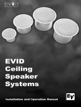
In addition to the spacing pattern, the
designer must choose between three cover-
age density types, designated respectively
as edge-to-edge, minimum overlap and cen-
ter-to-center. The greater the overlap, the
more uniform the coverage. The illustration
below shows these various layout patterns.
Ceiling Systems: Size vs. Coverage
In the past, system designers usually specified
8-inch cone loudspeakers for distributed over-
head systems, at least in part because they rep-
resented the traditional choice. EVID systems,
however, allow for far more f lexible options.
In many cases, you can achieve excellent
results — at a significant savings — by using 4-
inch transducers. This is especially true in jobs
that do not require extended low-end
response or high SPL levels. 4-inch transduc-
ers, such as those used in the C4.2, offer wider
dispersion to allow for fewer speakers to be
employed in the job. For example, due to its
smaller cone diameter, the C4.2 exhibits signif-
icantly wider dispersion (130 degrees) than
the C8.2 (110 degrees) at the -6 dB points.
The effect of this characteristic on an over-
head system is indicated in Figure 23. In
replacement applications where existing
speaker positions are used, the C4.2 (shown in
angle A) offers greater overlap and, thus, more
uniform coverage than an older conventional
8-inch unit (shown in angle B). When specify-
ing a new system, you can take advantage of
the C4.2’s wider dispersion to decrease the
number of speakers required to cover a given
area. This will result in even greater savings.
Of course, the C4.2 is somewhat less sensi-
tive than the 8-inch C8.2. The difference is
–5 dB. The C4.2 will also have slightly
reduced low-frequency capabilities below 65
Hz. However, neither of these factors is a sig-
nificant problem in many distributed systems.
The C4.2 is conservatively rated to handle 80
watts of continuous power equal to or greater
than most other brands of 8-inch units, so its
continuous SPL output will be more than ade-
quate. Moreover, its low-frequency output
can easily be augmented with the addition of
the C10.1 subwoofer. For these reasons, the
C4.2 represents a great way for you to pro-
vide good audio coverage while maintaining
a competitive edge in price quotes in installa-
10 EVID™ Ceiling Series Installation and Operation Manual
Appendix B — System Design Guide
Grid Edge-to-edge Minimum
overlap
Center-to-
center
Hexagonal
Square
Figure 22: Coverage patterns
Ceiling
A
B
A
B
Figure 23: Size vs. coverage
tions that do not need the extended perform-
ance of the larger models.
Reverberant Rooms
and High Ceilings
Situations arise, however, in which con-
trolled coverage is more desirable than
broad dispersion. Very large live spaces
such as gymnasiums, convention centers,
shopping mall atriums, and the like all ben-
efit from more controlled sound projection.
In such installations, the EVID 8.2HC is the
best choice. Its 75-degree coverage pattern
above 1kHz provides more intelligibility in
large, acoustically live spaces. It also has a
high 93dB sensitivity rating for optimum
efficiency.
SPL Requirements: How Loud?
The EVID C8.2 is a great speaker to use
when higher SPL is required. The fidelity
and bandwidth of the unit is substantial and
is ideal for applications requiring high quali-
ty foreground music reproduction. The C8.2
has substantial low frequency energy down
below 60Hz. This is more than sufficient for
most applications.
Layout: How Many?
The chart below shows the effective cover-
age diameter of the EVID models assuming a
4-foot listening plane height. Using these fig-
ures you can lay out a coverage pattern for
the job after deciding the overlap criteria
described earlier on page 10.
Coverage Diameter by Ceiling Height
Model 8' 12' 20' 24'
C4.2 17' 34' 68' 85'
C8.2 11.5' 23' 45' 57'
C8.2HC 6.5' 12' 24' 30'
C10.1 180° coverage
Use of Subwoofers
The C10.1 subwoofer can add considerable
low-frequency performance to any EVID
installation. It is important to note that the
C10.1 subwoofer depends on the ceiling
and walls to properly load itself and to rein-
force its bass output. Correct positioning is
important to get maximum impact.
In smaller rooms when a single C10.1 is
used, a center or near-center position is
best. This gives the most even coverage. For
larger rooms where more than one C10.1
are employed, the added effect of the
room’s walls can be used. In such a space,
position the subwoofers evenly throughout
the room and a few feet from the wall or
corners. The added loading of the walls will
enhance the response in these larger areas.
11EVID™ Ceiling Series Installation and Operation Manual
Appendix B — System Design Guide
Troubleshooting Table
Problem Possible Causes Action
No output Amplifier Make sure the amplifier channel is being fed an input
signal (preferably via a “signal input” indicator on the
amp).
Check that the amplifier channel’s volume is turned up.
Connect the speaker and cable, which had no output
to another amplifier channel, making sure an input
signal is fed to the new amp channel. If you then get
output, the problem was the amplifier channel. If not,
then the problem may be in the cable or speaker.
Speaker cable(s) Replace the cable(s) connecting the loudspeaker
system and amplifier.
Questionable or Faulty connection Check all cabling for proper connector contact. A bad
intermittent out- connection can result in intermittent contact or
put such as dramatically increased resistance, which in turn can
crackling cause reduced output or noises unrelated to the signal.
Improper power Check the power tap setting under the speaker grille to
tap setting ensure the setting is appropriate for the installation and
amplifier chosen.
Constant noise A faulty electronic Since loudspeakers cannot generate these sounds by
such as buzzing, device in the themselves, you may have a faulty electronic device in
hissing, or signal chain the signal chain.
humming
Poor system Check and correct the system grounding, as required.
grounding
Poor low- Out-of-polarity When two speakers are hooked up out of polarity (out
frequency hookup between of phase), the low frequencies cancel each other out.
output multiple speakers Try reversing the polarity of one of the speakers either
by turning around a dual-banana plug at the amplifier
or by reversing the tip/sleeve leads on the jack.
Whichever condition results in greater low-frequency
output is the in-polarity condition.
If none of the suggestions below solves your problem, contact your nearest EV
©
service center
or EV distributor.
12 EVID™ Ceiling Series Installation and Operation Manual
Appendix C — Troubleshooting Table
Uniform Limited Warranty
Electro-Voice
®
speakers and speaker systems
are guaranteed against malfunction due to
defects in materials or workmanship for a
period of five (5) years from the date of orig-
inal purchase. The Limited Warranty does
not apply to burned voice coils or malfunc-
tions such as cone and/or coil damage result-
ing from improperly mounted or installed
enclosures. If a covered malfunction occurs
during the warranty period, the product
will be repaired or replaced (at our discre-
tion) without charge. The product will be
returned to the customer prepaid. Additional
details are included in the Uniform Limited
Warranty statement.
Exclusions and Limitations
The Limited Warranty does not apply to: (a)
exterior finish or appearance; (b) certain
specific items described in the individual
product-line statements below, or in the
individual product sheet or owner’s manual;
(c) malfunction resulting from use or opera-
tion of the product other than as specified
in the product data sheet or owner’s manu-
al; (d) malfunction resulting from misuse or
abuse of the product; or (e) malfunction
occurring at any time after repairs have
been made to the product by anyone other
than Electro-Voice
®
Service or any of its
authorized representatives.
Obtaining Warranty Service
To obtain warranty service, a customer must
deliver the product, prepaid, to Electro-
Voice
®
Service or to any of its authorized
service representatives, together with proof
of purchase of the product in the form of a
bill of sale or receipted invoice. A list of
authorized service representatives is avail-
able from Electro-Voice
®
Service at 12000
Portland Avenue, Burnsville, MN 55337. Ph:
(877) 863-4166.
Incidental and Consequential
Damages Excluded
Product repair or replacement and return to
the customer are the only remedies provided
to the customer. Electro-Voice
®
shall not be
liable for any incidental or consequential
damages including, without limitation,
injury to persons or property or loss of use.
Some states do not allow the exclusion or
limitation of incidental or consequential
damages, so the above limitation or exclu-
sion may not apply to you.
Other Rights
This warranty gives you specific legal rights,
and you may also have other rights which
vary from state to state.
Maintenance
No maintenance is required when installed
in accordance with installation and wiring
guidelines described in this manual.
13EVID™ Ceiling Series Installation and Operation Manual
Appendix D — Warranty
Specification EVID C4.2 EVID C8.2 EVID C8.2LP EVID C8.2HC EVID C10.1
Dimensions 6.9" × 7.1" 10.0" × 10.6" 7.0"× 10.6" 11.9" × 12.6" 11.9" × 12.6"
(depth x diam.) (176 × 181 mm) (255 × 270 mm) (190 × 255 mm) (303 × 320 mm) (303 × 320 mm)
Bezel diameter 8.3" (210 mm) 11.8" (300 mm) 11.8" (300 mm) 13.8" (350 mm) 13.8" (350 mm)
Weight 6 lbs (2.7 kg) 11 lbs (5.0 kg) 11 lbs (5.0 kg) 13.2 lbs (6.0 kg) 15.5 lbs (7.0 kg)
Cabinet Steel enclosure and Steel enclosure and Steel enclosure and Steel enclosure and Steel enclosure and
construction UL94V-0 rated baffle UL94V-0 rated baffle UL94V-0 rated baffle UL94V-0 rated baffle UL94V-0 rated baffle
and bezel and bezel and bezel and bezel and bezel
LF transducer 4" (100 mm) high- 8" (205 mm) high- 8" (205 mm) high- 8" (205 mm) high- 10" (260 mm) high-
compliance driver compliance driver compliance driver compliance driver compliance driver
(weatherized cone) (weatherized cone) (weatherized cone) (weatherized cone) (weatherized cone)
HF transducer .75" (19 mm) Ti-coated 1" (25 mm) Ti-coated 1" (25 mm) Ti-coated 1" (25 mm) Ti-coated N/A
dome dome dome dome
Mounting system Integrated 3-point Integrated 4-point Integrated 4-point Integrated 4-point Integrated 4-point
toggle anchors toggle anchors toggle anchors toggle anchors toggle anchors
Available colors White White White White White
(paintable surface) (paintable surface) (paintable surface) (paintable surface) (paintable surface)
Grille construction Powder-coated steel Powder-coated steel Powder-coated steel Powder-coated steel Powder-coated steel
Acoustic design Ported cabinet, Ported cabinet, Ported cabinet, Ported cabinet, Ported cabinet,
two-way design, two-way design, two-way design, waveguide-coupled, internally damped
internally damped, internally damped, internally damped, two-way design, w/passive crossover
w/passive crossover w/passive crossover w/passive crossover internally damped
w/passive crossover
14 EVID™ Ceiling Series Installation and Operation Manual
Appendix E — Product Specifications
15EVID™ Ceiling Series Installation and Operation Manual
Specification EVID C4.2 EVID C8.2 EVID C8.2LP EVID C8.2HC EVID C10.1
Frequency 65 Hz–20 kHz 50 Hz–20 kHz 50 Hz–20 kHz 50 Hz–20 kHz 45 Hz–150 Hz
response
Power handling 50 W (with 75 W (with 75 W (with 75 W (with 100 W (with
(@ 8
) overload protection) overload protection) overload protection) overload protection) overload protection)
Coverage pattern 130° conical 110° conical 110° conical 75° conical N/A
Sensitivity 86 dB 91 dB 91 dB 93 dB 94 dB
(SPL 1 W/1 m)
Input 8; 70V/100V 8; 70V/100V 8; 70V/100V 8; 70V/100V 8; 70V/100V
configuration
70V/100V 1.8 (70V only)/ 1.8 (70V only)/ 1.8 (70V only)/ 7.5 (70V only)/ 7.5 (70V only)/
power taps 3.7/7.5/15/30W 3.7/7.5/15/30W 3.7/7.5/15/30W 15/30/60 W 15/30/60 W
Included Tile bridge, Tile bridge, Tile bridge, Tile bridge, Tile bridge,
accessories mounting ring mounting ring mounting ring mounting ring mounting ring
16 EVID™ Ceiling Series Installation and Operation Manual
Notes
EVID™ Ceiling Series Installation and Operation Manual 19
Notes
America
USA: Telex Communications Inc. 12000 Portland Ave South, Burnsville, MN 55337, USA, Phone: 952-884-4051, Fax: 952-884-0043
Canada (East): Acoustik GE Inc. 5715 Kincourt, Montréal, PQ H4W 1Y7, Canada, Phone: 866-369-2864, 514-369-2864, Fax: 514-487-9525
Canada (Ontario): HEK Marketing Inc. 27 Fearn Crescent, Ajax, ON L1S 5L7, Canada. Phone: 800-494 6770, Fax 905-619-0366
Canada (West): KMT Pro Audio. 04-301 Nassau Street North, Winnipeg, MB R3L-2J5, Canada, Phone: 888-850-8811, Fax: 204-489-7614
Mexico: Telex de Mexico S.A. de C.V., Av. Parque Chapultepec 66-202, Col. El Parque, Edo. de Mexico, Phone:+52 (55) 5358-5434, Fax:+52 (55) 5358-5588
Latin America: Telex Communications Inc. 12000 Portland Ave South, Burnsville, MN 55337, USA, Phone: 952-887-5532, Fax: 952-736-4212
Europe, Africa & Middle-East
Germany: Telex EVI Audio GmbH. Hirschberger Ring 45, D 94315, Straubing, Germany, Phone: +49 9421-706 0, Fax: +49 9421-706 265
France: EVI Audio France S.A. Parc de Courcerin, Allée Lech Walesa, F 77185 Lognes, France, Phone: +33 1-6480-0090, Fax: +33 1-6006-5103
UK: Telex Communications Ltd. 4, The Willows Centre, Willow Lane, Mitcham, Surrey CR4 4NX, UK, Phone: +44 208 646 7114, Fax: +44 208 640 7583
Africa & Middle-East: Telex EVI Audio GmbH. Hirschberger Ring 45, D 94315, Straubing, Germany, Phone: +49 9421-706 0, Fax: +49 9421-706 265
Asia & Pacific Rim
Japan: EVI Audio Japan Ltd. 5-3-8 Funabashi, Setagaya-Ku, Tokyo, Japan 156-0055, Phone: +81 3-5316-5020, Fax: +81 3-5316-5031
Australia: EVI Audio (Aust) Pty Ltd. Slough Business Estate, Unit 23, Silverwater, N.S.W. 2128, Australia, Phone: +61 2-9648-3455, Fax: +61 2-9648-5585
China: EVI Audio (HK) Ltd. 7th Floor China Minmetals Tower, No. 79 Chatham Road South, Tsim Sha Tsui, Kowloon, HK, Phone: +852 2351-3628, Fax: +852 2351-3329
Singapore: Telex Pte. Ltd. 3015A Ubi Road 1, 05-10 Kampong Ubi Industrial Estate, Singapore 408705, Phone: +65 6746-8760, Fax: +65 6746-1206
www.electrovoice.com • Telex Communications, Inc. • www.telex.com
© Telex Communications, Inc. 07/2003
Part Number 38110-143
Rev. C — 7.8.2003
  • Page 1 1
  • Page 2 2
  • Page 3 3
  • Page 4 4
  • Page 5 5
  • Page 6 6
  • Page 7 7
  • Page 8 8
  • Page 9 9
  • Page 10 10
  • Page 11 11
  • Page 12 12
  • Page 13 13
  • Page 14 14
  • Page 15 15
  • Page 16 16
  • Page 17 17
  • Page 18 18
  • Page 19 19
  • Page 20 20

Electro-Voice EVID12.1 User manual

Category
Soundbar speakers
Type
User manual

Ask a question and I''ll find the answer in the document

Finding information in a document is now easier with AI