Page is loading ...

EVID Ceiling Speaker Systems
EVID C4.2 | EVID‑C4.2LP | EVID‑C6.2 | EVID C8.2 | EVID C8.2LP |
EVID C8.2HC | EVID C10.1
en
Installation manual


EVID Ceiling Speaker Systems Table of contents | en 3
Electro-Voice Installation manual 2018.09 | 11 | F.01U.177.705
Table of contents
1
Safety 4
1.1 Notices 4
2
Welcome 5
2.1 Important Features 5
3
System overview 6
3.1 Model Summary 6
3.2 Packing list 7
3.3 Product Feature Identification 8
4
Installation and Wiring 10
4.1 Step 1 — Cut the Hole 11
4.2 Step 2 — Install C-Ring and/or Tile Rails 11
4.3 Step 3 — Attach Wiring to the Terminal Connector 12
4.4 Step 4 — Secure the Cable to the Speaker 14
4.5 Step 5 — Mount the Speaker into the Ceiling 15
4.6 Step 6 — Connect an Auxiliary Support Line 16
4.7 Step 7 — Adjust Tap Selector 17
4.8 Step 8 — Attach the Grille 17
5
Troubleshooting 19
6
Technical data 20
7
Appendices 24
7.1 Appendix A — Painting the Speaker 24
7.2 Appendix B — System Design Guide 24
7.2.1 Selecting and Positioning Ceiling Loudspeakers 24
7.2.2 Ceiling Systems: Size vs. Coverage 25
7.2.3 Use of Subwoofers 27

4 en | Safety EVID Ceiling Speaker Systems
2018.09 | 11 | F.01U.177.705 Installation manual Electro-Voice
1 Safety
!
Caution!
The seismic tab (auxiliary support ring) is not intended for primary suspension of the
loudspeaker. The seismic tab should only be used as a secondary safety point.
!
Caution!
Ceiling mount speaker’s safety cable
The safety cable should be installed with 1-3 inches (25.4-76.2 mm) of slack.
Notice!
ATTENTION: UL SAFETY LISTING
All EVID ceiling speaker models are listed under UL standard UL1480A as a signaling speaker.
All models are also suitable for use in air handling spaces per UL2043.
1.1 Notices
Old electrical and electronic appliances
Electrical or electronic devices that are no longer serviceable must be collected separately and
sent for environmentally compatible recycling (in accordance with the European Waste
Electrical and Electronic Equipment Directive).
To dispose of old electrical or electronic devices, you should use the return and collection
systems put in place in the country concerned.
Copyright and disclaimer
All rights reserved. No part of this document may be reproduced or transmitted in any form by
any means, electronic, mechanical, photocopying, recording, or otherwise, without the prior
written permission of the publisher. For information on getting permission for reprints and
excerpts, contact Bosch Security Systems, Inc.
All content including specifications, data, and illustrations in this manual are subject to change
without prior notice.

EVID Ceiling Speaker Systems Welcome | en 5
Electro-Voice Installation manual 2018.09 | 11 | F.01U.177.705
2 Welcome
Thank you for purchasing EVID Ceiling Series loudspeakers. Read through this manual to
familiarize yourself with features, applications, and precautions before you use these
products.
EVID Ceiling Series loudspeakers use innovative design and materials to provide premium-level
performance in a flush-mount ceiling format. Seven models comprise the EVID Ceiling Series:
the C4.2 and the C4.2LP with a 4-inch LF driver and a 0.75-inch, titanium coated tweeter with
waveguide; the C6.2 with a 6.5-inch LF driver and a 1-inch titanium-coated tweeter; the C8.2
and the C8.2LP with an 8-inch LF driver and a 1-inch titanium-coated tweeter; the C8.2HC
with a fully waveguide loaded 8-inch LF driver and a 1-inch titanium coated tweeter; and the
EVID C10.1, a true ceiling-mounted subwoofer designed to augment and extend the full-range
model’s low-frequency response.
2.1 Important Features
– Matches acoustically to the EVID surface-mount speaker lines
– Model for model, has superior performance to competing brands
– Comes with both 70V/100V or 8-ohm operation standard on every model
– Includes all installation accessories commonly needed for most jobs

6 en | System overview EVID Ceiling Speaker Systems
2018.09 | 11 | F.01U.177.705 Installation manual Electro-Voice
3 System overview
3.1 Model Summary
EVID C4.2
Perfect for conventional rooms. It has excellent bandwidth in an esthetically very unobtrusive
installation profile. Its compact design fits in tight areas. Its 4-inch woofer and waveguide-
coupled, titanium-coated dome tweeter give smooth, wide frequency response. The enclosure
is ported and tuned to provide surprising bass response in such a compact package. Features
an easy 3-point mounting system for quick installations.
EVID-C4.2LP
The C4.2LP is the same as the C4.2 but in a low-profile installation package, ideal for tight
ceiling spaces. It’s 3.7” deep to fit the tightest spaces, and shares the same outside diameter
as the C6.2, C8.2, and C8.2LP speakers, so it can be used in combination with any of these
models without any visual differences.
EVID-C6.2
The C6.2 has a specially tuned enclosure and 6.5-inch woofer to provide amazing bass
response. The 1-inch tweeter gives smooth controlled coverage out to 20 kHz. Perfect for
installations where a flush-mount design is desired but demand for high-quality audio exists.
Features a 4-point mounting system to make installations fast and easy.
EVID C8.2
The C8.2 has a specially tuned enclosure and 8-inch woofer to provide amazing bass response.
The 1-inch waveguide-coupled tweeter gives smooth controlled coverage out to 20 kHz.
Perfect for installations where a flush-mount design is desired but demand for high-quality
audio exists. Features a 4-point mounting system to make installations fast and easy.
EVID C8.2LP
The C8.2LP is the same as the C8.2 but in a low-profile installation package. Ideal for tight
ceiling spaces.
EVID C8.2HC
The EVID C8.2HC is ideal for high ceilings and reverberant “problem” rooms. Its exclusive
ported, waveguide-coupled, 8-inch driver provides excellent intelligibility and definition. The
8.2HC’s patent pending design provides great coverage control throughout the voice range
and above. No other ceiling speaker system provides the combination of excellent pattern
control, wide bandwidth, high power handling, and compact design like the C8.2HC.
EVID C10.1
The C10.1 packs a 10-inch subwoofer in a tuned high performance enclosure to give amazing
low frequency performance down to 45 Hz! It is one of the few quick-mount ceiling TRUE
subwoofers available. Flexible installation and powerful low-end performance make it the ideal
mate to any EVID ceiling model.

EVID Ceiling Speaker Systems System overview | en 7
Electro-Voice Installation manual 2018.09 | 11 | F.01U.177.705
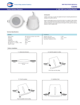
3.2 Packing list
Item Quantity Part
A 2 Speaker system
B 4 Tile rails
C 2 C-ring support
D 2 Grille
E 1 Owner’s manual
F 4 Support ring screws
G 2 Terminal connector
H 1 Service center card
I 1 Cutout template
J 2 Paint shield
C (x2)
B (x4)
I
J (x2)
A (x2)
D (x2)
G (x2)F (x4)
E
H
Figure3.1: EVID packing list

8 en | System overview EVID Ceiling Speaker Systems
2018.09 | 11 | F.01U.177.705 Installation manual Electro-Voice
3.3 Product Feature Identification
EVID C4.2, EVID-C6.2, EVID C8.2, EVID C8.2LP, EVID C8.2HC, and EVID C10.1 models
1
2
3
4
10
Grille
8
7
6
5
9
Figure3.2: Bottom of the speaker (left); Top of the speaker (center); Grille (right)
Item Description Item Description
1 Steel back can 6 Removable input terminal connector
2 Mounting screws 7 Seismic tab (auxiliary support ring)
3 Tap selector 8 Strain relief fitting
4 Grille safety tether hole 9 Terminal cover plate
5 Rotating mounting tabs 10 Grille safety tether
C4.2LP model
1
2 3
4
10
5
8
11
6
Grille
12
7
9
Figure3.3: Bottom of the speaker (left two illustrations); Top of the speaker (center); Grille (right)
Item Description Item Description
1 Mounting screws 7 Terminal cover plate
2 Grille safety tether hole 8 Removable input terminal connector
3 Tap selector 9 Terminal cover latch
4 Rotating mounting tabs 10 Steel back can
5 Terminal cover locking screw 11 Seismic tab (auxiliary support ring)
6 Strain relief fitting 12 Grille safety tether

EVID Ceiling Speaker Systems System overview | en 9
Electro-Voice Installation manual 2018.09 | 11 | F.01U.177.705
EVID Ceiling Series Systems (sold in pairs)
Model Part No Description
EVID C4.2 4" coaxial speaker with horn-loaded, Ti-coated tweeter
EVID-C4.2LP 4" coaxial speaker with horn-loaded, Ti-coated tweeter
EVID-C6.2 6.5" coaxial speaker, Ti-coated tweeter
EVID C8.2 8" coaxial speaker with horn-loaded, Ti-coated tweeter
EVID C8.2LP Same as C8.2 above except with low-profile back can
EVID C8.2HC 8" waveguide-coupled coaxial speaker with horn-loaded, Ti-coated tweeter
EVID C10.1 10" High performance subwoofer
EVID Series Ceiling Mount Speaker Accessories
Model Part No. Description
RR-42-B Rough-in plate for new construction involving the EVID C4.2 (package of 4)
RR-82 Rough-in plate for new construction involving the EVID-C4.2LP, EVID-C6.2, C8.2,
and C8.2LP (package of 4)
RR-810 Rough-in plate for new construction involving the EVID C8.2HC and C10.1 (package
of 4)
RPK-42 Rough-in package for new construction involving the C4.2 speaker only (package of
2)
RPK-82 Rough-in package for new construction involving the EVID-C4.2LP, EVID-C6.2, C8.2,
and C8.2LP speaker only (package of 2)
RPK-810-B Rough-in package for new construction involving the C8.2HC and C10.1 speaker
only (package of 2)
NOTE: All products are not available in all regions.

10 en | Installation and Wiring EVID Ceiling Speaker Systems
2018.09 | 11 | F.01U.177.705 Installation manual Electro-Voice
4 Installation and Wiring
The EVID mounting system has been designed so that, if necessary, the installation can be
done from beneath the ceiling. In some cases with a suspended ceiling grid, however, it may
be easier to access from both the top and bottom of the ceiling tile during the installation
process. Typical installation hardware needed for either suspended ceilings or sheetrock
ceilings is included. The ceiling speaker assembly is held in place by mounting tabs that
securely grip the ceiling material. Input wiring is attached to a removable terminal block
connector that can be prewired if necessary before speaker installation to speed up the
installation process.
INSTALLATION NOTE: USE OF OPTIONAL ROUGH-IN ACCESSORIES
For most installations, no additional hardware is needed. However, a two-step installation
procedure that is sometimes used for installation into sheetrock ceilings can be made easier
by the use of the optional RR and RPK series of rough-in accessories before the ceiling
material is installed. The rough-in accessories provide a cutout guide when many holes are to
be made in a production-line style installation and to ensure the speakers are positioned
correctly as the holes are cut in the sheetrock. Depending on the requirements, two types of
rough-in accessories are available.
RR Series Mounting Plates
RR series plates are made of flat sheet metal with holes to attach to the joists or trusses of a
building structure. The holes are drilled for nails or screws at 16 inches (406 mm), 20 inches
(508 mm) and 24 inches (610 mm) on-center. The installer can drill other holes as needed up
to a maximum of 24-3/4 inches (630 mm) apart. The sheetrock installs over the plate and the
plate provides a template for a blind cutout of the hole in the sheet rock. The ceiling material
is generally cut with a router-type cutting tool, using the plate ring as a cutout guide.
Figure4.1: Speaker mounting plate
RPK Series Kits
The RPK series rough-in kit contains a RR series plate with a standard 2 gang electrical box
mounted on the top with an attached short length of flexible conduit which connects to the
ceiling speaker conduit clamp on the speaker’s rear terminal cover. This accessory allows for
rigid conduit to be run to the box on the rough-in plate before the speaker or any sheetrock is
installed. After the sheetrock is installed the speaker can be wired up and mounted all from
below the ceiling.

EVID Ceiling Speaker Systems Installation and Wiring | en 11
Electro-Voice Installation manual 2018.09 | 11 | F.01U.177.705
Figure4.2: RPK mounting system
INSTALLATION NOTE: CONTROLLING VIBRATION
Because of their high performance, EVID ceiling loudspeakers can generate substantial
vibration, which can cause buzzing in loose sections of the ceiling structure. Depending on the
character of the ceiling tile and related components, dampening material may need to be used
under the tile rails or the edges of the tiles to eliminate rattles.
4.1 Step 1 — Cut the Hole
For suspended tile or sheetrock ceilings, cut out the hole either by tracing the cardboard
template or with a circular cutter set to the appropriate cutout size. If the wire has been pre-
installed, pull the wiring through the cutout hole.
Figure4.3: Cut ceiling hole
4.2 Step 2 — Install C-Ring and/or Tile Rails
All EVID speakers come packaged with two types of backing hardware: a C-ring and two tile
rails. For suspended ceiling installations, insert the C-ring through the hole cut in the ceiling
tile. Place the C-ring around the hole with the tabs located as shown in the illustration. Insert
the tile rails through the cut hole in the ceiling tile. Snap the two rails into the two tabs in the
C-ring and align the rails so that the ends extend OVER the T-channel grid on the side of the
tile. Secure the rails onto the C-ring tabs by inserting a screw though each tab into the rail.
Figure4.4: Secure rails to C-Ring

12 en | Installation and Wiring EVID Ceiling Speaker Systems
2018.09 | 11 | F.01U.177.705 Installation manual Electro-Voice
INSTALLATION NOTE: TILE RAILS AND C-RING
Each speaker comes with two tile rails which are designed to fit either standard 24-inch-wide
or 600-mm-wide tiles. It is important to note that the tile rail pieces do not actually attach to
the T-grid struts. The ends of the rails sit OVER the T-grid strut. Normally, the tile supports the
rails. The tile rails are pre-punched at regular intervals with holes along their length. This
allows the C-ring to be positioned at any point along the rail. If the tile comes out or falls
apart, the ends of the support rails fall onto the T-grid, which prevents the speaker assembly
from falling.
Always use all included support hardware when installing into suspended ceiling tiles to make
sure the installation is secure.
For sheetrock ceiling installations, the C-ring should be used by itself to reinforce the ceiling
material and to spread out the pressure from the speaker hold-down tabs. Guide the C-ring
through the cut hole in the ceiling, and place it on the back side of the hole before inserting
the speaker.
4.3 Step 3 — Attach Wiring to the Terminal Connector
Insert the bare end of wire into the appropriate connector terminals and screw down the hold-
down screw until tight, using a small screwdriver.
INSTALLATION NOTE: CONNECTOR
Figure4.5: Tighten with screwdriver
WIRING GUIDELINES
The input connector’s four terminals are numbered and marked on the connector. Pins 1 and
2 are positive (+); pins 3 and 4 are negative (-).
Note: Pin 1 is connected to Pin 2 and Pin 3 is connected to Pin 4 inside the speaker. Pins 1
and 4 are used as daisy-chain connections to other loudspeakers.
There are two possible layouts for wiring a group of speakers; wiring in parallel or Daisy-
Chaining.
Wiring in parallel
Connect the wire pair of the subsequent speaker to pins 2 and 3. When one input connector is
removed, subsequent speakers will remain connected.

EVID Ceiling Speaker Systems Installation and Wiring | en 13
Electro-Voice Installation manual 2018.09 | 11 | F.01U.177.705
From amplifier or
previous speaker
To next speaker
Figure4.6: Parallel wiring
Daisy-Chaining
Connect the wire pair of the subsequent speaker to pins 1 and 4. When one input connector is
removed, subsequent speakers will also be disconnected.
From amplifier or
previous speaker
To next speaker
Figure4.7: Daisy-Chain wiring
INSTALLATION NOTE: SUBWOOFER POLARITY
When adding a subwoofer, be sure to observe the correct polarity. The C10.1 subwoofer has
been designed for optimum performance when used with the C4.2 or C4.2LP. In order to
maximize the low frequency output when used with the C6.2 , C8.2, C8.2LP or C8.2HC, the
polarity of the C10.1 subwoofer should be reversed.
C10.1 Subwoofer C4.2 Loudspeaker
+
-
C4.2LP Loudspeaker
Figure4.8: Subwoofer polarity with C4.2/C4.2LP
C10.1 Subwoofer
C8.2/C8.2HC/C8.2LP
Loudspeaker
+
-
+
-
C6.2 Loudspeaker
Figure4.9: Subwoofer polarity with C6.2 or C8.2/C8.2HC/C8.2LP

14 en | Installation and Wiring EVID Ceiling Speaker Systems
2018.09 | 11 | F.01U.177.705 Installation manual Electro-Voice
Plugging in the connector
When all wiring has been completed to the connector, plug the input connector (A) into the
socket in the speaker’s terminal cup (B). Tighten all screws to eliminate vibration.
Hold-down
screw (E)
Input connector (A)
Terminal
block (B)
Strain
relief
screws (D)
Horizontal
screw (C)
Plug connector into socket (except C4.2LP)
Input connector (A)
Terminal block (B)
Figure4.10: Plug connector into socket for the C4.2LP
Reinstalling the terminal cover plate for the EVID-C4.2LP
To reinstall the terminal cover plate, do the following:
1. Thread the wire through the strain relief fitting on the terminal cover plate.
2. Guide the terminal cover plate (A) into the terminal cover latch (B).
A
C
B
3. Insert the terminal cover locking screw (C) into the terminal cover plate.
4. Tighten the terminal cover locking screw.
Ensure the terminal cover plate is secure. Do not over tighten the terminal cover locking
screw.
4.4 Step 4 — Secure the Cable to the Speaker
Fully loosen the horizontal screw (C) shown in Plugging in the connector, page 14, then the
strain relief screws (D). Run the wires through the opening in the fitting and plug the input
connector (A) into the speaker’s terminal block (B). Then tighten the strain relief fitting as
follows:

EVID Ceiling Speaker Systems Installation and Wiring | en 15
Electro-Voice Installation manual 2018.09 | 11 | F.01U.177.705
Plenum cable
If plenum cable is used, slide the wiring through the strain relief fitting on the terminal cover
plate. Hold the strain relief fittings tight around the cable. Tighten the strain relief screws first,
then the horizontal screw. In the cases of insulated speaker wire and plenum cable, it is often
possible to provide acceptable strain relief force by simply tightening the strain relief screws
onto the terminal cover plate.
Figure4.11: Secure cable through fitting except C4.2LP (left); Secure cable through fitting for the C4.2LP
(right)
Alternate conduit fitting
If the installation used flexible (BX) or rigid (EMT) conduit, an alternate conduit fitting can be
used.
INSTALLATION NOTE: ALTERNATE CONDUIT FITTINGS
Some cases require alternate fittings, many of which are available through most electrical
suppliers. Simply remove the existing fitting by unscrewing the two hold-down screws,
exposing a 7/8-inch (22 mm) knockout hole. Then install the alternate fitting. Make sure to
always use a listed fitting in accordance with your area’s building codes and regulations.
Figure4.12: Alternate conduit fitting except C4.2LP (left); Alternate conduit fitting for the C4.2LP (right)
4.5 Step 5 — Mount the Speaker into the Ceiling
Push the speaker into the ceiling hole until the front baffle rim is flush with the ceiling. Tighten
the mounting tabs by turning the screw clockwise until the speaker is secure. Please note that
the first clockwise quarter-turn rotates the attachment tabs outward. The remaining turns
tighten the tabs down onto the back of the ceiling surface.

16 en | Installation and Wiring EVID Ceiling Speaker Systems
2018.09 | 11 | F.01U.177.705 Installation manual Electro-Voice
Figure4.13: Mount speaker into ceiling
!
<=12 in. lbs.
(1.35 Nm)
Figure4.14: Tighten mounting tabs
INSTALLATION NOTE: MOUNTING TABS
For each attachment screw, first turn one half-turn counterclockwise to release the mounting
tab from its guide.
4.6 Step 6 — Connect an Auxiliary Support Line
Note the support ring on the back of the speaker. The ring allows for connection to a
independent and secure anchor point. Construction codes often require the use of this
secondary support point.
!
Caution!
Ceiling mount speaker’s safety cable
The safety cable should be installed with 1-3 inches (25.4-76.2 mm) of slack.

EVID Ceiling Speaker Systems Installation and Wiring | en 17
Electro-Voice Installation manual 2018.09 | 11 | F.01U.177.705
Figure4.15: Attach auxillary support line except the C4.2LP (left); Attach auxillary support line for the
C4.2LP (right)
4.7 Step 7 — Adjust Tap Selector
The tap selector switch is located on the front baffle. Adjust the speaker to the appropriate
tap setting before installing the grille. In some 70V/100V constant voltage installations it is
advisable to leave the grilles off if final speaker audio level balance adjustments are to be
made later. After the levels are adjusted the grilles can then be installed.
Figure4.16: Adjust tap selector (left: C4.2/C4.2LP/C6.2/C8.2/C8.2LP; right: C10.1/C8.2HC )
EVID C4.2, C4.2LP, C6.2, C8.2, and C8.2LP
In addition to the 8-ohm setting, the power taps are 30 W, 15 W, 7.5 W, and 3.7 W at both
70.7V and 100V, with a 1.8 W tap for 70.7V only.
EVID C8.2HC and C10.1
In addition to the 8-ohm setting, the power taps are 60 W, 30 W, and 15 W at both 70.7V and
100V, with a 7.5 W tap for 70.7V only.
4.8 Step 8 — Attach the Grille
INSTALLATION NOTE: GRILLE SAFETY FEATURE
EVID grilles features a unique safety tether to prevent the grille from falling if the grille is
removed or comes loose after installation.
First, install the grille’s safety tether by pushing the grille fastener into the hole in the front of
the baffle. Second, press the grille into place until the front of the grille is flush with the rim of
the baffle. Make sure the grille is securely seated to prevent it from vibrating loose.

18 en | Installation and Wiring EVID Ceiling Speaker Systems
2018.09 | 11 | F.01U.177.705 Installation manual Electro-Voice
If you need to remove the grille, the easiest way is to insert two bent paper clips or other
pointed objects into holes in the grille, then apply slow even pressure to pull down on the
grille until that section of the grille comes out slightly. Continue the same procedure around
the perimeter of the grille, loosening a portion at a time until the grille is removed.
1
2
Figure4.17: Attach the grille

EVID Ceiling Speaker Systems Troubleshooting | en 19
Electro-Voice Installation manual 2018.09 | 11 | F.01U.177.705
5 Troubleshooting
Problem Possible Causes Action
No output Amplifier Ensure the amplifier channel is being fed an input signal (preferably
via a signal input indicator on the amplifier).
Verify the amplifier channel’s volume is turned up.
Connect the loudspeaker and cable, which had no output to another
amplifier channel, ensuring an input signal is fed to the new amplifier
channel. If you then get output, the problem was the amplifier
channel. If not, then the problem is either the cable or the
loudspeaker.
Loudspeaker
cables(s)
Replace the cable(s) connecting the loudspeaker system and
amplifier.
Questionable or
intermittent output,
such as crackling
Faulty connection Ensure all cabling for proper connector contact. A bad connection can
result in intermittent contact or dramatically increased resistance,
which in turn can cause reduces output or noises unrelated to the
signal.
Improper power
tap setting
Verify the power tap setting under the loudspeaker grille is
appropriate for the installation and amplifier chosen.
Constant noise
such as buzzing,
hissing, or
humming
A faulty electronic
device in the signal
chain
Loudspeakers cannot generate these sounds by themselves; you may
have a faulty electronic device in the signal chain.
Poor system
grounding
Check and correct the system grounding, as required.
Poor low-frequency
output
Out-of-polarity
hookup between
multiple
loudspeakers
When two loudspeakers are hooked up out of polarity (out of phase),
the low frequencies cancel each other out. Try reversing the polarity
of one of the loudspeakers either by turning around a dual-banana
plug at the amplifier or by reversing the tip/sleeve leads on the jack.
Which ever condition results in greater low-frequency output is the in-
polarity condition.
If these suggestions do not solve your problem, contact your nearest Electro-Voice dealer or
Electro-Voice distributor.

20 en | Technical data EVID Ceiling Speaker Systems
2018.09 | 11 | F.01U.177.705 Installation manual Electro-Voice
6 Technical data
EVID C4.2 and EVID-C4.2LP
Specification EVID C4.2 C4.2LP
Frequency response 65 Hz - 20 kHz 60 Hz - 20 kHz
Sensitivity (SPL 1 W/1 m) 86 dB
Coverage pattern 130° conical
Power handling (@ 8Ω) 50 W (with overload protection)
Rated Impedance 8 Ω
Recommended High-Pass
frequency:
65 Hz
Input configuration 8Ω; 70V/100V
70V/100V power taps 1.8 (70V only)/3.7/7.5/15/30 W
LF transducer 4 in (100 mm) high-compliance
driver (weatherized cone)
4 in (100 mm) high-compliance
driver (weatherized cone)
HF transducer 0.75 in (19 mm) Ti-coated dome 0.75 in (19 mm) Ti-coated dome
Mounting system Integrated 3-point toggle anchors Integrated 4-point toggle anchors
Acoustic design Ported cabinet, two-way design, internally damped, w/passive
crossover
Cabinet construction Steel enclosure and UL94V-0 rated baffle and bezel
Grille construction Powder-coated steel
Color White (paintable)
Cutout dimensions (diam.) 7.1 in (180 mm) 10.6 in (269 mm)
Dimensions (depth x diam.) 6.9 in x 8.3 in (176 mm x 211 mm) 3.7 in x 11.8 in (94 mm x 300 mm)
Net weight 6 lb (2.7 kg) 7.35 lb (3.32 kg)
Included accessories Tile bridge, mounting ring
Safety agency ratings UL 1480
Safe for use in air handling spaces per UL 2043
EVID-C6.2 and EVID C8.2
Specification EVID-C6.2 EVID C8.2
Frequency response 50 Hz - 20 kHz 50 Hz - 20 kHz
Sensitivity (SPL 1 W/1 m) 90 dB 91 dB
Coverage pattern 120° conical 110° conical
Power handling (@ 8Ω) 75 W (with overload protection)
Rated Impedance 8 Ω
/