
BW
AUTO
6.0
MODE
AM SYNC
A-B
TIME
MEM
VFO A = B
A = B
PRE ATTN
ANT 1 2 VHF
AGC S F
NOTCH
NB N W
NAME
TIMER
STEP
CLK/FREQ
LOCK
TUNE
SCAN
NOTCH TONE
SCAN
MEM
6.0
4.0
AM/
SYNC
FM
2.3
1.8 LSB USB
0.5
AUTO CW RTTY
BANDWIDTH
MODE
LIST
2
A - B
3
SEEK
4
TIME
5
CARR
6
CLK
7
LAMP
8
BEEP
9
F
DEL
0
V M
M V
SQUELCH
PASSBAND
OFFSET
VOL RF
MIN
0
-
+
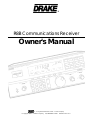
R8B Communications Receiver
1 3 5 7 9 20 40 60
S UNITS DECIBLES
SIGNAL
M/KHz
MEM
1
CLR
kHz
®
© Copyright 1997 R. L. Drake Company P/N: 3851305A-9-1997 Printed in the U. S. A.
is a registered trademark of the R. L. Drake Company
®
Owner's Manual
R8B Communications Receiver

Date: October 16, 1995 Signature ___________________
Ref. No. 953427 Name: G. Raithel Dipl.-Ing.
Signature ____________________
Date: July 01, 1997 Name: Ronald E. Wysong____
(Stamp)
®
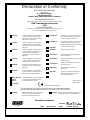
Declaration of Conformity
We, Manufacturer/Importer
(Full address)
R. L. Drake Company
230 Industrial Drive
Franklin, Ohio 45005 United States of America
declare that the product
(Description of the apparatus, system, installation to which it refers)
R8B Communications Receiver
1294
is in conformity with
(reference to the specifications under which conformity is declared)
in accordance with 89/336 EEC-EMC Directive
EN 55011
EN 55013
EN 55014
EN 55015
EN 55020
EN 55022
DIN V VDE 0855
part 10
part 12
CE marking
EN 60065
Cabled distribution systems; Equipment
for receiving and/or distribution from
sound and television signals
Limits and methods of measurement
of radio disturbance characteristics of
industrial, scientific and medical (ISM)
high frequency equipment
Limits and methods of measurement
of radio disturbance characteristics of
broadcast receivers and associated
equipment
Limits and methods of measurement
of radio disturbance characteristics of
household electrical appliances,
portable tools and similar electrical
apparatus
Limits and methods of measurement
of radio disturbance characteristics of
flourescent lamps and luminaries
immunity from radio interference of
broadcast receivers and associated
equipment
Limits and methods of measurement
of radio disturbance characteristics of
information technology equipment
Disturbances in supply systems caused
by household appliances and similar
electrical equipment "Harmonics"
Disturbances in supply systems caused
by household appliances and similar
electrical equipment "Voltage fluctuations"
Generic emission standard
Generic immunity standard
EN 61000-3-2*
EN 61000-3-3*
EN 50081-1
EN 50082-1
prEN 55024-2
prEN 55024-3
pr EN 55024-4
prENV 50142
ENV 50141
Electrostatic discharge requirements
"ESD" (IEC 801-2)
Radiated, radio frequency electromagnetic
field (IEC 801-3)
Electrical fast transient requirements
"Burst" (IEC 801-4)
Surge immunity requirements
(IEC 801-5)
Immunity to conducted disturbances
induced by radio frequency fields
above 9kHz (IEC 801-6)
* Replacement of
EN60555-2/-3
Safety requirements for mains operated
electronic and related apparatus for
household and similar general use
The manufacturer also declares the conformity of above mentioned product
with the actual required safety standards in accordance with LVD 73/23 EEC.
(EC conformity marking)
Manufacturer/Importer
EN 60950
Safety for information technology equipment
including electrical business equipment
EMC Tested by electronic GmbH

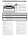
TO REDUCE THE RISK OF FIRE OR ELECTRIC SHOCK, DO NOT EXPOSE THIS APPLIANCE
TO RAIN OR MOISTURE.
DO NOT OPEN THE CABINET, REFER SERVICING TO QUALIFIED PERSONNEL ONLY.
TO PREVENT ELECTRIC SHOCK, DO NOT USE THE THREE WIRE CORD WITH AN EXTENSION
CORD RECEPTACLE OR OTHER OUTLET UNLESS THE BLADES CAN BE FULLY INSERTED TO
PREVENT BLADE EXPOSURE.
POUR PREVENIR LES CHOCS ELECTRIQUES, NE PAS UTILISER CETTE FICHE POLARISEE
AVEC UN PROLONGATEUR, UNE PRISE DE COURANT OU UNE AUTRE SORTIE DE COUR-
ANT, SAUF SI LES LAMES PEUVENT ETRE INSEREES A FOND SANS EN LAISSER AUCUNE
PARTIE A DECOUVERT.
WARNING:
CAUTION:
ATTENTION:
An appliance and cart combination should be moved
with care. Quick stops, excessive force and uneven
surfaces may cause the appliance and cart combina-
tion to overturn.
The lightning flash with arrow head symbol, within an
equilateral triangle, is intended to alert the user to the
presence of uninsulated "dangerous voltage" within
the product's enclosure that may be of sufficient
magnitude to constitute a risk of electric shock to
persons.
The exclamation point within an equilateral triangle is
intended to alert the user to the presence of impor-
tant operating and maintenance (servicing) instruc-
tions in the literature accompanying the appliance.
¡WARNING!
WARNING: TO PREVENT FIRE OR
ELECTRICAL SHOCK DO NOT
EXPOSE TO RAIN OR MOISTURE
RISK OF ELECTRIC SHOCK
DO NOT OPEN
WARNING: TO REDUCE THE RISK OF ELECTRIC
SHOCK,
DO NOT REMOVE COVER (OR BACK)
NO USER-SERVICABLE PARTS INSIDE
REFER SERVICING TO QUALIFIED PERSONNEL
1. Read Instructions—All the safety and operating instructions should be
read before the appliance is operated.
2. Retain Instructions—The safety and operating instructions should be
retained for future reference.
3. Heed Warnings—All warnings on the appliance should be adhered to.
4. Follow Instructions—All operating and use instructions should be
followed.
5. Cleaning—Unplug this appliance from the wall outlet before cleaning.
Do not use liquid cleaners or aerosol cleansers. Use a damp cloth for
cleaning.
6. Do Not Use Attachments—not recommended by the manufacturer or
they may cause hazards.
7. Water and Moisture—Do not use this product near water—for example,
near a bathtub, wash bowl, kitchen sink, laundry tub, in a wet basement,
or near a swimming pool—and the like.
8. Accessories—Do not place this product on an unstable cart, stand,
tripod, bracket, or table. The product may fall, causing serious injury to a
child or adult, and serious damage to the appliance.
9. Ventilation—This product should never be placed near or over a
radiator or heat register. This product should not be placed in a built-in
installation such as a bookcase or rack unless proper ventilation is provided
or the manufacturer’s instructions have been adhered to. Any slots or
openings in the cabinet are provided for ventilation. To ensure reliable
operation of the video product and to protect it from overheating, these
openings must not be blocked or covered. The openings should never be
blocked by placing the product on a bed, sofa, rug, or other similar surface.
10. Grounding or Polarization—This product is equipped with a 3- wire
line cord receptacle. It is intended for use with a 3-wire properly grounded
power socket. Do not defeat the safety purpose of the supplied line cord
and plug.
10A. Mise à la terre ou Polarisation—Cet appareil est équipé avec un
cordon d'alimentation à trois fils. Il est a brancher sur une prise ayant un
connecteur a la terre. Assurez-vous que la connection a la terre ne manque
pas.
11. Power Sources—This product should be operated only from the type
of power source indicated on the marking label. If you are not sure of the
type of power supplied to your home, consult your appliance dealer or local
power company.
12. Power-cord Protection—Power-supply cords should be routed so
they are not likely to be walked on or pinched by items placed upon or
against them. Pay particular attention to cords at plugs, convenience
receptacles, and the point where they exit from the appliance.
13. Lightning—For added protection for this product during a lightning
storm, or when it is left unattended and unused for long periods of time,
unplug it from the wall outlet.
14. Power Lines—An outside antenna system should not be located in the
vicinity of overhead power lines, other electric light or power circuits, where
it can fall into such power lines or circuits. When installing an outside
antenna system, extreme care should be taken to keep from touching such
power lines or circuits as contact with them may be fatal.
Important Safeguards i

ii Important Safeguards, continued
" INSTALL WIRING ACCORDING TO THE CANADIAN ELECTRICAL CODE"
"EFFECTUER LE CABLAGE CONFORMEMENT AU CODE CANADIEN DE L' ELECTRICITE"
15. Overloading—Do not overload wall outlets and extension cords as this
can result in a risk of fire or electric shock.
16. Object and Liquid Entry—Never push objects of any kind into this
product through openings as they may touch dangerous voltage points or
short-out parts that could result in a fire or electric shock. Never spill liquid
of any kind on the product.
17. Servicing—Do not attempt to service this product yourself as opening
or removing covers may expose you to dangerous voltage or other
hazards. Refer all servicing to qualified service personnel.
18. Damage Requiring Service—Unplug this product from the wall outlet
and refer servicing to qualified service personnel under the following
conditions:
a. When the power-supply cord or plug is damaged.
b. If liquid has been spilled, or objects have fallen into the product.
c. If the product has been exposed to rain or water.
d. If the product does not operate normally by following the operating
instructions. Adjust only those controls that are covered by the operating
instructions. An improper adjustment may result in damage and will often
require extensive work by a qualified technician to restore the product to its
normal operation.
e. If the product has been dropped or the cabinet has been damaged.
f. When the product exhibits a distinct change in performance—this
indicates a need for service.
19. Replacement Parts—When replacement parts are required, be sure
the service technician has used replacement parts specified by the
manufacturer or have the same characteristics as the original parts.
Unauthorized substitutes may result in fire, electric shock or other hazards.
20. Safety Check—Upon completion of any service or repairs to this
product, ask the service technician to perform safety checks to determine
that the product is in proper operating condition.
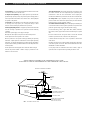
21. Outdoor Antenna Grounding—Before attempting to install this prod-
uct, be sure the antenna or cable system is grounded so as to provide some
protection against voltage surges and built-up static charges.
a. Use No.10 AWG (5.3mm
2
) copper, No.8 AWG (8.4mm
2
) aluminum,
No.17 AWG (1.0mm
2
) copper-clad steel or bronze wire or larger, as ground
wire.
b. Secure antenna lead-in and ground wires to house with stand-off
insulators spaced from 4 feet (1.22m) to 6 feet (1.83m) apart.
c. Mount antenna discharge unit as close as possible to where lead-in
enters house.
d. A driven rod may be used as the grounding electrode where other types
of electrode systems do not exist. Refer to the National Electrical Code,
ANSI/NFPA 70-1990for information.
e. Use jumper wire not smaller than No.6 AWG 13.3mm
2
) copper or
equivalent, when a separate antenna grounding electrode is used.
POWER SERVICE GROUNDING
ELECTRODE SYSTEM
(NEC ART 250, PART H)
GROUND CLAMPS
GROUNDING CONDUCTORS
(NEC SECTION 810-21)
ANTENNA
DISCHARGE UNIT
(NEC SECTION 810-20)
ANTENNA
LEAD IN
WIRE
ELECTRIC
SERVICE
EQUIPMENT
GROUND CLAMP
NEC - NATIONAL ELECTRIC CODE
EXAMPLE OF ANTENNA GROUNDING

Table of Contents iii
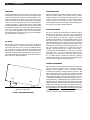
Thank you for purchasing a Drake R8B Communications
Receiver. This receiver has been designed and manu-
factured to high quality standards, and will provide
reliable operation for many years.
Please carefully read the Owner's Manual in order to
take advantage of the many interesting features that
will provide enjoyable listening to radio broadcasts
around the world.
17
18
18
18
18
18
19
19
20
20
21
21
22
22
22
22
22
23
25
26
26
26
26
26
26
26
27
31
32
33
35
35
36
37
i
iii
1
1
2
3
4
5
6
8
10
11
12
12
12
12
12
12
13
13
14
14
14
14
15
15
15
15
15
16
16
Memory Functions
Memory Channel Programming
Recalling A Memory Channel
Deleting A Memory Channel
Erase All Memory Channels
Locking A Memory Channel
Scan Functions
Scan Memory
Scan Memory List Block
Locking A Memory Channel
Scan A - B
Important Notes About Scanning
Clock and Timer Functions
Time Display
Setting The 24 Hour Clocks
Timer Operation
Setting Timer On/Off Times
Enabling/Disabling Timer Operation
Timer Connector Interface
Special Use Features and Functions
Function Line Invert
Setting Power Off (On) Lamp Brightness
10 kHz/9 kHz Scan
Delete All Memory Locations
Power On Button Functions
Held Button Functions
RS232C Interface
Glossary of Terms
Suggested References
Quick Reference Guide
Troubleshooting
Special Display Messages
Service
Warranty
Warning: The R8B Communications Receiver complies with FCC
rule Part 15. Any changes or modifications to the receiver, without
expressed approval of the R. L. Drake Company, could cause the
receiver to violate the FCC Compliance rules.
Important Safeguards
Table of Contents
Introduction
General Description
Specifications / Accessories
Safety Voltage Selection
Installation
Unpacking
Location
Fixed Installation
Mobile Installation
Antenna Requirements
Installation Diagram
Front Panel Description
Front Panel Display
Rear Panel Description
Mute Operation of the Receiver
Getting Started
General Operating Information
Microprocessor Reset
Beep Tones
Getting Started
Frequency Step Selection
Dual VFO's
Direct Frequency Entry
Front Panel Lock
Passband Offset Operation
Notch Operation
AM Synchronous Detector
RF Function (Attenuator/Preamplifier)
Noise Blanker
CW Operation
RTTY Operation
SSB Operation
FM Operation
Gain and AGC Operation

iv
This page left intentionally blank.

BW
AUTO
6.0 4.0
2.3 1.8
0.5
MODE
AM SYNC
LSB USB
CW FM
RTTY
SCAN
MEM
LIST
A-B
SEEK
TIME
CARR
MEM
TUNE
VFO A = B
A = B
PRE ATTN
ANT 1 2 VHF
AGC S F
NOTCH
NB N W
NAME
12 ON OFF
TIMER
STEP
CLK/FREQ
LOCK
F
TUNE
SCAN
NOTCH TONE
SCAN
MEM
6.0
4.0
AM/
SYNC
FM
2.3
1.8 LSB USB
0.5
AUTO CW RTTY
BANDWIDTH
MODE
LIST
2
A - B
3
SEEK
4
TIME
5
CARR
6
CLK
7
LAMP
8
BEEP
9
F
DEL
0
V M
M V
SQUELCH
PASSBAND
OFFSET
VOL RF
MIN
0
-
+
R8B Communications Receiver
1 3 5 7 9 20 40 60
S UNITS DECIBLES
SIGNAL
M/KHz
MEM
1
CLR
kHz
MHz
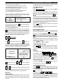
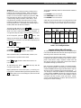
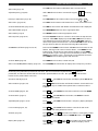
A PASSBAND OFFSET control also aids in reducing or
eliminating interfering signals by electronically shifting the
receiver's IF frequencies without disturbing the operating
frequency. This action allows the operator to electroni-
cally move interfering signals out of the receiver’s pass-
band thus utilizing the high degree of selectivity provided
by the High-Q, 8-pole IF filter.
Other built-in reception aids include selectable AGC
speed, dual antenna inputs, noise blanker(NB), RF pream-
plifier for enhancing weak signals, RF attenuator for further
improvement of strong signal handling capabilities, ad-
justable RF gain, NOTCH, TONE and SQUELCH controls.
Two independent, real time clocks provide a local and
alternative time selection. Also provided is a two event
timer.
A programmable memory area allows for 1000 independ-
ent receive memories. In addition, these memories are
stored in a battery backed-up memory chip to ensure
memory retention during power line failure. Any of these
memories may be altered by the operator and re-stored.
These memory channels may be accessed manually or
by various scanning methods.
Finally, a built-in RS-232 compatible interface allows com-
plete digital control of the receiver including memory and
scanning functions.
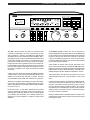
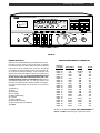
The R8B communications receiver is a microprocessor
controlled, synthesized, all mode, world band receiver
with continuous coverage capability from 100 through
30,000 kHz. The receiver offers excellent sensitivity, selec-
tivity, high dynamic range and offers features for the most
demanding shortwave reception. Conveniently located
front panel controls allow for rapid operator program-
ming and ease of use. Operating mode and correspond-
ing bandwidth are quickly selected by front panel but-
tons. The selectable AC input allows for operation around
the world. In addition, a DC input is provided for mobile
operation.
A High-Q, 8-pole, electronically switched IF filter provides
a range of five commonly used bandwidths. These band-
widths are automatically selected by mode, however
any bandwidth may be selected at the touch of a button.
The front panel liquid crystal display provides visual feed-
back to the operator of the current status of the receiver.
The seven digit frequency display allows tuning resolution
to 10 Hz accuracy.
In the AM mode, a selectable sideband synchronous
detector (SYNCHRO) allows for enhanced reception by
eliminating or reducing distortion due to fading signals
and allowing the passband to be shifted toward one
sideband, to reject interference, without causing audio
distortion.
Introduction - General Description 1

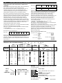
2 Introduction - Specifications / Accessories
Frequency Range
Modes
Sensitivity: SSB, CW (10dB
S+N/N)
Sensitivity: AM
(10dB S+N/N, 1000 Hz,
30% mod)
Sensitivity: FM
(12 dB SINAD)
Frequency Stability
Frequency Accuracy
Selectivity: AM, LSB, USB,
RTTY, CW
FM Only
Ultimate Selectivity
Image Rejection
IF Rejection
Dynamic Range
100-30,000 kHz
AM, LSB, USB, CW, RTTY, FM
0.5 µV nominal, 100-30,000 kHz
(preamp off)
Less than 0.25µV, 100-30,000 kHz
(preamp on)
1.5 µV nominal, 100-30,000 kHz
(preamp off)
Less than 1.0 µV, 100-30,000 kHz
(preamp on)
Less than 0.5 µV, 100-30,000 kHz
±5ppm, -10
0
to 50
0
C
Better than ±100 Hz, -10
0
to
50
0
C
6 KHz @ -6 dB, less than 12 kHz
@ -60 dB
4 KHz @ -6 dB, less than 8 kHz
@ - 60 dB
2.3 KHz @ -6 dB, less than
4.5 KHz @ -60 dB
1.8 KHz @ -6 dB, less than
3.6 KHz @ -60 dB
500 Hz @ -6 dB, less than
1.5 KHz @ -60 dB
12 KHz @ -6 dB, less than
25 KHz @ -60 dB
Greater than 95 dB
Greater than 80 dB,
100-30,000 kHz
Greater than 80 dB, 45 MHz
Greater than100 dB, 50 kHz
97 dB, 100-30,000 kHz @ 100 kHz
spacing
IP
3
- Intercept Point
(preamp off)
1st IF
2nd IF
AGC
Ant 1, Converter
Ant 2
Notch Filter Attenuation
External Speaker Output
Line Outputs
AC Power Requirements
DC Power Requirements
Operating Temperature
Weight
Size
+20 dBm @
100 kHz spacing
-20 dBm @
5 kHz spacing
45 MHz
50 kHz
Threshold: 0.8 µV
Attack time: 1mS
Release time: SLOW: 2 Sec
FAST: 300mSec
Nominal 6 dB change in au-
dio output for 100 dB input
change above AGC
threshold
50 Ohms unbalanced
50 or 500 Ohms unbal-
anced
AF type, 40 dB min. Depth
(500-5000 Hz)
2.5 W, 4 Ohms @ less than
5% distortion
300 mV, 4.7K Ohms
100/120/200/240VAC,
±10%
50 or 60 Hz, 40 Watts
nominal
11-16 VDC @ 2 A
-10
0
to +50
0
Celsius
13 lbs. (5.9 Kg)
Width 13 1/8" (33.4 cm)
Height 5 1/4" (13.4 cm) in-
cluding feet
Depth 13" (33 cm), includ-
ing front knobs and rear
connectors
ACCESSORIES
Accessories for the receiver include:
1) A VHF converter with frequency coverage of 35-55 MHz
and 108-174 MHz.
2) A complementary styled MS8 external speaker.
CAUTION: The optional VHF Converter accessory should
be installed by a qualified service technician to prevent
personal injury or damage to the equipment.

SAFETY/VOLTAGE SELECTION
WARNING!!!
Please read before applying power
The receiver is normally shipped with the input line voltage
selector switch set to 108-132 VAC for operation in the U.S.
and Canada. If your operating voltage is different than
this, please refer to FIGURE 1 below. The voltage select
switch is located on the rear panel and must be set to the
proper voltage range for your area. In addition, the
proper mains fuse may need to be installed. The unit may
be set to operate over the following voltage ranges: 90-
110 VAC, 108-132 VAC, 180-220 VAC and 216-264 VAC.
Most countries outside the U.S. and Canada use either
220 VAC or 240 VAC line voltage. Please be certain of the
operating voltage before connecting to the mains source.
The receiver will operate on either 50 Hz or 60 Hz line
frequency.
_________________________________________________________________
Note: The warranty does not cover damage as a result of
improper voltage selection, or replacement of fuse with
ratings other than those specified.
_________________________________________________________________
Introduction - Safety / Voltage Selection 3
Setting for 108-132 VAC
Fuse rating 400mA
Setting for 90-110 VAC
Fuse rating 400mA
Setting for 180-220 VAC
Fuse rating 200mA
Setting for 216-264 VAC
Fuse rating 200mA
FIGURE 1 VOLTAGE SELECTOR SWITCH SETTINGS
Antenna grounding is necessary if the unit is connected to
an outdoor antenna. Grounding of the antenna system
is required to protect against static build up and voltage
surges. Refer to section 810-21 of the National Electric
Code, ANSI/NFPA No. 70-1990.
The power cord and antenna lead-in should be discon-
nected if the unit is not to be used for an extended period
of time or if threatening weather containing damaging
lightning is likely.
CAUTION
In accordance with international safety
standards, this instrument is equipped with
a three-wire power cable receptacle. The
unit is shipped with a detachable type three-
wire power cable intended for nominal
115/127 VAC mains supply. When con-
nected to an appropriate power line out-
let, this cable grounds the instrument cabi-
net. For operation of this unit on nominal
220/240 VAC mains supply, use the proper
power cable assembly approved by your
local codes.
For use of this product outside the U. S. A. or
Canada on supply voltages of 220 VAC or
greater, the discharge resistor (4.7 Meg
Ohm) connected from the neutral wire ter-
minal of the AC input receptacle to the
receiver chassis must be removed.
Refer modification to a qualified service
technician.
108-
132V
90-
110V
216-
264V
180-
220V
DISCONNECT FROM
SUPPLY BEFORE
CHANGING RANGES
WARNING
108-
132V
90-
110V
216-
264V
180-
220V
DISCONNECT FROM
SUPPLY BEFORE
CHANGING RANGES
WARNING
108-
132V
90-
110V
216-
264V
180-
220V
DISCONNECT FROM
SUPPLY BEFORE
CHANGING RANGES
WARNING
108-
132V
90-
110V
216-
264V
180-
220V
DISCONNECT FROM
SUPPLY BEFORE
CHANGING RANGES
WARNING

UNPACKING
Carefully remove the receiver from the shipping carton
and examine it for evidence of damage. If any damage
is noted, immediately contact the transportation com-
pany responsible for delivery or return the unit to the
dealer from whom it was purchased. Keep the shipping
carton and all packing material for the transportation
company to inspect. The original carton and packing
material should be retained for repackaging should it be
necessary to return the unit. Inspect the packing material
for any accessories or printed material before storing the
box. Locate the registration card, fill out, and immedi-
ately return to the R. L. Drake Company to insure registra-
tion and validation of warranty.
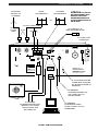
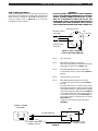
FIXED INSTALLATION
After unpacking the unit and checking the voltage select
switch for proper setting and correct fusing, connect
antenna system to the appropriate antenna input. Con-
nect AC cord to mains voltage. Connect ground system
to ground screw on rear panel of radio. Connect any
other external equipment at this time. Refer to Figure 3 for
the diagram of a typical fixed installation.
MOBILE INSTALLATION
For use in a mobile environment, the receiver includes a
fused external DC input connector. This connector is
located on the rear panel. The receiver works well with a
DC input voltage of 11-16 VDC. Typical automotive
systems supply 13.8 VDC. Due to the relatively low current
draw, the receiver may be powered from the vehicle’s
cigarette lighter socket. Connect DC power cord observ-
ing the correct polarity. An internal protection device will
protect the receiver from reverse polarity hookup. Con-
nect the mobile antenna(s) to appropriate antenna
input(s). This will typically be a whip antenna with a
coaxial cable thus permitting the cable to be run under
floor mats, etc. Connect a grounding wire from the
grounding screw on the rear panel to the vehicle's chas-
sis. To further reduce current draw from the vehicle’s
battery system, it is recommended the LCD backlighting
be turned off for extended listening periods.
LOCATION
The location of the receiver is not critical so long as
adequate clearance is provided to allow air circulation in
and around the unit. Do not cover any ventilation slots in
top cover or overheating may result. The ventilation slots
also double as a speaker grill and any blockage may
result in poor sound quality. For added operating conven-
ience, the front bail may be flipped down to elevate the
front of the unit. Refer to Figure 2
4 Installation
Side View of Receiver
FIGURE 2 ADJUSTING FRONT BAIL
ANTENNA REQUIREMENTS
The receiver incorporates internal switching to allow two
separate antenna systems to be connected simulta-
neously. Refer to Figure 3. Ant 1 is a 50 Ohm , SO-239
coaxial input requiring a mating PL-259 connector. This
input would typically be used as the primary antenna
input. Antennas such as dipoles, trapped dipoles, verti-
cals and beams will provide the best results. Ant 2 is a
compression terminal type connection, providing a choice
of high impedance (500 Ohms typical) or low impedance
(50 Ohms typical). Antennas such as long wires or end fed
Zepps will provide the best results. The best antenna will
depend on the frequency range and time of day for the
particular signal in question. Refer to publications such as
the ARRL Handbook or ARRL Antenna Manual (available
in most public libraries) for help on selection and/or con-
struction of the antennas mentioned above.

A N T 2
CONV
ANT 1
50
50
50 GND 500
EXT 11 - 16 VDC IN
- +
108-
132V
90-
110V
216-
264V
180-
220V
W A R N I N G
RISK OF ELECTRIC
SHOCK DO NOT OPEN
RISQUE DE CHOC
ELECTRIQUE NE PAS OUVRIR
AVIS
CAUTION: - RISK OF FIRE -
REPLACE FUSE AS MARKED AFTER
DISCONNECTING UNIT FROM AC LINE.
ATTENTION:- RISQUE D'INCENDIE -
REMPLACEZ FUSIBLE DU TYPE INDIQUÉ
APRÉS DEBRANCHER DU SECTEUR.
INT EXT
BOTH
EXT OUT OUT MUTE
SPEAKER
LINE AUDIO
INTERFACE
RS - 232C
DC
AC
DISCONNECT FROM
SUPPLY BEFORE
CHANGING RANGES
WARNING
40 WATTS 50/60 Hz
100VAC 400 mA
120VAC 400 mA
200VAC 200 mA
240VAC 200 mA
TYPE T
GND
TIMER
MADE IN U. S. A.
BY ®
4
2A
TYPE T
Installation, continued 5
FIGURE 3 INSTALLATION DIAGRAM
MS8 Speaker
EXTERNAL SPEAKER
(MS8)
TO PERIPHERAL
EQUIPMENT WITH LINE AUDIO
INPUTS SUCH AS CW/RTTY
DEMODULATORS, TAPE
RECORDERS , ETC.
TERMINAL
TO PERIPHERAL
EQUIPMENT PROVIDING
MUTING CONTROL SUCH AS
TRANSMITTERS
TO GOOD EARTH GROUND
(POWER SERVICE GROUND-
ING, ELECTRODE SYSTEM OR
WATER PIPE)
TO PERIPHERAL
EQUIPMENT WITH TIMED ON/
OFF CONTROL SUCH AS
TAPE RECORDERS
DC POWER PLUG TO
VEHICLE'S LIGHTER SOCKET
FOR USE WITH
OPTIONAL VHF
CONVERTER
DIPOLE
LOW IMPEDANCE
LONGWIRE
HIGH IMPEDANCE
OR
PL-259
AC POWER CORD
CONNECTION
50 OHM
COAXIAL
CABLE
50 OHM COAXIAL CABLE
- OR -
ATTENTION: LOCATE ANY
RECEIVER ANTENNAS SOME
DISTANCE AWAY FROM
TRANSMITTER ANTENNAS TO
AVOID POSSIBLE DAMAGE TO
THE RECEIVER

BW
AUTO
6.0 4.0
2.3 1.8
0.5
MODE
AM SYNC
LSB USB
CW FM
RTTY
SCAN
MEM
LIST
A-B
SEEK
TIME
CARR
MEM
TUNE
VFO A = B
A = B
PRE ATTN
ANT 1 2 VHF
AGC S F
NOTCH
NB N W
NAME
12 ON OFF
TIMER
STEP
CLK/FREQ
LOCK
F
TUNE
SCAN
NOTCH TONE
SCAN
MEM
6.0
4.0
AM/
SYNC
FM
2.3
1.8 LSB USB
0.5
AUTO CW RTTY
BANDWIDTH
MODE
LIST
2
A - B
3
SEEK
4
TIME
5
CARR
6
CLK
7
LAMP
8
BEEP
9
F
DEL
0
V M
M V
SQUELCH
PASSBAND
OFFSET
VOL RF
MIN
0
-
+
R8B Communications Receiver
1 3 5 7 9 20 40 60
S UNITS DECIBLES
SIGNAL
M/KHz
MEM
1
CLR
kHz
MHz
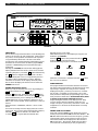
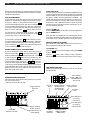
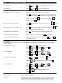
8) PASSBAND OFFSET - This control alters the position of the
receiver’s IF passband without disturbing the main tuning.
Normally, this control should be set at the “0” or 12 o’clock
position. This control is not active in FM mode.
9) SQUELCH - This control sets the signal level at which the
audio is muted. For normal operation, this control is set
fully counterclockwise.
10) TUNING (VFO) - The tuning wheel and the
and
buttons are the primary tuning controls of the re-
ceiver. Clockwise rotation of the tuning wheel increases
frequency and counterclockwise rotation decreases fre-
quency. The tuning wheel also incorporates variable
speed tuning. The faster the tuning wheel is rotated, the
faster the tuning speed.
TUNING WHEEL STEPS
The receiver can be programmed to tune in three
different resolutions (steps) with the corresponding
display readout. The three choices are as follows:
A) 1 kHz display readout (tuning in 1 kHz steps).
Used for fairly rapid frequency search.
B) 100 Hz display readout (tuning in 100 Hz steps).
Used for tuning AM and FM signals.
C) 10 Hz display readout (tuning in 10 Hz steps).
Used for tuning SSB, CW, or data signals.
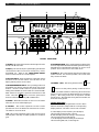
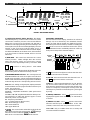
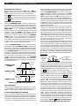
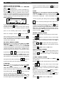
1) SIGNAL - This meter indicates the relative signal level in
S-units and dB above S9.
2) Display - The backlit, liquid crystal display provides the
current status of the receiver such as frequency, mode,
bandwidth, etc. Refer to the FRONT PANEL DISPLAY
section of this manual for a full description.
3) Function Buttons - These (6) buttons control the various
functions of the receiver which are indicated on the
display directly above each button.
4) MODE/BANDWIDTH Buttons - The operating mode and
bandwidth are directly entered with these front panel
buttons. Press the AUTO button to permit automatic
setting of bandwidth as mode is selected. Press the AM/
SYNC button to enable the synchronous detector in AM
mode. Press the
AM/
SYNC
button to turn the synchronous
detector off before selecting LSB or USB modes.
5) POWER - This button turns the receiver on or off. When
unit is off, the clock will be displayed.
6) VOLUME - This control adjusts the receiver’s audio
speaker level. Turn clockwise to increase level or counter-
clockwise to decrease level.
7) RF - This control adjusts the gain of the receiver and is
normally left in the fully clockwise position for maximum
gain.
FIGURE 4 FRONT PANEL
6 Front Panel Description
14 13 12 11 10 9 8 7 6 5
1 2 3 4

Front Panel Description, continued 7
Mode
LSB, USB, RTTY, CW
AM, FM
Tuning and
Display Resolution (Hz)
10
100
Table 1
The step size may be programmed per mode. The re-
ceiver, as shipped from the factory, has step sizes pro-
grammed as shown in Table 1 below:
To reset the receiver to the factory settings for STEP size,
AGC setting, BANDWIDTH, etc.:
Press the POWER button to turn the receiver off. Press the
CLR
button and hold while pressing the POWER button to
turn Power on. After three seconds, the receiver will reset.
BUTTON STEPS
The button increases and the button de-
creases the frequency by fixed steps with each depres-
sion as programmed. Pressing and holding either button
will allow continuous stepping up or down as long as the
button is depressed. The fixed steps are as follows:
To tune in 100 kHz steps, press the
F
button. With the
F
displayed, press the / buttons, as desired,
to tune in 100 kHz increments.
Note that, regardless of the / button step
increments, the display always indicates the programmed
tuning resolution (step) available by using the tuning
wheel at any frequency.
11) Program Buttons -
SCAN
(Scan) - Pressing this button starts a scan as defined
by the scan indicators (
SCAN
MEM
LIST
A-B
SEEK
TIME
CARR
) on the display.
Please refer to the SCAN FUNCTIONS section of this
manual for details.
MEM
(Memory) - Pressing this button in VFO mode switches
the receiver to memory mode. Please refer to the MEMORY
FUNCTIONS section of this manual for details.
V M
(VFO to Memory) - Pressing this button in VFO mode
transfers the current status of the receiver, for example,
frequency, mode, bandwidth, etc., into memory. Please
refer to the MEMORY FUNCTIONS section of this manual for
details.
M V
M/KHz
(MHz or kHz Frequency Readout or Memory to VFO)
- Pressing the
F
button followed by the
M V
M/KHz
button,
changes the frequency readout to MHz or kHz as desired.
Pressing this button in memory mode transfers the con-
tents of the current memory location, i.e., frequency,
mode, bandwidth, etc. to the selected VFO. Refer to the
MEMORY FUNCTIONS section of this manual for details.
F
(Function) - Pressing this button accesses secondary
functions, printed in orange, on the numeric buttons 0-9
and switches the function line on the display above the 6
function buttons.
DEL
0
to
BEEP
9
- These buttons are normally used for direct
numeric entries in VFO, memory, clock, and timer modes.
Each button also has a secondary function printed in
orange. These secondary functions are used as follows:
Press
F
,
MEM
1
to
CARR
6
for programming scan methods.
Refer to the SCAN FUNCTIONS section of this manual for
details.
Press
F
,
CLK
7
to access the clock. Refer to the CLOCK
& TIMER FUNCTIONS section of this manual for details.
Press
F
,
LAMP
8
to adjust display and signal meter back-
light intensity.
Press
F
,
BEEP
9
to turn audible beep on or off. Refer to
BEEP TONES page 12.
Press
F
,
DEL
0
to delete a program from a memory
location. See DELETING A MEMORY LOCATION page 18.
CLR
(Decimal) - This button is used when entering a
frequency directly with the numeric buttons. Also used in
conjunction with the
F
button to provide a Clear entry
function. See DIRECT FREQUENCY ENTRY page 13.
12) TONE - This control is used to modify the tonal quality
of the audio. Counterclockwise rotation increases bass
response. Flat response occurs at the 12 o'clock setting.
13) NOTCH - This control is used to “tune” the notch
frequency and is active when
AG S
NOTCH
is displayed. This
control is not active in FM mode.
14)
Headphone - This connector accepts a standard
1/4" diameter 2-circuit (monaural) or 3-circuit (stereo)
phone plug. Audio is monaural in either case. All speaker
outputs are automatically switched off when using head-
phones.
Frequency Range
100-540 kHz
540-1800 kHz
1800-30,000 kHz
Step
5 kHz
AM mode: 10 kHz
(9 kHz if programmed)
Other modes: 5 kHz
5 kHz

BW
AUTO
6.0 4.0
2.3 1.8
0.5
MODE
AM SYNC
LSB USB
CW FM
RTTY
SCAN
MEM
LIST
A-B
SEEK
TIME
CARR
MEM
TUNE
VFO A = B
A = B
PRE ATTN
ANT 1 2 VHF
AGC S F
NOTCH
NB N W
NAME
12 ON OFF
TIMER
STEP
CLK/FREQ
LOCK
F
kHz
MHz
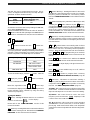
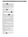
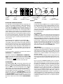
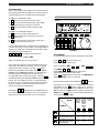
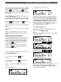
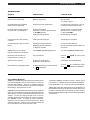
8 Front Panel Display
8
FIGURE 5 FRONT PANEL DISPLAY
3
15
4
6
7
911210 13 12 15 14
17
16
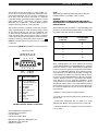
IMPORTANT - PLEASE READ
The function lines of the display, described in callouts 5)
through 17) are activated by the unmarked function
button located directly below the displayed function.
The primary function line is the top most line. Pressing the
F
allows access to the alternate function line (lower
line). Alternate function availability ‘times out’ after any
front panel activity which alters the display.
5)
F
- This annunciator lights to indicate that the alter-
nate function selection is enabled.
6) VFO A/B - This annunciator indicates the VFO in use. A
box
appears around the active VFO.
7) A=B - An ‘=’ sign appears between the ‘A’ and ‘B’ of the
top function line to indicate that one of the VFO’s has
been set to the same frequency as the other. This function
serves as a temporary ‘scratchpad’ memory of the first
VFO frequency as the second VFO frequency is changed
by tuning.
8) PREamp/ATTENuator - A box
appears around the
appropriate legend when the Preamp or attenuator is
activated.
9) ANTenna 1/2/VHF - A box
appears around the
selected antenna input: ‘ANT 1’, ‘ANT 2’ or the ‘VHF’
('CONV') connector at the rear panel of the receiver.
NOTE: VHF is only accessible when the accessory VHF
Converter module is installed.
Function
Lines
Function
Buttons
TUNE
SCAN
SCAN
MEM
LIST
2
A - B
3
SEEK
4
TIME
5
CARR
6
CLK
7
LAMP
8
BEEP
9
F
DEL
0
V M
M V
A B CARR
VFO A = B
A = B
PRE ATTN
ANT 1 2 VHF
AGC S F
NOTCH
NB N W
NAME
12
ON
OFF
TIMER
STEP
CLK/FREQ
LOCK
M/KHz
MEM
1
CLR
1) 7-Digit Apha/Numeric Display Readout - This display
indicates frequency, in ‘MHz’ or ‘kHz’ as selected, of the
current VFO or Memory channel. The readout will also
display the channel name if assigned and selected in
addition to various programming and error messages. For
memory list scans, the two left-most digits display an Index
number. In the clock mode, indicates either ‘Local’ or
‘Universal’ time in 24 hour format as selected. Time display
is as follows: HH:MM:SS. In the Timer mode, indicates time
in 24 hour format as follows: HH:MM, with no seconds
indicated.
2) MEM/TUNE - This annunciator indicates the current
memory location. ‘MEM’ will light when the receiver
enters the Memory mode and all memory channel
locations can be sequentially tuned by use of the ‘TUNE
/ ’ buttons or Tuning wheel. With 'TUNE'
displayed, use of the Tuning wheel will allow the the user
to tune away from the selected memory channel.
3) BANDWIDTH/MODE Indicators - The currently selected
IF filter Bandwidth and mode of reception are indicated.
For FM mode operation, only the mode (FM) is displayed.
When ‘AUTO’ is illuminated, the appropriate bandwidth is
automatically set for the corresponding selected mode.
Note: The AGC setting, tuning step size, display resolution
and bandwidth are user programmable and stored per
mode. The modes are:
AM - Amplitude Modulation
AM/SYNC - Amplitude Modulation (with Synchronous
Detection)
AM SYNC, LSB, USB - Amplitude Modulation with Synchro-
nous Detection of either the selected upper or lower
sideband portion of an AM signal.
FM - Frequency Modulation
CW - Continuous Wave (Morse Code)
RTTY - Radio Teletype or data
LSB - Lower Sideband
USB - Upper Sideband
4)
SCAN
MEM SEE
- The annunciators under this heading indicate
the current scan function programming.
SCAN
MEM SEE
will light
when the receiver enters the
SCAN
MEM SEE
mode.
Refer to the ‘Scan Functions’ section of this manual.

Front Panel Display, continued 9
10) AGC S/F - A box appears around the selected
AGC setting. With no box illuminated, the AGC is Off. As
the receiver is factory supplied, two choices are possible:
S or F. Select either the Slow or Fast AGC setting for most
all modes of operation. However, to add the 'Off' condi-
tion as a third selection: Press and hold the AGC function
line button for three seconds. The choices for AGC setting
will now be among three possible conditions:
S
,
F
or no box displayed (AGC Off).
AGC is not displayed when the FM mode is selected.
11) NOTCH - A box
appears around this annunciator
to indicate that the variable frequency audio notch
control is active.
12) Noise Blanker Narrow/Wide - A box
appears
around the selected noise blanking range, either Narrow
or Wide. No box indicates that the noise blanker is not
activated.
13) NAME - Whenever a box
appears around this
annunciator, the receiver will display channel names if
the tuned frequency is within ± 1kHz of a stored memory
channel frequency with a name assigned. It is important
to note that, if a name is not assigned to a memory
channel, only the frequency will be displayed for that
channel when it is recalled even though
NAME
is illumi-
nated.
When the frequency first enters the 1kHz window, the
name will be displayed. It will remain until the frequency
is tuned out of the window. If tuning is stopped inside the
window (such as when the listener is interested in the
signal) name display is reversed; when tuning resumes,
the name will be replaced by the frequency to allow fine
tuning of the tuned signal. The frequency will remain on
the display until tuning is stopped for 2 seconds, then the
name will return.
If, while fine tuning, the frequency goes outside the win-
dow, the display will revert to the original name and will be
displayed as soon as the frequency enters the window.
14) TIMER - The number 1 or 2 will light to indicate which
timer is selected. If one or both timers (Timer 1 and/or
Timer 2) is/are enabled, the 1 and/or 2 annunciator(s) will
continue to be displayed after the receiver is turned off.
The ON and OFF annunciators are displayed to indicate
which respective time is being programmed.
15) STEP - When selected, permits setting of three different
step sizes and corresponding display resolutions. Refer to
‘FREQUENCY STEP SELECTION’ on page 12.
16) CLOCK/FREQUENCY - Either the Time or Frequency
can be displayed by pressing the function button below
this annunciator.
17) LOCK - A box
appears around this annunciator
to indicate that all front panel buttons and Tuning wheel
entries are locked out.

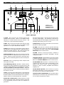
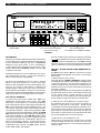
10 Rear Panel Description
15 14 13 12 11 10 9
1 2 3 4 5 6 7 8
1) CONV - This connector is the antenna input to the
optional VHF Converter. Attach a 50 OHMS nominal
impedance coaxial feed line from the antenna. This
connector accepts a standard PL-259 plug.
2) ANT 1 - This connector is used when attaching receiving
antennas with coaxial feed lines of 50 OHMS nominal
impedance. Accepts a standard PL-259 plug.
3) ANT 2 - This connector can be used to attach either a
low impedance (50 OHMS nominal) or high impedance
(500 Ohm nominal) antenna. The center clip is ground
and its connection should be as short as possible.
4) EXT 11-16 VDC IN - This connector is used for powering
the receiver from an external DC source such as a car
battery. Observe proper polarity when attaching wires.
This connector is internally protected from reverse polar-
ity.
5) DC Fuse - This is a 2 ampere type T fuse. Replace with
same type and rating.
6) AC LINE Voltage Selector - This switch is used to select
the proper line voltage setting for your particular area. BE
CERTAIN OF THE OPERATING VOLTAGE BEFORE CONNECT-
ING THIS RECEIVER TO THE MAINS SOURCE. Also, the
proper mains fuse and line cord may need to be installed.
See items (7) and (8).
7) Fuse - Check for proper fusing prior to connecting this
receiver to the mains source (see page 4). Fuse is 5x20 mm
SLO-BLO®, T400 mA for nominal 115/127 VAC operation;
T200 mA, 250V for nominal 220/240 VAC operation.
8) Power Line Cord Receptacle - This receptacle accepts
a three-wire power cable. When the cable is connected
to an appropriate power line outlet, the instrument is
grounded.
This unit is shipped with a cord intended for nominal 115/
127 VAC mains supply. For operation of this unit on
nominal 220/240 VAC mains supply, use the proper cable
assembly approved by your local codes.
9) GND (Ground) - The earth ground wire connected here
should be as short as possible.
10) TIMER - This 5 pin din connector provides switching
contacts for on/off control of an external device such as
a cassette tape recorder. Refer to the CLOCK & TIMER
FUNCTIONS section of this manual.
11) MUTE - The RCA connector provides a method of
muting the receiver for use with a transmitter. Ground
center pin to mute.
12) Interface RS-232C - This 9 pin DB-9 connector provides
a standard RS-232C interface to a keyboard terminal.
Refer to the RS-232C INTERFACE section of this manual.
13) LINE AUDIO OUT - Both RCA connectors provide a
constant low level audio source independent of the
setting of the volume control. They are designed to
interface to tape recorders, CW/RTTY demodulators,
amplifiers, etc.
14) EXT (External Speaker) - This connector accepts a
standard 1/4" diameter, 2-circuit, (monaural) phone plug
for connection of a 4-8 ohm external speaker.
15) Speaker Switch (INT/BOTH/EXT) - This 3 position switch
allows selection of internal only, both internal and exter-
nal, or external only speaker outputs.
FIGURE 6 REAR PANEL
A N T 2
CONV
ANT 1
50
50
50 GND 500
EXT 11 - 16 VDC IN
- +
108-
132V
90-
110V
216-
264V
180-
220V
W A R N I N G
RISK OF ELECTRIC
SHOCK DO NOT OPEN
RISQUE DE CHOC
ELECTRIQUE NE PAS OUVRIR
AVIS
CAUTION: - RISK OF FIRE -
REPLACE FUSE AS MARKED AFTER
DISCONNECTING UNIT FROM AC LINE.
ATTENTION:- RISQUE D'INCENDIE -
REMPLACEZ FUSIBLE DU TYPE INDIQUÉ
APRÉS DEBRANCHER DU SECTEUR.
INT EXT
BOTH
EXT OUT OUT MUTE
SPEAKER
LINE AUDIO
INTERFACE
RS - 232C
DC
AC
DISCONNECT FROM
SUPPLY BEFORE
CHANGING RANGES
WARNING
40 WATTS 50/60 Hz
100VAC 400 mA
120VAC 400 mA
200VAC 200 mA
240VAC 200 mA
TYPE T
GND
TIMER
MADE IN U. S. A.
BY ®
4
2A
TYPE T

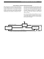
MUTE OPERATION OF THE R8B COMMUNICATIONS RECEIVER
The mute line does not disconnect the antenna. Older
Drake equipment required the mute line to be grounded
for receive. This receiver requires ground to mute.
When using the receiver with older Drake equipment,
an external relay is recommended to operate the
mute line. Sometimes this may be accomplished by
using a spare set of relay contacts on the antenna
switch-over relay.
If you are not operating a linear amplifier, you can use
the vox relay contacts to provide control of the re-
ceiver muting. Simply connect the two pin jack or RCA
phono socket of the AC-4, PS-75, PS-7, power supply to
the mute jack on the R8B.
When using this receiver with an external transmitter, it
is often desirable to be able to externally mute the
receiver during transmission. The receiver provides this
external control by use of the "MUTE" connector
located on the rear panel. Grounding the center pin
of this connector forces the AGC circuitry to shut down
all RF/IF stages, thus quieting or muting the receiver.
Mute Operation of the Receiver 11
ANTENNA COAX
ANTENNA RELAY CONTROL
ANTENNA RELAY
e.g. DOW-KEY,
ETC.
R8B RECEIVER
ANTENNA COAX
TRANSMITTER
OR
MUTE CABLE
FIGURE 7 SUGGESTED HOOKUP FOR MUTE OPERATION

BW
AUTO
6.0 4.0
2.3 1.8
0.5
MODE
AM SYNC
LSB USB
CW FM
RTTY
SCAN
MEM
LIST
A-B
SEEK
TIME
CARR
MEM
TUNE
VFO A = B
A = B
PRE ATTN
ANT 1 2 VHF
AGC S F
NOTCH
NB N W
NAME
12 ON OFF
TIMER
STEP
CLK/FREQ
LOCK
F
TUNE
SCAN
NOTCH TONE
SCAN
MEM
6.0
4.0
AM/
SYNC
FM
2.3
1.8 LSB USB
0.5
AUTO CW RTTY
BANDWIDTH
MODE
LIST
2
A - B
3
SEEK
4
TIME
5
CARR
6
CLK
7
LAMP
8
BEEP
9
F
DEL
0
V M
M V
SQUELCH
PASSBAND
OFFSET
VOL RF
MIN
0
-
+
R8B Communications Receiver
1 3 5 7 9 20 40 60
S UNITS DECIBLES
SIGNAL
M/KHz
MEM
1
CLR
kHz
MHz
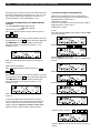
12 Getting Started
TONE
CENTERED
NOTCH
CENTERED
VOLUME
COUNTER-CLOCKWISE
FIGURE 8
SQUELCH
COUNTER-CLOCKWISE
PASSBAND OFFSET
CENTERED
RF GAIN
CLOCKWISE
GENERAL OPERATING INFORMATION
This receiver is easy to use. Please take a few moments to
read through this section and familarize yourself with
general operating information.
MICROPROCESSOR RESET
A power-up reset is activated each time the unit is
connected to an AC or DC power source. This may be
confirmed by the front panel display illuminating all
annunciators for 3 seconds, followed by the clock display.
If, for any reason, the receiver display or operation
becomes confused or a ‘PWRFAIL’ message is displayed,
unplug the receiver from the power source and
reconnect. Normal operations of the receiver are halted
in the ‘PWRFAIL’ mode. Note: Any programmed memory
locations will NOT be lost under a power-up reset or under
a ‘PWRFAIL’ mode due to the memory design of the
receiver.
BEEP TONES
The receiver responds to all button depressions with an
audible beep. They are as follows:
1 short tone for any button depression.
1 long, high tone when programming in memory mode.
1 long, low tone for any illegal button depression.
GETTING STARTED
1. Please refer to FIGURE 8 and adjust controls as shown.
2. Press the (power) button.
3. Press VFO button to select VFO A.
4. Press
F
button followed by the ANT button to select
desired antenna input.
5. Press one of the MODE buttons to select the desired
mode of reception. Press the AUTO (bandwidth) button
for automatic bandwidth selection with mode change or
press one of the BANDWIDTH buttons to select the desired
IF Bandwidth.
AUTO MODE, and the Default BANDWIDTH/STEP/AGC Set-
tings
If the AUTO mode is selected, the default Bandwidth, Step
and AGC setting are automatically recalled when the
mode is changed. These defaults are user program-
mable. To set the default, turn AUTO off (press the AUTO
button until AUTO is extinguished in the display area). Set
the Bandwidth, Step and AGC as desired for the defaults.
Press and hold the corresponding MODE button for which
the defaults are being set. A memory beep will indicate
that the defaults have been stored. Repeat the above
procedure for all modes that are to be programmed.
Once the defaults are programmed, and the AUTO mode
is selected, changing modes will recall the user pro-
grammed BANDWIDTH, STEP and AGC settings.
6. Check that 'SPEAKER' switch on rear panel is on desired
setting.
7. Adjust VOLUME (VOL) control for desired level.
Adjust SQUELCH control fully counterclockwise. Adjust RF
GAIN control fully clockwise.
Press the
F
button followed by
M V
M/KHz
to set frequency
entry units.
8. Press the CLK/FREQ button as required, to display
frequency. Use the numeric keypad to enter frequency,
in MHz or kHz, as indicated, directly or use the
or
tuning buttons to rapidly tune near a frequency, then fine
tune with the tuning knob.
FREQUENCY STEP SELECTION
TUNING WHEEL STEPS
The receiver can be programmed to tune in three differ-
ent resolutions (steps) with the corresponding display
readout.

The three choices are as follows:
A) 1 kHz display readout (tuning in 1 kHz steps).
Used for fairly rapid frequency search.
B) 100 Hz display readout (tuning in 100 Hz steps).
Used for tuning AM and FM signals.
C) 10 Hz display readout (tuning in 10 Hz steps).
Used for tuning SSB, CW, or data signals.
The step size may be programmed per mode. The re-
ceiver, as shipped from the factory, has step sizes pro-
grammed as shown in Table 2 below:
To change the step, press the
F
button followed by the
STEP function line button.
To reset the receiver to the factory settings for STEP size,
AGC setting, BANDWIDTH, etc.:
Press the POWER button to turn the receiver off. Press the
CLR
button and hold while pressing the POWER button to
turn Power on. After three seconds, the receiver will reset.
The tuning wheel incorporates variable rate tuning. The
faster the tuning wheel is rotated, the greater the fre-
quency change per tuning wheel revolution.
BUTTON STEPS
The
button increases and the button de-
creases the frequency by fixed steps with each depres-
sion as programmed. Pressing and holding either button
will allow continuous stepping up or down as long as the
button is depressed. The fixed steps are as follows:
To tune in 100 kHz steps, press the
F
button. With the
F
displayed, press the / buttons, as desired,
to tune in 100 kHz increments. Note that, regardless of the
/ button step increments, the display always
indicates the programmed tuning resolution (step) avail-
able by using the tuning wheel at any frequency.
DUAL VFO's
A) VFO A/VFO B
Two VFOs (A and B) are provided on the receiver. Selec-
tion is made with the VFO function key. Each VFO can be
set to any frequency and act as a temporary memory
channel.
Getting Started, continued 13
For example, suppose you want WWV at 10 MHz in VFO B
while using VFO A to tune other frequencies.
Press: VFO to select B
Press: AM mode button
Press:
MEM
1
DEL
0
CLR
CLR
- WWV is now stored in VFO B.
Press: VFO to select A
Tune other frequencies with VFO A. To recall WWV, press
VFO function button. NOTE: See 'DIRECT FREQUENCY EN-
TRY' section below for explanation of second
CLR
entry.
B) A=B
This function is used to transfer the frequency of the active
VFO into the inactive VFO. This is handy if you are tuning
and would like to temporarily hold a certain frequency as
you continue tuning. For example, suppose you are
tuning in VFO B and come across a station at 4.5 MHz you
would like to occasionally check.
Press:
F
, then A=B. Equal (=) symbol now appears
between VFO A = B.
Continue tuning and recall station at 4.5 MHz anytime by
pressing the VFO button.
DIRECT FREQUENCY ENTRY
Direct keyboard entry of a frequency is possible using
numeric buttons 0-9 and decimal
CLR
allowing for rapid
frequency change. Pressing the button sequence
F
,
CLR
will cancel any frequency or memory channel num-
ber entry in progress and return the setting to its previous
state.
NOTE: With the optional VHF Converter installed, entering
a three digit frequency (in MHz) is possible after first
selecting
VHF
antenna.
Press: VFO to select VFO A or VFO B
TO ENTER FREQUENCY IN MHz:
Press:
F
,
M V
M/KHz
to select 'MHz' display mode if required.
Enter frequency in MHz beginning with the most signifi-
cant digit. You do not need to enter leading or trailing
zeros.
Examples:
1) 1.410 MHz - Press:
MEM
1
CLR
SEEK
4
MEM
1
CLR
2) 29.660 MHz - Press:
LIST
2
BEEP
9
CLR
CARR
6
CARR
6
CLR
The second depression of the decimal
CLR
button acts as
an 'Enter' and causes immediate response to the entered
digits. If you forget to press the decimal
CLR
button a
second time, the receiver will automatically do so for you,
but with a slight delay.
3) 700 KHz (= .70 MHz) - Press:
CLR
CLK
7
. After 3 second
pause, frequency will be entered.
TO ENTER FREQUENCY IN kHz:
Press:
F
,
M V
M/KHz
to select 'kHz' display mode if not already
selected. Enter frequency in kHz beginning with the most
significant digit, followed by a double depression of the
CLR
button. Example:
1) 700 kHz - Press:
CLK
7
DEL
0
DEL
0
CLR
CLR
Frequency will be immediately displayed. Attempting to
enter a frequency outside of the tuning range of the
receiver will cause the word ERROR to be displayed along
with the error beep to be heard. The receiver will then
return to the last displayed frequency.
Tuning and
Display Resolution (Hz)
10
100
Table 2
Mode
LSB, USB, RTTY, CW
AM, FM
Frequency Range
100-540 kHz
540-1800 kHz
1800-30,000 kHz
Step
5 kHz
AM mode: 10 kHz
(9 kHz if programmed)
Other modes: 5 kHz
5 kHz

14 Getting Started, continued
FRONT PANEL LOCK (UNLOCK)
First be sure the receiver is in the VFO mode, ( MEM or
SCAN not displayed). All button entries, display settings
and the large tuning knob can be locked if desired.
Press
F
LOCK to lock front panel. All analog control
knob functions, except tuning, will still remain operable.
Press
F
LOCK to unlock front panel if previously locked.
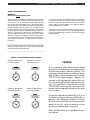
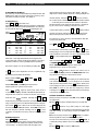
PASSBAND OFFSET OPERATION
When the PASSBAND OFFSET control is centered, the
receiver will properly position its IF passband with mode
change. Occasionally, an interfering signal will appear
above or below the desired signal. Rotating the PASS-
BAND OFFSET “+” or “-” will reduce or eliminate this
interfering signal by electronically shifting the receiver’s IF
passband. Refer to FIGURE 9. This shifting of the IF
passband also alters the audio quality. For example, if you
are receiving a signal in USB and rotate the PASSBAND
OFFSET control “-”, the audio will become low pitched.
Conversely if the control is rotated to the “+” position, the
audio will become high pitched. The results are reversed
in LSB; rotated “+” the audio becomes low pitched,
rotated “-” the audio becomes high pitched.
In AM, the PASSBAND OFFSET can enhance audio quality.
For example, with the PASSBAND OFFSET control at the
normal 12 o’clock position and the 6 kHz IF filter selected,
the maximum audio response will begin to roll off at 3 kHz.
If the PASSBAND OFFSET control is moved to one side or
the other, audio response exceeding 5 kHz is obtainable
thus enhancing fidelity. Try both offset directions to deter-
mine which side of the signal is least subject to any
possible adjacent signal interference. The PASSBAND
OFFSET control is also coupled to the synchronous detec-
tor (SYNCHRO) allowing the passband to be altered while
the detector is in use.
NOTCH OPERATION
Audio notch will nullify signals from 500 Hz at the counter-
clockwise setting of the control to 5kHz at the clockwise
setting. Adjust control to nullify an undesired signal.
AM SYNCHRONOUS DETECTOR OPERATION
For general tuning and listening, the normal AM detector
is best. It allows normal AM reception while providing the
capability to offset the IF passband without causing distor-
tion. If the received signal is experiencing severe fading as
is common on many SW and BC bands, the synchronous
Desired
Signal
PASSBAND OFFSET
CENTERED
Desired
Signal
Undesired
Signal
PASSBAND OFFSET
+
Undesired
Signal
PASSBAND OFFSET
-
Desired
Signal
FIGURE 9 PASSBAND OFFSET Operation
interference
from
adjacent station
CARRIER
LSB USB
Select LSB
to receive
this side
only
detector should be engaged. Make sure the main tuning
is set to within 1 kHz of the station’s transmitting frequency.
Adjust the PASSBAND OFFSET control and change band-
width as required to minimize any interference. Press AM/
SYNC to activate the synchronous detector. The word
SYNC is displayed following AM to indicate the synchro-
nous detector is selected and locked. SYNC will flash to
indicate that the detector is acquiring lock. This detector
provides a very powerful aid in reducing the severe audio
distortion that can occur during the time period when the
carrier of the received AM signal is cancelled or reduced
by propagation effects.
When the synchronous detector has been activated,
moving the main tuning will automatically switch the
receiver out of synchronous detection while the synchro-
nous detector re-aquires lock. The ‘SYNC’ annunciator
will flash briefly until lock is achieved. Also, moving the
PASSBAND OFFSET control while the synchronous detec-
tor is engaged, will cause the receiver to momentarily
switch out of synchronous detection while the synchro-
nous detector re-aquires lock. The ‘SYNC’ annunciator
will flash briefly until lock is achieved.
The detector also permits selectable tuning to either the
upper or lower sideband portion of an AM signal. Since
most all AM (LW, MW and SW) broadcasting generally
uses double-sideband transmission, detection of either of
the two sidebands results in full reception of the transmit-
ted information. The selectable sideband tuning and
detection not only aids reception by permitting tuning to
the stronger or less distorted sideband, but also permits
rejection of the sideband nearer to the interfering signal(s).
For Example:
The synchronous detector will lock to the strongest signal
that is within the IF passband when it is activated. Most of
the time, the strongest signal will be the carrier of the
desired signal. First, be sure the main tuning is set to within
1 kHz of the desired station’s transmitting frequency. Press
the
AM/
SYNC
button to activate synchronous operation. If
adjacent channel interference or any other undesired
signal is sufficiently strong, the synchronous detector may
lock to it instead. In that case, press the
AM/
SYNC
button to
turn the synchronous detector off and repeat the tuning
process. For severe cases of fading, set the audio band-
width to 4 kHz. If interference is present, press the LSB or
USB button, with the AM SYNC active, to select the side-
band with the least interference. If the interference is
sufficiently severe to prevent reception, select a narrower
IF bandwidth and retune to the desired signal. After
reception is obtained, select a wider bandwidth and/or
alternate sideband if desired. When AM/SYNC has been
activated, moving the main tuning knob will cause the
SYNC circuit to momentarily disengage (indicated by
‘SYNC’ flashing), then back on again when tuning has
stopped. AM SYNC will not operate properly on intermit-
tent transmissions such as those encountered on CB radio
bands, for example. For those types of transmissions, use
the AM mode. Press the
AM/
SYNC
button to turn the synchro-
nous detector off before selecting LSB or USB modes.
Page is loading ...
Page is loading ...
Page is loading ...
Page is loading ...
Page is loading ...
Page is loading ...
Page is loading ...
Page is loading ...
Page is loading ...
Page is loading ...
Page is loading ...
Page is loading ...
Page is loading ...
Page is loading ...
Page is loading ...
Page is loading ...
Page is loading ...
Page is loading ...
Page is loading ...
Page is loading ...
Page is loading ...
Page is loading ...
Page is loading ...
Page is loading ...
-
 1
1
-
 2
2
-
 3
3
-
 4
4
-
 5
5
-
 6
6
-
 7
7
-
 8
8
-
 9
9
-
 10
10
-
 11
11
-
 12
12
-
 13
13
-
 14
14
-
 15
15
-
 16
16
-
 17
17
-
 18
18
-
 19
19
-
 20
20
-
 21
21
-
 22
22
-
 23
23
-
 24
24
-
 25
25
-
 26
26
-
 27
27
-
 28
28
-
 29
29
-
 30
30
-
 31
31
-
 32
32
-
 33
33
-
 34
34
-
 35
35
-
 36
36
-
 37
37
-
 38
38
-
 39
39
-
 40
40
-
 41
41
-
 42
42
-
 43
43
-
 44
44


Ask a question and I''ll find the answer in the document
Finding information in a document is now easier with AI
Related papers
Other documents
-
 Sangean Electronics Sangean PT-80 User manual
-
Intermatic ET100 SERIES Programming Manual
-
-
Sangean PAKKET505 Datasheet
-
GPX KL858S User manual
-
-
-
AOR AR-ONE Owner's manual
-
-
Curtis KCR2610 User manual
