Page is loading ...

Cancels: OM02-56 OG-PHIZ-01
1/03
NOTE TO INSTALLER:
This manual should be left with the equip-
merit owner.
Model PHIZ Packaged Heat Pump Unit

WELCOME TO EFFICIENT YEAR-ROUND COMFORT
Congratulations on yore" excellent choice and sound invest-
ment in home comfort!
Your new heat pump represents both the latest in engineer
ing development and the cuhnination of many years of
experience fl'om one of the most reputable manufacturers of
comfort systems.
Your new unit is among the most reliable home comfort prod
ucts available today. To assure its dependability, spend just a
few minutes with this booklet now. Learn about the opera-
tion of your heat pmnp and the small amount of mainte-
nance it takes to keep it operating at its peak efficiency.
With minhnal care, your heat pump will provide you and your
family with satisfying home comfort -- both now and for years
to corne.
IMPORTANT FACTS
To better protect your investment and to eliminate unneces-
sary service calls, familiarize yore'self with the following facts:
• Your treat pump system should never be operated without
a clean air flter properly installed. Plan to inspect the fil-
ter periodically. A clogged air filter will increase operating
costs and shorten the life of the unit.
• Supply-air and return-air registers should not be blocked.
Drapes, ftxrniture, and toys are some of the items corn
monly found obstructing grilles. Restricted airflow lessens
the unit's efficiency and life span.
• Outdoor units must have unrestricted airflow. Do not cover
the trait, lean anything against it, or stand upon it. Do not
allow grass clippings, leaves, or other debris to accumu
late arotmd or on top of the unit. Maintain a 12-in. mini-
mum clearance between the outdoor unit and tall grass,
vines, shrubs, et cetera.
• Your multipurpose indoor thermostat is the control center
fox"your heat pump system. You should familiarize your-
self with its proper operation. Attempting to control the
system by other means -- for instance, switching the elec-
trical supply power ON and OFF may cause damage to
the unit.
• Thermostat '_jiggling" causes rapid-cycling, which is poten-
tially damaging to the compressor. Do not move the tem-
perature selector on the thermostat fox"any reason for at
least 5 minutes after the compressor has shut off.
• You may find that you can maintain greater personal com-
fort by running the fan continuously. "Air pockets" can form
due to the structure of the building, placement of regis
ters, et cetera. These air pockets may be too cool or warm
fox"your liking. Continuous fax] operation minimizes any
temperature differences. Also, systems equipped with elec-
tronic air cleaners and/or humidifiers offer the added ben-
efits of having the air continuously cleaned year-round, and
humidified during the winter season.
• Your heat pmnp will remove humidity fl'om your home dur
ing the cooling season. After a few minutes of operation,
you should be able to see water" trickle from the conden-
sate drain. Check this occasionally to be sure the drain sys-
tem is not clogged. Of course, do not expect to see much
drainage if you live in a very dry climate.
OPERATING YOUR HEAT PUMP
The operation of your heat pump system is controlled by the
indoor thermostat. You simply adjust the thermostat and it
maintains the indoor" temperature at the level you select. Most
thermostats for" heat pmnp systems include temperature con-
trol selector, FAN switch, and SYSTEM switch. EMER-
GENCY HEAT control is usually provided with the SYSTEM
switch.
The temperature control selector is a dial or button(s) that al-
lows you to establish the temperature that you wish to main-
tain for your personal comfort. Some thermostats possess two
temperature control selectors: one fox"setting the tempera-
ture desired during the cooling cycle, and one to set the heat
ing operation temperature. Typical settings are 78 degrees
Fahrenheit for cooling and 68 degrees for heating.
The FAN switch offers two options fox" controlling the
blower: AUTO and ON. When set to AUTO, the blower will
run during the time the heat pump is operating. When the
EAN switch is set at the ON position, the blower will run
continuously.
Typically, the SYSTEM switch on your thermostat offers the
following selections: COOL, OFF, and HEAT. Your thermo
star may also have another selection, AUTO. The heat pmnp
will not operate when the SYSTEM switch is set at the OFF
position. With the SYSTEM switch set at COOL, your heat
pump will operate in its cooling mode when the indoor tern-
perature rises above the level that you wish to maintain. With
the SYSTEM switch set at the HEAT position, your heat pump
will provide warmth whenever the indoor temperature falls
below the level that you have selected.
The AUTO selection found on some thermostats provides for
automatic changeover between cooling and heating cycles. With
the SYSTEM switch set in the AUTO position, the cooling
mode is activated when the indoor temperature rises above
the thermostat cooling temperature setting, or the heating
mode will be activated when the indoor temperature drops
below the thermostat setting for" the heating cycle.
Depending on your winter heating needs, your home comfort
system may include supplementary electric resistance heat.
If it does, your system will turn on electric resistance heat
only as necessary to meet your heating needs during defl'ost
cycles or when outdoor temperatures are low. In the event of
a heat pmnp malfimction, you can use the EMERGENCY HEAT
setting on your thermostat to manually select electric resis
tance heat. Heat pump heating is deactivated when EMER
GENCY HEAT is selected. Because electric resistance heat
consumes more electricity than the heat pump's normal heat-
ing mode, selecting EMERGENCY HEAT will result in higher
electricity costs. If it becomes necessary to use EMER-
GENCY HEAT to provide heat, call your dealer fox"service as
soon as it is practical.
See your thermostat owner's manual for" additional
information.
2

I. COOLINGCYCLE
Whenoperatinginthecoolingcycle,yourheatpumpwillrun
untiltheindoortemperature is lowered to the level you have
selected. On extremely hot days, your heat pump will run for
longer periods at a time and have shorter" "off' periods than
on moderate days.
The following are typical conditions that add extra heat and/or
humidity to your home. Your heat pump will work longer to
keep your home comfortable under these conditions:
• Entrance doors are frequently opened and closed
• Laundry appliances are being operated
• A shower is running
• More than the usual number of people are present in the
home
• More than the normal number of electric lights are in use
• Drapes are open on the sunny side of the home
II. HEATING CYCLE
With the SYSTEM switch of your indoor thermostat set to
the HEAT position, the treat pump will operate in its heating
mode until room temperature is raised to the level you have
selected. Of course, the heating unit will have to operate for"
longer periods to maintain a comfortable environment on colder
days and nights than on moderate ones.
A. Defrost Cycle
When your heat pump is providing heat to your home and
the outdoor temperature drops below 45 degrees Fahrenheit,
moisture may begin to fl'eeze on the surface of the outdoor
coil. If allowed to build up, this ice would impede airflow across
the coil and reduce the amount of heat absorbed fl'om the out-
side air. So, to maintain energy efficient operation, your heat
pump has an automatic defrost cycle.
The defrost cycle starts at a preset time interval of 30 rain
utes. Defl'ost will start at the preset time only if the ice is
sufficient to interfere with normal heating operation.
After the ice is melted from the outdoor coil, or after a maxi-
mum of 10 minutes in the Defrost mode, the unit will auto
matically switch back to normal heating operation.
Do not be alarmed if steam or fog appears at the outdoor unit
during the defl'ost cycle. Water vapor fl'om the melting ice
may condense into a mist in the cold outside air.
B. Emergency Heat
The EMERGENCY HEAT setting on your thermostat refers
to any supplementary heating appliance that may be in
cluded in your home comfort system. Operation of the EMER-
GENCY HEAT source may be required if heating demands
exceed the capacity of the heat pump, or if the heat pump
malfunctions.
The word Emergency will show on the display of the thermostat
if the mode button is toggled/pushed from NORMAL to the EMER-
GENCY HEAT setting. This indicates that the heat pump is
off and the supplemental heating appliance is selected for"
operation.
The word AUX HEAT will be displayed under normal operation
when the second stage of heat is operating.
• Do not operate your unit in the heating mode when outdoor
telnperatures are above 66°F unless you set your thermostat
to emergency heat mode.
Z7
During the heating season, switch to EMERGENCY HEAT if
the electricity to your outdoor unit is off for more than
30 minutes for any reason (i.e., power outage). Leave the switch
in the EMERGENCY HEAT position for an amount of time
equal to that during which the power was off. It is not nec-
essary to exceed 12 hours. If you cannot determine how long
the power has been off, leave the switch in the EMER-
GENCY HEAT position for"8 hours.
PERFORMING ROUTINE MAINTENANCE
With the proper maintenance and care, your heat pump will
operate economically and dependably. Maintenance can be ac
complished easily by referring to the following directions. How-
ever, before performing maintenance, consider these impor-
tant safety precautions:
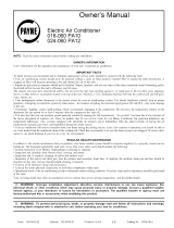
MAIN
ON
--3--

CHECK THE AIR FILTER
A dirty air filter will cause excessive strain on the compres-
sor and blower motor. This can cause the components to
overheat and automatically shut down. In the extreme, the
components will fail and need to be replaced. To avoid
inefficient or failed operation of your unit, CHECK THE
FILTER(S) EVERY 3 TO 4 WEEKS. Replace filter(s) when
necessary, or clean the filter(s) if you have the reusable type.
Disposable filters should be replaced by similar, new filters
of the same dimensions.
Reusable, permanent filters should be washed in a solution
of cold water and mild detergent, then rinsed and thoroughly
dried. THE FILTER MUST BE COMPLETELY DRY BE
FORE BEING REINSTALLED. To avoid prolonged shut
down of your unit while a filter is drying, you should have an
extra filter on hand. This would allow you to rotate between
the two with minimal downtime for your comfort system. Ex
tra filters may be purchased fl'om your dealer.
The filter(s) and filter rack for a packaged system are sup-
plied and installed by the contractor or dealer. Typically, the
filter(s) and rack are located in the return-air duct at the out-
door unit or behind the return air grille(s). Have your dealer
show you the location of your filter(s) and the procedures for"
removal and replacement.
If you have any questions about the removal and/or cleaning
of your filter(s), contact your dealer for" assistance.
If grass clippings, leaves, shrubbery, and debris are kept away
from the unit, minimal care should be sufficient to keep the
system flmctioning properly. However, if the outdoor coil be-
comes dirty, use a brush or vacuum cleaner and soft brush
attachment to clean the exterior surface. If dirt is trapped
deep in the coil, contact your dealer for" service.
UNIT SUPPORT
Your packaged unit should be maintained at a level position.
If its support should shift or settle so that the unit is no longer
level, you should correct the condition. Relevel it promptly to
assure condensate drainage out of the unit. If you notice that
water or ice collects beneath the unit, arrange for it to be drained
away from the unit.
BEFORE YOU REQUEST A SERVICE CALL
BEFORE YOU CALL FOR SERVICE, CHECK FOR
THESE EASILY SOLVED PROBLEMS:
Check the indoor and outdoor disconnect switches. Verify that
circuit breakers are ON or that fllses have not blown.
Check for sufficient airflow. Check the air filter(s) for any ac
cumulations of dirt. Check for blocked return-air or supply-
air grilles. Be sure grilles are open and unobstructed.
Check the settings on your indoor thermostat. If you desire
cooling, see that the temperature control selector is set below
room temperature and the SYSTEM switch is on the COOL
or AUTO position. If you require warmth, be sure the tern-
perature control selector" is set above room temperature and
the SYSTEM switch is at HEAT or AUTO. The FAN switch
should be set at ON for continuous blower operation or AUTO
if you wish the blower to flmction only while the unit is op
erating.
If your comfort system still fails to operate, contact your ser
vicing dealer for troubleshooting and repairs. Specify your ap
parent problem, and state the model and serial numbers
of your equipment. (You should have them recorded on this
page.) With this information, your dealer may be able to offer
helpflll suggestions over the phone, or save valuable time
through knowledgeable preparation for the service call.
REGULAR DEALER MAINTENANCE
In addition to the routine maintenance that you perform, your
home comfort system should be inspected regularly by a prop-
erly trained service technician. The inspection (preferably each
year, but at least every other year) should include the
following:
• Routine inspection if air filter(s). Replacement or cleaning
as required.
• Inspection and cleaning of tire blower wheel, housing, and
motor. Service should include proper lubrication of these
conlponei]ts.
• Inspection and, if required, cleaning of indoor" and outdoor
coils.
• Inspection of the indoor coil drain pan, plus the drain line.
Service should include cleaning if required.
• A check of all electrical wiring and connections.
• A check for secure physical connections of individual com-
ponents within units.
• Operational check of the system to determine actual work
ing condition. Necessary repair and/or adjustment should
be performed at this time.
WARRANTIES
The warranty is located at the back of this book. Be sure to
read the warranty careflrlly to determine the coverage for your
unit.
FOR THE RECORD
Record the model, product, and serial numbers of your new
equipment in the spaces provided below. This information,
along with the other ready reference facts requested below,
will be necessary should you ever require information or
service.
INSTALLATION DATA
Date Installed
Dealer Name
Address
City
State
Telephone
UNIT DATA
Product No.
Model No.
Serial No.
Heater, if applicable:
Part No.
Kilowatt Rating
Zip
© 2003 Payne Heating & Cooling PO Box 70, Indianapolis, IN 46206 -4- og-phlz-01 53PH-1Z6
/