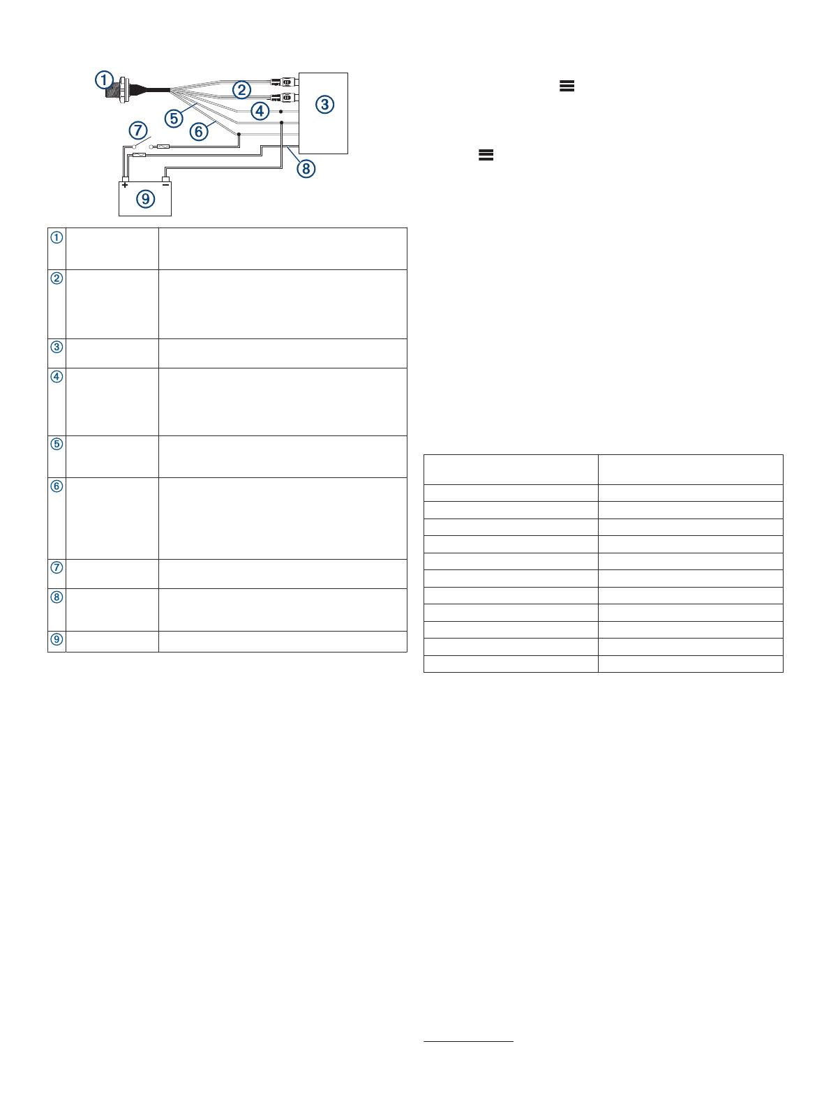
Fusion MS-FHM Installation guide

Type
Installation guide

Fusion MS-FHM is a handheld microphone designed for use with compatible Fusion stereos. It allows you to make announcements or sing along to your favorite tunes, and it will automatically switch the stereo to the AUX1 source when you press the button. The microphone has a frequency response from 100 Hz to 4 kHz, a maximum output of 1 Vrms, and a gain of +18 ± 0.5 dB. It is water-resistant rated to IPX7 standards and has a power and audio cable length of 60 cm (23 5/8 in.).

Fusion MS-FHM is a handheld microphone designed for use with compatible Fusion stereos. It allows you to make announcements or sing along to your favorite tunes, and it will automatically switch the stereo to the AUX1 source when you press the button. The microphone has a frequency response from 100 Hz to 4 kHz, a maximum output of 1 Vrms, and a gain of +18 ± 0.5 dB. It is water-resistant rated to IPX7 standards and has a power and audio cable length of 60 cm (23 5/8 in.).

®
Handheld Microphone
WARNING
Failure to follow these warnings and cautions could result in
personal injury, damage to the vessel, or poor product
performance.
See the Important Safety and Product Information guide in the
stereo box for product warnings and other important information.
This device must be installed according to these instructions.
Disconnect the vessel's power supply before beginning to install
this product.
CAUTION
To avoid possible personal injury, always wear safety goggles,
ear protection, and a dust mask when drilling, cutting, or
sanding.
NOTICE
When drilling or cutting, always check what is on the opposite
side of the surface to avoid damaging the vessel.
You must read all installation instructions before beginning the
installation. If you experience difficulty during the installation,
contact Fusion
®
Product Support.
Tools Needed
Pencil
Drill
16 mm (
5
/
8
in.) drill bit
2.5 mm (
3
/
32
in.) drill bit
16 mm (
5
/
8
in.) socket or wrench
Phillips screwdriver
Marine sealant (optional)
Installing the Connector Mount
Before drilling a hole to mount the connector, you should verify
that the microphone cable is long enough to reach the back of
the stereo and the connector mounting location.
You can use the included hardware to mount the connector on
the end of the microphone cable onto the dashboard or other
mounting surface.
1
Orient the mounting plate with the flat edge of the central
hole pointing to the left, and place it on the surface where
you plan to mount the connector.
If you orient the plate with the flat surface pointing to any
direction other than the left, the microphone cable will not
point downward when you connect it.
2
Using the mounting plate as a template, trace the cable
hole in the center of the mounting plate, and mark the screw
locations.
3
Set the mounting plate aside.
Do not drill through the mounting plate.
4
Using a 16 mm (
5
/
8
in.) drill bit, drill the center cable hole
in the mounting surface.
5
Using a 2.5 mm (
3
/
32
in.) drill bit, drill the pilot holes.
6
Place the rubber gasket between the mounting plate and
the mounting surface.
7
Using the included screws, attach the mounting plate and
gasket to the mounting surface.
8
Route the microphone cable to the back of the stereo and to
the connector mount.
9
Feed the connector through the back of the mounting
surface.
10
Secure the connector and weather cap to the mounting
plate using the nut .
NOTICE
If you disconnect the microphone from the connector, you
should secure the weather cap to avoid corrosion on the
connector contacts.
Mounting the Microphone Hanger
NOTICE
If you are mounting the bracket on fiberglass with screws, it is
recommended to use a countersink bit to drill a clearance
counterbore through only the top gel-coat layer. This will help to
avoid cracking in the gel-coat layer when the screws are
tightened.
You can mount the microphone hanger in a convenient location
near the radio.
1
Select a mounting location for the microphone within reach of
the microphone cable.
2
Using the microphone hanger as a template, mark the pilot
holes.
3
Drill the mounting holes using a 3 mm (
1
/
8
in.) drill bit.
4
Secure the microphone hanger to the mounting surface using
the included screws .
GUID-1CD23792-2CC2-4768-B1BD-D1E11B6C23D8 v1June 2020
Connection Diagram
Microphone
connector
You can securely mount the microphone
connector in an accessible location (Installing the
Connector Mount, page 1).
RCA connectors You must connect these to the AUX IN
connector on the stereo wiring harness.
If the stereo has more than one AUX IN
connector, you must connect to the AUX1
connector.
Compatible
stereo
TELEMUTE You must connect the bare wire from the
microphone cable to the TELEMUTE wire on the
stereo wiring harness if you want the microphone
to change the source when activated(Operating
the Handheld Microphone, page 2).
Negative (-)
power
connection
For the best results, you should connect the
negative (-) wire from the microphone to the
same negative (-) terminal as the stereo.
Positive (+)
ignition power
connection
You should connect the positive (+) wire from the
handheld microphone to the ignition wire from
the stereo to avoid draining the battery.
You must route the combined positive (+) and
ignition wires through a 3 A fuse before
connecting to the ignition or manual switch.
Ignition or
manual switch
The ignition or manual switch turns on the stereo
and microphone.
Stereo power
positive
connection
You should not connect the positive (+) wire from
the microphone to the constant power cable from
the stereo to avoid draining the battery.
Power source
Operating the Handheld Microphone
You must configure the stereo before you can operate the
handheld microphone (Configuring the Fusion Stereo for the
Handheld Microphone, page 2).
You can use the handheld microphone from any source on the
stereo. If the source is set to anything other than AUX1 when
you hold the microphone button, the source switches to AUX1
automatically, and switches back to the original source after you
release the button.
NOTE: You should stand behind the speakers that will be
broadcasting from the microphone. If you are standing in front of
the speakers, the microphone will pick up the broadcast and
cause feedback.
1
Select any source on the stereo.
NOTE: If you set the stereo to the AUX1 source, there is no
sound until you hold the microphone button and speak.
2
Hold the button on the side of the microphone and speak into
it.
NOTE: If the stereo is playing music from a source, you
should wait about 2 seconds before speaking to avoid cutting
off the beginning of your announcement.
3
After you have finished speaking, release the button.
If the stereo was playing music from a source before you held
the button, the stereo switches back to that source
automatically.
Configuring the Fusion Stereo for the Handheld
Microphone
1
On the stereo, select > SETTINGS > TELEMUTE.
2
Select AUX1 to fill the check box.
The stereo will now change to the AUX1 source when you
hold the button on the side of the handheld microphone.
3
Select > SETTINGS > SOURCE > AUX1.
4
Select PARTYBUS ENABLED to clear the checkbox.
When you clear the checkbox, the AUX1 source is no longer
available for streaming over the Fusion PartyBus
network. It
is recommended to disable network streaming for the
microphone source to avoid feedback caused by the slight
delay present when streaming.
Adjusting the Gain of the Handheld Microphone
If the volume of the microphone broadcast is too loud or too
quiet in relation to the other sources on the stereo, you can
adjust the gain level for the AUX1 source.
1
On the stereo, change the source to AUX1.
2
Adjust the gain to raise or lower the microphone volume in
1 db steps.
A positive (+) gain setting increases the microphone volume,
and a negative (-) gain setting decreases the microphone
volume.
Specifications
Microphone dimensions (H×W×D) 88 × 60 × 34 mm (3
1
/
2
× 2
3
/
8
×
1
11
/
32
in.)
Power and audio cable length 60 cm (23
5
/
8
in.)
Frequency response From 100 Hz to 4 kHz
Microphone weight 250 g (8.75 oz)
Output (max.) 1 Vrms
THD+N (Vo = 1 Vrms, 1 kHz) Less than 0.1% Vrms
Gain +18 ± 0.5 dB
Load impedance (min.) 10k Ohm
Operating voltage From 10.5 to 32 Vdc
Current (at 14.4 Vdc) 0.005 A
Fuse (not included) 3 A
Water rating IEC 60529 IPX7
1
© 2020 Garmin Ltd. or its subsidiaries
Garmin
®
, the Garmin logo, Fusion
®
, and the Fusion logo, are trademarks of Garmin Ltd.
or its subsidiaries, registered in the USA and other countries. These trademarks may not
be used without the express permission of Garmin.
M/N: A13014
1
For more information, go to garmin.com/waterrating.
© 2020 Garmin Ltd. or its subsidiaries www.fusionentertainment.com
  • Page 1 1
  • Page 2 2

Fusion MS-FHM Installation guide

Type
Installation guide

Fusion MS-FHM is a handheld microphone designed for use with compatible Fusion stereos. It allows you to make announcements or sing along to your favorite tunes, and it will automatically switch the stereo to the AUX1 source when you press the button. The microphone has a frequency response from 100 Hz to 4 kHz, a maximum output of 1 Vrms, and a gain of +18 ± 0.5 dB. It is water-resistant rated to IPX7 standards and has a power and audio cable length of 60 cm (23 5/8 in.).

Ask a question and I''ll find the answer in the document

Finding information in a document is now easier with AI