Page is loading ...

AMERITRON RCS-12
INSTRUCTION MANUAL
116 Willow Road
Starkville, MS 39759 USA
662-323-8211
Version 3B
Printed in U.S.A.
AUTOMATIC
ANTENNA SWITCH
PLEASE READ THIS MANUAL BEFORE OPERATING THIS EQUIPMENT !
COPYRIGHT C 2005 AMERITRON

Ameritron RCS-12 Instruction Manual Automatic Antenna Switch
Contents
THE BASICS
Introduction......................................................................................................................................1
Features............................................................................................................................................1
Specifications...................................................................................................................................1
Overview..........................................................................................................................................2
Band Data Information .......................................................................................................2
Hot Switch Protection.........................................................................................................2
Front Panel.......................................................................................................................................3
Rear Panel........................................................................................................................................3
Installation
Powering the RCS-12 ......................................................................................................................4
Connection to Tower Mounted Relay Box......................................................................................4
Using the RCS-10 Relay Box.............................................................................................4
Using Other Relay Boxes ...................................................................................................4
Using Direct or Regulated Relay Voltage ..........................................................................5
Radio Interfacing .............................................................................................................................6
Icom....................................................................................................................................6
Yaesu ..................................................................................................................................7
Kenwood.............................................................................................................................7
Auxiliary Input.................................................................................................................................8
Auxiliary Output..............................................................................................................................8
Radio Key In....................................................................................................................................9
Amp Key Out...................................................................................................................................9
OPERATION
Manual Mode.................................................................................................................................10
Automatic Mode............................................................................................................................10
Saving Antenna Selections ...............................................................................................10
Erasing Antenna Selections ..............................................................................................10
APPENDICES
Setting Relay Switching Delay......................................................................................................11
Resetting the RCS-12.....................................................................................................................11
Troubleshooting.............................................................................................................................11
Technical Assistance......................................................................................................................11
List of Accessories.........................................................................................................................11

Ameritron RCS-12 Instruction Manual Automatic Antenna Switch
1
Introduction
Congratulations on your choice of the Ameritron RCS-12 Automatic Antenna Switch. The RCS-12 is
specially designed to give you automatic antenna switching with hands free operation. This unit also has
the flexibility to work with many different station configurations. Please read this manual thoroughly
before operating your RCS-12.
Features
Easy to Operate: The RCS-12 is straightforward and basic. Operate with ease in minutes!
Easy to Program: Automatic operation is easily accomplished, and is programmed much the same way
as the presets on the AM/FM receiver in your vehicle.
Compatibility: This antenna switch has been designed to use the band data output, on your radio, to
automatically switch antennas. This unit is compatible with most Icom, Yaesu, and Kenwood
transceivers. Some other radios are also compatible.
Versatile: The RCS-12 will work with the 5 and 8 position tower-mounted relay boxes from Ameritron.
However, the RCS-12 will work with any relays using up to 30VDC. Output formats can be 1 of 8, 3
line BCD, or 4 line BCD.
Transmitter Protection: The RCS-12 will not allow you to change antennas while you are transmitting.
A user programmable delay is used to give the relays time to fully open, so that your transmitter will be
completely protected against “Hot Switching.”
RCS-12 Specifications:
Input Voltage: +13.8V – 30V DC
Output (Relay) Voltage: +12V – 30V DC
Relay Output Format: 3 Line BCD, 4 Line BCD, or 1 of 8
Switchable Antennas: Up to 8
Dimensions: 7.5” x 8.25” x 2.75”

Ameritron RCS-12 Instruction Manual Automatic Antenna Switch
2
Overview
Band Data Information
The RCS-12 will operate with simple push-button operation in Manual mode. In Automatic mode, the
RCS-12 reads Band Output Data from the appropriate jack on the back of your transceiver(s). The RCS-
12 is designed to work with most Icom, Yaesu, and Kenwood transceivers. There are separate inputs for
each of these input types. Please read this manual carefully, because some older models of transceivers
may have a different output format than newer ones.
New Kenwoods: This category is for new Kenwoods that have a DB-9 connector for computer control.
Serial data is read from this port to get the band data.
Icom: Icom transceivers use a “step voltage” to output band data. A voltage from 0 - 8 Volts is output
from the band data pin on the accessory jack.
Yaesu, older Kenwoods, and others: This category will cover most radios besides Icoms and newer
Kenwoods. Yaesu outputs band data in a 4 line BCD format. Many other transceivers use this standard.
The RCS-12 does not actually care what binary number the BCD data represents, it will match the
“pattern” with whichever antenna you preset it to.
If your transceiver is not one of the above listed, please check in your instruction manual to see if it has a
BCD output that is similar to that of Yaesu.
Also note that sometimes the same output will be used for more than 1 band. For example, Icom uses the
same output for 15 and 17 meters, and 10 and 12 meters.
Hot Switch Protection
The RCS-12 will fully protect your transmitter and antenna system from hot switching. This feature will
prohibit you from switching antennas while your transmitter/amplifier is transmitting. Hot Switch
protection is very useful during contesting ,when antennas may need to be switched often. This feature
also includes a user programmable delay that will allow sufficient switching time for the tower-mounted
relays that you are using. This delay can be programmed from 10ms to 1s, default 50ms. See page 10 for
more details. The hot switch protection sequence works as follows, assuming an antenna has already
been selected.
Transmit, unkey→ Delay 10ms→ Select Antenna → Relay Switching Delay (10ms – 1s) → Transmit Again

Ameritron RCS-12 Instruction Manual Automatic Antenna Switch
RCS-12 Front Panel
AUTOMATIC ANTENNA SWITCH
RCS-12
XMIT
POWER
ON
OFF
AUTO
AUTO
MANUAL
MANUAL
ANT 1 ANT 2 ANT 3 ANT 4 ANT 5
ANT 6
ANT 7
Front Panel Description
1. Power Switch: Unit Power Switch.
2. Transmit Indicator: Yellow LED Illuminates While Transmitting.
4. Auto/Manual Switch: Automatic (Green LED)/ Manual (Red LED).
5. ANT 1 – ANT 8 Switches: Selects Desired Antenna.
6. ANT 1 – ANT 8 LED: Illuminates Showing Selected Antenna and status
RCS-12 Rear Panel
POWER
12-30 VDC
AMP
KEY
IN
AMP
KEY
OUT
RADIO
INPUTS
116 Willow Rd.
Starkville, MS USA
AUX
INPUTS
1 OF 8
OUTPUT
TO
RELAY BOX
GND
+
RADIO
KEY
IN
AUX
OUTPUTS
Rear Panel Description
1. Power: 2.5x5.5mm coaxial jack accepts +12V to +30V Volts DC
2. Radio Key In: Female Phono Jack, Radio Key Line from Radio
3. Amp Key Out: Female Phono Jack, Amp Key Line to Amp
4. Radio Input: DB-9 Male, Band Data Inputs/Radio Key from Transceiver
5. Aux. Input: DB-9 Female, Push-Button or Computer Control
6. Aux. Output: DB-9 Female, 1 of 8 Data Out and Transmit Flag
7. Station Ground: Ground Lug for Connection to Station Ground
8. Relay Output: 8-Pin Din Jack, Output to Tower-Mounted Relay Box
3

Ameritron RCS-12 Instruction Manual Automatic Antenna Switch
Installation
Powering the RCS-12
The RCS-12 accepts 2.5x5.5mm coaxial jack for power with a input voltage ranging from +12V to +30V
DC. The input voltage is also used to provide the switching voltage needed for the Relay Box. The input
voltage must be at least the voltage needed to control the Relay Box. If the relay’s require +30VDC, then
the input voltage into the RCS-12 must be +30VDC.
Connecting the RCS-12 to the Tower- Mounted Relay Box
Locate the Relay Output jack on the rear left of the RCS-12. This 8-pin DIN jack provides the voltage to
switch the relays in the tower-mounted switching box. The RCS-12 was designed to work with the
RCS10/12 Relay Box and many other off the shelf relay boxes.
Using the RCS-12 with the RCS-10 Relay Box
The RCS-10 Relay Box operates on 3-line BCD data; therefore, including ground, it requires a 4
conductor cable to connect it to the RCS-12. This cable should be fitted with an 8-pin DIN plug on the
RCS-12 side and end-stripped on the relay box end so that it may be attached to the terminal strip on the
RCS-10 (see the diagrams below and the RCS-10 manual). The RCS-12 may also be used with the RCS-
8V if only 5 antennas are need with automatic selection, refer to the RCS-8V manual.
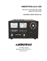
Wiring Pin Out and Relay Jack (Rear View)
Pin 1 – BCD A
Pin 2 – BCD B
Pin 3 – BCD C
NOTE: Ground is connected to the outer shell of the 8-pin din plug. Failure to connect
ground to the outer shell will result in the relay box not operating correctly.
Using the RCS-12 with other brand relay boxes
The RCS-12 was designed to be compatible with most off the shelf relay boxes. The RCS-12 Control
Head will work with any relay boxes using 3-line BCD, 4-line BCD, or 1 of 8 output; and require 12 – 30
VDC to switch the relays. The output format of the RCS-12 (BCD or 1 of 8) is changed by configuring
J9, J10, and J11 on the PCB (see diagram below to configure the RCS-12). Position the jumper on the
desired block to select the correct output needed for the relay box.
To connect the antenna switch to the relay box, the connections must be wired according to the output
chosen. The following diagram shows the connections to the relay jack for each mode of output. Ground
is provided using the outer shell of the plug.
4

Ameritron RCS-12 Instruction Manual Automatic Antenna Switch
3-line BCD 4-line BCD 1 of 8 Relay Connection Jack
Pin 1 – BCD A
Pin 2 – BCD B
Pin 3 – BCD C
Pin 1 – BCD A
Pin 2 – BCD B
Pin 3 – BCD C
Pin 4 – BCD D
Pin 1 – Antenna 1
Pin 2 – Antenna 2
Pin 3 – Antenna 3
Pin 4 – Antenna 4
Pin 5 – Antenna 5
Pin 6 – Antenna 6
Pin 7 – Antenna 7
Pin 8 – Antenna 8
(Rear View)
Selecting Direct or Regulated Relay Voltage
The RCS-12 provides two types of voltages for controlling the relays: Direct or Regulated. The default
setting is Direct and uses the power supplied to the RCS-12 to drive the switching relays. The Regulated
setting drives the relays using a 12V regulated supply. Selecting the correct modes is accomplished
setting JMP 4 located towards the front of the RCS-12.
Relay Power (JMP 4)
Direct Setting (Default) Regulated Setting
5
WARNING: NEVER APPLY MORE THAN +30 VDC TO THE RCS-12 POWER
JACK. The RCS-12 is compatible with relay boxes using up to 30 VDC.
Interfacing RCS-12 to Radio for Keying and Band Data
The RCS-12 is compatible with most Icom, Kenwood, and Yaesu radios for reading band data
information and detecting transmitter keying. The Radio Input connection is a DB-9 female jack that has
specific connections of each radio brand. The diagram below shows the pin-out of the Radio Input jack.
See the specific section below for more information on interfacing to each particular radio brand.
Radio Input Port Radio Input Pin-Out
(Rear View)
Pin 1 – Yaesu BCD B
Pin 2 – Yaesu BCD A
Pin 3 – Kenwood RX
Pin 4 – Kenwood TX
Pin 5 – Icom Band Data
Pin 6 – Ground
Pin 7 – Radio Key In
Pin 8 – Yaesu BCD D
Pin 9 – Yaesu BCD C
NOTE: Multiple radios cannot be connected to the RCS-12 at the same time. The RCS-12 is
designed to operate with only single radio.

Ameritron RCS-12 Instruction Manual Automatic Antenna Switch
Interfacing to Icom Radios
In order to retrieve band data from Icom radios, the RCS-12 must be connected to the band data voltage
output. This can be found on the ACC jack on the back of the radio. This 13-pin jack has the band data
voltage, amp key out (goes to ground when the radio is transmitting), and ground. The diagram below
shows the connections required between an Icom radio and the RCS-12.
Band Data Voltage
Ground
Amp Key/HSEND
RCS-12 Radio Input (Rear View)
ACC Socket (Rear View)
Icom Interface to RCS-12
Connection RCS-12 Radio Input Icom ACC Socket
Band Data Voltage Pin 5 Pin 5
Amp Key Pin 7 Pin 3
Ground Pin 6 Pin 2
6

Ameritron RCS-12 Instruction Manual Automatic Antenna Switch
Interfacing to Yaesu Radios
Yaesu radios output band information using a 4-line BCD format. The band data lines can be found on the
Linear port on most Yaesu radios. Some radios share the CAT port with the Linear port. The radio must
be configured so that the port is in Linear mode or the band data information will not be sent to the RCS-
12. Check your radio’s manual to determine proper configuration of the Linear port. The diagram below
shows the connection to the RCS-12. Double check with your radio’s manual to ensure the correct
connections for the Band Data.
G
r
o
u
n
d
Band Data A / BCD A
Band Data B / BCD B
Band Data C / BCD C
Band Data D / BCD D
TX GND / Amp Key
Linear Port (Rear View) RCS-12 Radio Input (Rear View)
Yaesu Interface to RCS-12
Interfacing to Kenwood Radios
The Computer port (CAT) is used to retrieve the frequency of the radio. When the RCS-12 is first turned
on, the “Auto Information” (AI) command is sent to the radio. This command causes the Kenwood radio
to output the state of the radio (frequency, mode, etc) anytime the state has changes. The RCS-12 then
uses the frequency to determine the appropriate band and then selects the correct antenna. The diagram
below shows how to connect a Kenwood radio with a DB-9 Com port to the RCS-12. Note that pin 7 and
8 (RTS, CTS) on the Kenwood port are connected together. This ensures that the Kenwood will send the
status information to the RCS-12. The Remote port is also found on the back of the Kenwood which has
the amp key line needed for the RCS-12. There is one second delay from when the status of the radio
changes until it is sent out over the serial connection.
Kenwood Interface to RCS-12
7
Note About Kenwood Radios
Since the Radio Control Port is used to get the band information from the radio. The radio must be
switched on first before powering up the RCS-12. Upon power up, the RCS-12 sends the Auto Information
(AI) command to the Kenwood radio. This instructs the Kenwood to send the radio’s status information
anytime it changes. Failure to do this will result in the radio not receiving this command and the RCS-12
not detecting a properly connected radio.
Anytime the status of the radio changes, there is a one second delay before the new information is sent
over the serial line to the RCS-12. This causes the switch to appear to respond slowly to the band changes.
This is a result of the delay from the Kenwood radio, NOT the RCS-12.

Ameritron RCS-12 Instruction Manual Automatic Antenna Switch
Auxiliary Input
The Auxiliary Input Port allows remote control of the antenna buttons on the antenna switch. The port is a
female DB-9 connection with the pin-out shown below. Applying a ground to any of the Aux pins will
select the appropriate antenna. Each pin is a +5Vdc with a 10K ohm resistor series circuit. When pulled
low, it will deliver .5 ma.
Auxiliary Input Port Auxiliary Input Pin-Out
Pin 1 – Antenna 1
Pin 2 – Antenna 2
Pin 3 – Antenna 3
Pin 4 – Antenna 4
Pin 5 – Antenna 5
Pin 6 – Antenna 6
Pin 7 – Antenna 7
Pin 8 – Antenna 8
Pin 9 - Ground
Auxiliary Output
The Auxiliary Output Port has two functions depending on the setting of JMP3. The output can be either
band data in 1 of 8 format or the current antenna selection. The default setting is band data.
Band Data Antenna Out (1 of 8)
On the Band Data setting , the output is the transceiver’s band in 1 of 8 format for HF. UHF/VHF bands
uses two pins. Pin 9 is also a TX line that goes to ground when the transmitter is keyed. This band data
can be used to control another device that can accept data in 1 of 8 format. The diagram below shows the
pin-out for each HF band.
Auxiliary Output Auxiliary Output (Band Data Setting)
Pin 1 – 160m
Pin 2 – 80m
Pin 3 – 40m
Pin 4 – 30m
Pin 5 – 20m
Pin 6 – 17m
Pin 7 – 15m
Pin 8 – 12m/10m
Pin 9 – TX Key
*Ground is on the shell of the DB-9 plug
8

Ameritron RCS-12 Instruction Manual Automatic Antenna Switch
When the transceiver or antenna is selected for a particular band. The pin on the Auxiliary Output jack
will corresponding to the band will be 5V. When using UHF/VHF the output from the Auxiliary Output
port will be as follows:
Band Pins
6m 1 & 8
Sub 2m 1 & 7
2m 1 & 6
70cm 1 & 5
33cm 1 & 4
23cm 1 & 3
NOTE: Some radios output the same band data for two bands such as the Icom (15m& 17m,
12m & 10m). Even though the radio has changed bands, it may not be reflected in the
band data output of the radio.
When the Auxiliary Output Port has been configured for Antenna Out. The output will correspond to the
currently selected antenna. Pin 9 is a TX line that goes to ground when the transmitter is keyed. The
diagram below shows the pin-out of the jack. The currently selected antenna’s pin on the Auxiliary Out
will be +5V while the remaining pins will be 0V.
Auxiliary Output Auxiliary Output (Antenna Out 1 of 8)
Pin 1 – Antenna 1
Pin 2 – Antenna 2
Pin 3 – Antenna 3
Pin 4 – Antenna 4
Pin 5 – Antenna 5
Pin 6 – Antenna 6
Pin 7 – Antenna 7
Pin 8 – Antenna 8
Pin 9 – TX Key
*Ground is on the shell of the DB-9 plug
Radio Key In
The Radio Key In jack, when pulled to ground, will prevent the RCS-12 from switching antennas. The
Radio Key In jack is +5V open collector and will deliver 1mA when pulled to ground. This jack should
be connected to the transceiver’s relay control line that goes to ground on transmit. This line is normally
used for keying an amplifier.
The Radio Key In jack and Pin 7 of the Radio Input Port are the same connection. Use only one of the
two connections.
Amp Key Out
The Amp Key Out jack will go to ground when the Radio Key In line is pulled to ground. This jack is
used for keying an amplifier’s T/R relay control line. This line can accept up to 25VDC at 1A.
The Amp Key Out jack and Pin 9 of the Aux Output Port is the same connection.
9

Ameritron RCS-12 Instruction Manual Automatic Antenna Switch
Operation
Manual Mode
Manual mode is achieved when the MODE switch, on the front panel of the RCS-12, is in the out
position. In this mode the RCS-12 will operate with simple push-button operation. Connection of the
RCS-12 to your Amplifier Key Line will protect your station against “hot switching”. Manual mode also
provides the function of letting a new antenna be selected while transmitting. The new antenna will be
switched after the transmitter is unkeyed, with a 10 ms delay to make sure a linear amplifier has time to
switch off. Do not attempt to use this function unless the Amplifier Key Line is connected to the Radio
Key In on the rear panel of the RCS-12, or else you will invoke severe damage to your station equipment
due to “hot switching.” Make sure the TRANSMIT LED on the front panel of the RCS-12 is always
illuminated when transmitting.
WARNING: Severe damage to your station equipment could happen if the Amp Key Line of your
transceiver is not connected to the RADIO KEY IN jack on the rear panel of the RCS-12 – due to
“hot switching.” See pages 6 & 7 for transceiver connections.
Automatic Mode
Automatic mode is achieved with the MODE switch in the in position. This mode will allow automatic
selection to a user programmable antenna . Only one antenna for each band may be selected. Automatic
antenna selection is accomplished by reading band data from the accessory port of your transceiver.
Saving Antenna Selections
In order to save an antenna selection, the radio must be connected to the RCS-12 and powered up. Set the
radio to the band you wish to set the antenna for. If an antenna has not been saved for a particular band,
the RCS-12 will sequentially light each antenna LED. Press and hold the desired antenna button for
approximately 2 seconds. The antenna’s LED will light, the antenna will be selected, and saved to
memory.
Multiple antennas can be saved for the same band. Saving other antennas is as simple as pressing and
holding the antenna to be selected. If there is more than one antenna saved for a particular band the LEDs
for the antennas saved, but not selected will flash. The RCS-12 will save all selected antennas for each
band plus the last active antenna that was used on that band.
After programming all the selections for the band information that the radio can output, the RCS-12 will
automatically select the correct antenna for each band. No other action is required by the user.
Erasing Antenna Selections
To erase an antenna selection simply select the band on the radio. Press the selected antenna button for
approximately 2 seconds. The antenna LED will extinguish and the antenna LEDs will being to light
sequentially.
10

Ameritron RCS-12 Instruction Manual Automatic Antenna Switch
Setting Relay Switching Delay
With the power switch off, hold the ANT 1 button while switching the RCS-12 power on. This allows the
setting of the relay switching delay. The delay is selected by pressing one of the eight antenna selection
buttons. The delays associated with each button are shown below. The default setting is 50ms (ANT 3).
ANT 1 ANT 2 ANT 3 ANT 4 ANT 5 ANT 6 ANT 7 ANT 8
1 ms 25ms 50ms 100ms 250ms 500ms 750ms 1s
The currently selected delay will have its associated LED lit and the remaining LEDs will be flashing.
Press the antenna button corresponding to the new delay desired. The selected antenna LED will light and
all the LEDs will flash confirming and saving your selection. The RCS-12 will then continue with normal
operation.
Resetting the RCS-12
Resetting the RCS-12 will clear out any saved settings and set the factory defaults. All saved settings will
be LOST!! To reset the RCS-12, switch the power off. While holding ANT 8, power up the RCS-12. All
the antenna LEDs will light for approximately 5 seconds. They will then flash confirming the unit has
been reset.
Troubleshooting
Problem Solution
All LEDs are flashing on
front panel.
RCS-12 is in automatic mode with no radio connected
Check connection from RCS-12 to radio.
Multiple radios have been connected to the RCS-12.
Only one radio can be connected at a time. Remove all but one of the
radios.
LEDs are flashing
sequentially rapidly.
There is not a saved antenna for the current band. Save an antenna for the
band.
RCS-12 with Kenwood radio
changes antennas slowly.
There is a one second delay from when the status of the radio changes
until the information is serially sent out to the switch. Because of this, the
RCS-12 will not see a band change until the information has been sent by
the radio. This causes the RCS-12 to change antennas slower with the
Kenwood radios.
Remote Relay box not
selecting or selecting
incorrect antennas.
Ensure the Output Select (J9, J10, and J11) is set for the correct output for
the relay box. Check to ensure the wiring is connected to the relay box in
the correct order.
Transmit LED not lit during
radio transmission
Ensure the Amp Key from the radio is connected to the Radio Key In on
the back of the RCS-12 on the Radio Input Jack (Pin 7) or the RCA Jack.
11

Ameritron RCS-12 Instruction Manual Automatic Antenna Switch
Technical Assistance
If you have any problem with this unit first check the appropriate section of this manual. If the manual
does not reference your problem or your problem is not solved by reading the manual, you may call
Ameritron at 662-323-8211. You will be best helped if you have your unit, manual and all information on
your station handy so you can answer any questions the technicians may ask.
You can also send questions by mail to Ameritron, 116 Willow Road, Starkville, MS 39759; by facsimile
(FAX) to 662-323-6551. Send a complete description of your problem, an explanation of exactly how
you are using your unit, and a complete description of your station.
12


42
DISCLAIMER
Information in this manual is designed for user purposes only and is not intended to
supersede information contained in customer regulations, technical manuals/documents,
positional handbooks, or other official publications. The copy of this manual provided to
the customer will not be updated to reflect current data.
Customers using this manual should report errors or omissions, recommendations for
improvements, or other comments to Ameritron 116 Willow Road, Starkville, MS 39759.
Phone: (662) 323-8211; FAX: (662) 323-6551. Business hours: M-F 8-4:30 CST.
AMERITRON
116 Willow Road
Starkville, MS 39759 USA
662-323-8211
LIMITED WARRANTY
Ameritron warrants to the original purchaser that this product shall be free from defects in material or workmanship for
one year from the date of original purchase. During the warranty period, Ameritron (or an authorized Ameritron
service facility) will provide free of charge both parts and labor necessary to correct defects in material or
workmanship.
To obtain such warranty service, the original purchaser must:
(1) Complete and send in the Warranty Registration Card.
(2) Notify Ameritron or its nearest authorized service facility, as soon as possible after discovery of a possible
defect, of:
(a) the model number and serial number, if any:
(b) the identity of the seller and the approximate date ofpurchase;
(c) a detailed description of the problem, including details on the equipment.
(3) Deliver the product to the Ameritron or the nearest authorized service facility, or ship the same in its original
container or equivalent, fully insured and with shipping charges prepaid.
Correct maintenance, repair, and use are important to obtain proper performance from this product. Therefore, carefully
read the Instruction Manual. This warranty does not apply to any defect that Ameritron determines is due to:
(1) Improper maintenance or repair, including the installation of parts or accessories that do not conform to the quality
and specifications of the original parts.
(2) Misuse, abuse, neglect or improper installation.
(3) Accidental or intentional damage.
All implied warranties, if any, terminate one (1) year from the date of the original purchase.
The foregoing constitutes Ameritron's entire obligation with respect to this product, and the original purchaser and any
user or owner shall have no remedy and no claim for incidental or consequential damages. Some states do not allow
limitations on how long an implied warranty lasts or do not allow the exclusion or limitation of incidental or
consequential damage, so the above limitation and exclusion may not apply to you.
This warranty gives specific legal rights and you may also have other rights, which vary from state to state.
/