Page is loading ...

ARB-704 Interface Buffer Instruction Manual
1
Ameritron ARB-704
IMPORTANT !
1.) This manual is for advanced users, who want to wire their own
cables. Detailed information in this manual describes input
requirements and output limitations of this device.
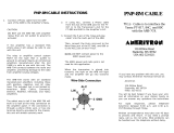
2.) Ameritron also offers prewired plug-and-play cables. If you use
prewired plug-and-play cables, you can ignore this manual
and use the simple instructions that are included in the plug-
and-play cable assembly for your radio.
3.) Many radios do not require a plug-and-play cable assembly,
and can use basic cables included with the ARB-704. These
radios are listed on the plug-and-play sheet included with this
unit.
INTRODUCTION
The ARB-704 advanced interface is compatible with all common radios and
amplifiers even though radios and amplifiers do not have standardized voltages,
accessory plugs, or wiring. This interface is designed to work with any
amplifier/radio combination. The input is designed to be compatible with any
transmitter or transceiver, and the output is compatible with AC control lines or
DC positive or negative amplifier control lines having up to 200 volts peak open
circuit voltage and 300mA of operating current.
Ameritron offers several plug-and-play cables that interface more common
radios to the ARB-704. Plug-and-play cables for various radios as well as radios
not requiring a special cable assembly are listed on a loose page enclosed in this
manual.
WHY YOU NEED THE ARB-704
Amplifiers can damage radios if the amplifier has too much relay control
voltage, voltage spikes, or excessive current on the relay control line. Such
damage often appears as “stuck” or “sticky” transmit relays in exciters or shorted

ARB-704 Interface Buffer Instruction Manual
2
transistors on transmit control lines. In most cases where the radio is damaged,
the system transmits normally but the external amplifier stays locked in a
“transmit” mode. This prevents receive signals from coming through the
amplifier with normal levels whenever the amplifier is in the “ON” or
“OPERATE” position.
One protection or buffering system requires installation of a low-current
isolation relay between the radio and amplifier. Unfortunately an isolation
relay’s field coil can still draw appreciable current, and relay coils produce a
voltage spike when unkeyed. If a back-pulse canceling diode is installed to
suppress back EMF or coil back-pulse voltage, relay release time increases.
Most amplifiers are already marginal on pull-in time. Even if current, release
time, and back-pulse aren’t excessive, closure time is always noticeably
increased because of the pull-in time delay of mechanical isolation relays. If the
external “isolation relay” adds enough pull-in delay, the radio’s output signal can
appear before the amplifier’s internal relay completely transfers the antenna to
the amplifier output. This is called “hot switching”, and it can cause serious
damage to the amplifier and radio.
Hot switching can destroy an expensive bandswitch or tuning capacitor in the
amplifier, as well as cause annoying “clicks” or “pops” outside of your operating
frequency. Besides being rough on equipment and annoying to people operating
close to your frequency, hot-switching can also mutilate your sending. On CW,
the entire first “dot” might disappear…making a call like AA4MM sound like
TA4MM.
The ARB-704 has many electrical advantages over conventional relay buffer
systems. The ARB-704, since it has no moving parts, switches almost
instantaneously. The ARB-704 is noiseless, has very long life, and will not
develop dirty contacts. It operates with negative, AC, or positive amplifier relay
control lines.
The ARB-704 works with any relay voltage (AC, positive, or negative) up to 200
peak volts and any relay current up to 300mA. The ARB-704 is fully compatible
with conventional amplifier relay systems. It is especially suited for buffering
vacuum relay QSK amplifiers, since the ARB-704 does not affect attack or
release times in a deleterious manner.
The ARB-704 operates with transmitters or transceivers that pull amplifier
control lines to ground, or output a wide range of positive or negative control

ARB-704 Interface Buffer Instruction Manual
3
voltages. The transmitter only switches currents under 0.35 milliamperes and
very low voltages when using the ARB-704.
WARNING:
1.) Never use this unit with relay coils operated directly from power
lines (such as old amplifiers with external 120 VAC line
powered relays). AC coil relays can be switched if operated
from a small isolation transformer.
2.) This unit is NOT ground isolated. It electrically connects the
amplifier relay closure terminal to chassis when activated.
3.) Equipment damage and shock hazards will be present if you
fail to properly connect ground leads to the amplifier and/or
radio. Always be sure to connect the additional safety ground
lead to the station ground buss from the ARB-704. Always be
sure the amplifier ground return and radio ground return leads
are connected.
TECHNICAL DESCRIPTION
The ARB-704 uses four transistors and one operational amplifier. It has a red
LED indicator that illuminates when the relay control line is activated. The
ARB-704 accepts either traditional low = transmit (TX-SEND) or less common
high=transmit (TX-SEND) amplifier control outputs from the radio.
The ARB-704 RADIO input current and voltage requirements are minimal.
Only a few volts and much less than one milliampere is required for normal
operation. Virtually any radio can directly operate the ARB-704.
The ARB-704’s unique output circuit pulls either positive or negative amplifier
relay control lines to ground. Nearly any amplifier relay system is compatible
with the ARB-704. The ARB-704 can safely handle open circuit voltages up to
200 volts DC or peak AC, and carry relay currents up to 300mA.

ARB-704 Interface Buffer Instruction Manual
4
CONNECTIONS
Connect the amplifier control line (often called TX-SEND line) of your radio to
the RADIO jack or to pin 3 of the ARB-704 MULTI-PORT jack.
JMP1 and JMP2, located inside the ARB-704, must be positioned to match the
type of output from the TX-SEND radio control line. The following control
voltage jumper settings are available:
RADIO (TX-SEND) = Low systems 2.5 volt threshold (most common system
used) 5 volts open circuit
This system activates whenever the RADIO (TX-SEND) line pulls below
approximately 2 volts. Only 100µA of current appears at the output terminal
when pulled low, and open circuit voltage is ~5 volts. This line is diode
blocked, so the radio can pull up to any voltage above ~5 volts without any
current being drawn from the radio. A pull-down resistance of less than 15k-
ohms activates the system.
RADIO (TX-SEND) = Low systems 2.1 volt threshold (IC-706 series) 2.5 or
more volts open circuit.

ARB-704 Interface Buffer Instruction Manual
5
This system activates whenever the RADIO line pulls below 2.1 volts. Only
100µA of current appears at the output terminal when pulled low, and open
circuit voltage is 2.5 volts. This line is diode blocked, so the radio can pull up to
any voltage above 2.5 volts without any current being drawn from the radio send
line. A pull down resistance of less than 100k-ohms activates the system.
This system is suitable for rigs like the IC-706, where the “send” line is shared
with other radio functions and cannot be loaded.
RADIO (TX-SEND) = Negative systems
This system activates whenever the RADIO line goes more than 1 volt negative.
Less than 350µA of current is consumed when pulled negative to 5 volts, and
open circuit voltage is 2.5 volts positive.
RADIO (TX-SEND) = Positive systems
This system activates whenever the RADIO line is pulled above 3 volts. Only
50µA of current appears at the output terminal when pulled low, and open circuit
voltage is 2.5 volts. This system consumes 1/2mA of current with 12 volts
applied.

ARB-704 Interface Buffer Instruction Manual
6
Note: Most modern transceivers have TX-SEND lines that switch low
(to ground) when transmitting. They use settings of JMP1
and JMP2 for conventional TX-low keying.
Exceptions are transmitters that have very sensitive keying
systems (like the IC-706), transmitters that output positive
voltage when sending (unusual for most radios), and radios
having a negative send voltage (some older radios).
The AMP jack (J1) is a standard phono (commonly called “RCA”) jack. When
this unit is properly connected, this jack will pull relay lines with 100 mA of
current (typical for most amplifiers) within 0.7 volts of ground. This jack is
capable of handling 200 volts of maximum open-circuit voltage. The voltage
can be positive, AC or negative. Maximum rated current is 300mA.
The ALC jack is normally connected when using plug-and play cables, and
when amplifier ALC is used. It connects to the amplifier’s ALC output. In other
cases where amplifier ALC is used, the ALC output from the amplifier can be
connected directly to the radio with a standard shielded phono (RCA) connector
cable (such as cables used for home stereo and VCR audio lines).
INSTALLATION
The ARB-704 requires external voltage to operate. This voltage can be obtained
from any filtered 9-18 volt dc supply capable of supplying up to 50 mA.
Some radios have suitable operating voltage available on the same radio
connector used for control line and ALC connections. In such cases, power is
obtained from the radio’s accessory or control jack through plug-and-play cables
and no other connections are required. In other cases, power can be obtained
either from the 12-volt station power supply or through a separate wall adaptor
(also called a “wall-wart”). Ameritron offers a 12-volt wall adaptor, Model:
MFJ-1315.
WARNING:

ARB-704 Interface Buffer Instruction Manual
7
Never
connect the power jack to a voltage source capable of
supplying more than one ampere without proper fuses. Use a ½
ampere fast-blow fuse to protect the wiring and your power supply
from accidental short circuits.
When unplugged
, the standard 12-volt plug used with this unit can
accidentally come in contact with other devices that may be
damaged by excessive current. Always disconnect the power
source end of the power cable first, or turn the power supply off,
before removing or inserting the power connector into the ARB-
704. Never insert or remove the power plug from the ARB-704 while
power is on.
Never
use power from the radio and power from an external
adaptor at the same time.
Always
be sure the red lead is positive, and the black lead is
grounded. Reversing the leads may damage the ARB-704, the
radio, or the power supply.
RELAY control:
Virtually all transmitters or transceivers have an internal relay that can be used to
ground the amplifier's control line. The radio’s manual will show a set of
contacts in a simple diagram, or have the jack labeled NO (normally open), NC
(normally closed), and COM (common). At other times transmitter control
connections are labeled: Transmit, T or TX, Receive R or RX, and C or
common.
In modern transceivers, the NC (normally closed) contact is often omitted. The
NC contact was commonly used to control muting (standby) of external
receivers, such as old tube-type equipment like Drake Twins or Collins 32/75
series.
TRANSISTOR control:
Some transceivers use a transistor for external amplifier control. The transistor
normally pulls to ground (low) on transmit.
VOLTAGE control:
A few radios use voltage to switch external amplifiers. The IC-706 is a current
example of this. In the IC-706, voltage on a very low current control pin drops

ARB-704 Interface Buffer Instruction Manual
8
low when transmitting. This line cannot be loaded with more than a few mA of
current draw, nor can external circuits try to force this line higher than a few
volts. If these precautions are not heeded, the radio will not work properly or
may be damaged. The ARB-704 is designed to function perfectly with the IC-
706.
WIRING
Many radios and most amplifiers have standard RCA phono jacks for TX SEND
connections. When radios have phono plugs, connections can be made using
common home stereo or VCR system audio cables. It is NOT necessary to run
the ALC line through the ARB-704. The ARB-704 only provides a straight-
through ALC connection for convenience when using Ameritron’s plug-and-play
radio cables.
To wire or connect your own cables, use the radio manual’s section on external
power amplifiers or accessory connections that describe transceiver or radio
connections to external power amplifiers. The drawing will typically show a
relay contact connection described as N.O., SEND, or TX (transmit) for external
amplifier control. On some radios you may have to set a switch inside the radio.
The FT1000D is one radio that requires changing an internal switch to activate
the external relay. The radio’s manual, in the section describing use of external
power amplifiers, will tell you if changing a switch is necessary.
The NO or TX-SEND connection on the radio wires to the center pin of the
RADIO female phono (RCA) lead of the ARB-704, or to pin 3 of the ARB-704
DIN connector.
If the transceiver or transmitter has an internal relay with a contact marked COM
or C, connect this pin to the shell of the ARB-704 RADIO phono jack or to pin
2 of the ARB-704 DIN connector. If your radio’s amplifier control line uses an
RCA phono jack, the ground connection will be made through the shell of the
jack. No addition ground connection is necessary if you use a standard shielded
audio cable for the connection to the RADIO jack on the ARB-704.
QSK Radios
Some QSK transceivers (mostly early Yaesu’s) have a control terminal or jack
labeled “Inhibit” or “Linear” that has to be grounded on transmit. Consult the
radio manual for details on this particular requirement. This connection prevents
hot switching of an external power amplifier, and is normally wired to a “hand-
shake” line on a QSK amplifier that tells the radio the amplifier has successfully
gone in the transmit mode.

ARB-704 Interface Buffer Instruction Manual
9
If a radio having this connection is not being used with a QSK amplifier, or is
being used with a QSK amplifier without a “hand-shake” or “TX enabled”
output, the radio inhibit control line must be connected to the radio’s chassis
ground. If the amplifier has a “TX enabled” line, or when using an Ameritron
QSK-5, connect a jumper cable from the radio “Inhibit” or “Linear” input to the
Handshake or “TX Ready” line on the amplifier or amplifier QSK switch.
ALC
Many radios have ALC inputs. If you want to use the ALC output of an
amplifier, connect the radio ALC input directly to the amplifier’s ALC output. If
you use a plug and play cable connect the amplifier ALC to the ALC phono jack
on the ARB-704.
AMP RELAY
WARNING: Do not exceed 200 volts peak voltage or 300 mA
current on the ARB-704’s AMP jack. This jack is ground
referenced, but will handle AC, positive, or negative
amplifier relay voltages.
The Amplifier relay connection is through the AMP phono plug on the ARB-
704.
POWER
A red-black wire pair with matching plug is included with this unit for use with
external power supplies. The red wire is positive, and the black wire is negative.
The voltage must be between 9 and 18 volts DC. Be sure to properly fuse the
red lead with a ½ ampere fast-blow fuse when using high current supplies
(capable of over 2 amperes).
1.) Connect the red lead (positive center pin) of the power cord assembly to the
proper positive DC supply voltage. This voltage must be 9-18 volts
positive.
2.) Connect the black (negative outer sleeve) lead to the negative of the power
supply. It is normally not necessary to fuse this lead, as long as the negative
terminal of the station power supply is properly grounded.

ARB-704 Interface Buffer Instruction Manual
10
Note
:
Transceivers or transmitters have several methods of
controlling external amplifiers. You can usually find this
information in the radio manual section dealing with
“External Amplifiers”, “External Control”, “Accessories”, or
“Rear Panel Connections”.
WARNING: Do not use the power cord and jack when using power
through the rear panel DIN plug!
TECHNICAL ASSISTANCE
If you have any problem with this unit first check the appropriate section of this
manual. If the manual does not reference your problem or reading the manual
does not solve your problem, call Ameritron at 662-323-8211. We can only help
if you have your ARB-704 manual, radio manual, and information about your
station available during the call.
We strongly recommend calling Ameritron with any questions, but questions
can be mailed directly to Ameritron at 116 Willow Road, Starkville, MS 39759
or Faxed to 662-323-9810. Please be aware that MFJ is a separate facility, and
as such does not always offer the best assistance with Ameritron products. Be
sure to send a complete description of the problem, explain how this unit is being
used, and include a complete description of your station.

ARB-704 Interface Buffer Instruction Manual
11
SCHEMATIC
/
