Page is loading ...

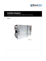
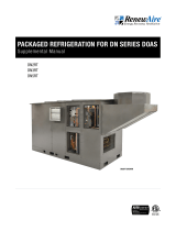
Model DN3RT Shown
DN2RT
DN3RT
DN5RT
DN SERIES DOAS
Installation, Operation and Maintenance Manual

1.800.627.44992
DN-Series Rooftop
DOAS
RISK OF ELECTRIC SHOCK OR EQUIPMENT DAMAGE
Whenever electrical wiring is connected, disconnected or
changed, the power supply to the DOAS and its controls must
be disconnected. Lock and tag the disconnect switch or circuit
breaker to prevent accidental reconnection of electric power.
RISK OF CONTACT WITH HIGH SPEED MOVING PARTS.
Disconnect all local and remote power supplies, verify with
a voltmeter that electric power is off and all fan blades have
stopped rotating before working on the unit.
Do not operate this unit with any cabinet panels removed.
RISK OF DAMAGE TO ENTHALPIC CORES
Whenever working within the DOAS cabinet, protect the enthal-
pic cores from accidental damage. The core media is subject to
damage from dropped tools or other foreign objects.
Low air flow can cause fouling of the enthalpic cores. The
DOAS must never be operated without clean filters in place and
minimum airflow must be greater than 250 CFM per full-
sized core.
RISK OF CONTACT WITH HOT SURFACES
The blower motor and other electrical components are
extremely hot during operation. Allow sufficient time for them
to cool before working within the unit cabinet. Use extreme
caution and wear protective gloves and arm protection when
working on or near hot blower motors and
electrical components.
FIRE OR EXPLOSION HAZARD
This unit may include a gas heater.
Read and comply with all safety information and warnings in
the RenewAire Indirect Gas-Fired Heater User Manual that is
included with the unit.
ARC FLASH AND ELECTRIC SHOCK HAZARD
Arc flash and electric shock hazard. Disconnect all electric
power supplies, verify with a voltmeter that electric power
is off and wear protective equipment per NFPA 70E before
working within electric control enclosure. Failure to comply can
cause serious injury or death.
Customer must provide earth ground to unit, per NEC, CEC and
local codes, as applicable.
Before proceeding with installation, read all instructions, veri-
fying that all the parts are included and check the nameplate to
be sure the voltage matches available utility power.
The line side of the disconnect switch contains live
high-voltage.
The only way to ensure that there is NO voltage inside the unit
is to install and open a remote disconnect switch and verify
that power is off with a volt meter. Refer to unit
electrical schematic.
Follow all local codes.
WARNING WARNING
CAUTION
CAUTION
CAUTION
RISK OF ELECTRIC SHOCK
Optional VFDs use capacitors that will retain a high voltage
charge even after power is disconnected. After fans come to
a complete stop, wait for five minutes for the capacitors to
discharge themselves.
CAUTION
CAUTION
This unit is intended for general ventilating only. Do not use
to exhaust hazardous or explosive materials and vapors. Do
not connect this equipment to range hoods, fume hoods or
collection systems for toxics.
IMPORTANT
Do not release refrigerant into the atmosphere! If
required service procedures include the adding or removal
of refrigerant, the service technician must comply with all
federal, state and local laws. The procedures discussed in
this manual should only be performed by a qualified, EPA
Certified technician.
IMPORTANT
IMPORTANT
This equipment is to be installed by following Industry Best
Practices and all applicable codes. Any damage to
components, assemblies, subassemblies or the cabinet
which is caused by improper installation practices will void
the warranty.
This unit is for ventilating finished structures only. It is not
to be used until after all construction has been completed
and construction debris and dust are cleaned from the
Occupied Space.
IMPORTANT

31.800.627.4499
DN-Series Rooftop DOAS
READ AND SAVE THIS MANUAL/LIRE ET CONSERVER CE MANUEL
UNIT INFORMATION
UNIT LABEL (TYPICAL)
UNIT INFORMATION
NOTICE
This manual contains space for maintaining written records of unit maintenance and/or
repairs. See Section 7.2 Maintenance Records. At the time the DOAS is commissioned, a
maintenance schedule should be developed by the user to incorporate monthly and seasonal
maintenance and include start-up maintenance tasks as described in this manual.
In the unlikely event that factory assistance is ever required, information located on the unit
label will be needed.
D-- R - -N J - -T
Record information as shown below.
Locate the RenewAire unit label found on the outside of the unit.
NOTE: This information is for purposes of identifying the unit-specific option data from the
Option Code.
OPTION CODE:
SERIAL NUMBER:
SO #:
OWNER INFORMATION
NOTE: This page
is to be completed
by the installing
contractor. The completed
document is to be turned
over to the owner after
start-up.

1.800.627.44994
Subject to change without notice: RENEWAIRE.COM | 1.800.627.4499 98 Subject to change without notice: RENEWAIRE.COM | 1.800.627.4499
SPECIFICATIONS & DIMENSIONS
2RTDN
Dedicated Outdoor Air System
Standard
SPECIFICATIONS
Energy Recovery Type:
Static plate total energy transfer
Typical Airflow Range: 375-1,650 CFM
AHRI 1060 Certified Core:
One L-62-G5 and one L-125-G5
ETL Certification:
Tested to UL standards 1812 and 1995
Standard Features:
EC Motors for both airstreams
Direct Drive backward inclined plenum
Higher ESP of up to 2" w.g. at 1,500 CFM
Integrated programmable controls
True 100% Face and bypass enthalpy based
modulating economizer
Class 1 low leakage motorized isolation dampers
Stainless steel double-sloped drain pan with
cooling option
1", 20 gauge galvanized double wall foam-injected
R6.5 insulation
Modbus RTU or IP Integration
Inlets/Outlets:
OA & RA Inlets: 24" x 16"
SA Outlet: 24" x 16"
EA Outlet: 20" x 16"
Filters:
Total qty. 4, MERV 8:
16" x 20" x 2"
Unit Weight for 1" Cabinets: 1500-2700 lbs.
Max. Shipping Dimensions & Weight for 1"
Cabinets (on pallet):
140" L x 90" W x 79" H
1700-2900 lbs.
Unit Weight for 2" Cabinets: 1600-2825 lbs.
Max. Shipping Dimensions & Weight for 2"
Cabinets (on pallet):
140" L x 90" W x 81" H
1800-3025 lbs.
Motor(s):
Qty. 2, Direct drive motorized impeller packages
Options:
DX, heat pump, or chilled water cooling coil
Modulating hot gas reheat
Steam or hot water coil, gas heat module or
electric heater
Onboard variable frequency drives (VFDs) -
both airstreams
Fused disconnect
Spring isolators (VFDs only)
2", 20 gauge galvanized double wall foam-injected
R13 insulation with thermal break construction
Exterior paint - grey, white, custom color
Salt spray - 2500 hour
BACNET factory activation
GFCI convenience outlet
Recirculation damper
Drain overflow switch
Mist eliminator
Electrofin coating for coils
Accessories:
Filters - MERV 13, 2" and 4" (shipped loose),
MERV 14, 2" and 4" (shipped loose)
Additional filters available upon request
Roof curb - standard 14"
Custom hurricane or seismic rated curbs
Curb clip kit
Carbon dioxide sensor/control -
wall mount (CO2-W), duct mount (CO2-D)
IAQ sensor - wall mount (IAQ-W),
duct mount (IAQ-D)
Motion occupancy sensor/control -
ceiling mount (MC-C), wall mount (MC-W)
Smoke detector
Room temperature and humidity sensor
Duct static pressure sensor with display to 10",
without display 0-2"
Room pressure sensor with display to 1",
without display 0-1"
Waterless trap negative pressure
Waterless trap positive pressure
Remote display
ROOFTOP UNIT
Dedicated Outside Air System
Unit with Energy Recovery
ERV - Energy Recovery Ventilator
EH - Electric Heater
CC - Cooling Coil
HC - Heating Coil
GH - Gas Heat Module
HGRH - Hot Gas Reheat Coil
BT - Blow Thru
DT - Draw Thru
INTERNAL OPTIONS FOR HEATING AND COOLING
ERV only ERV + EH (BT) ERV + GH (BT) ERV + CC/HC (BT) ERV + CC + HGRH (BT) ERV + CC/HC (DT) ERV + CC + HGRH (DT)
ERV + CC + HGRH + EH (BT)ERV + CC + EH (BT) ERV + CC + GH (BT) ERV + CC + HGRH + GH (BT) ERV + CC + HC (BT) ERV + CC + HGRH + HC (BT)
ERV + CC + EH (DT) ERV + CC + HGRH + EH (DT) ERV + CC + GH (DT) ERV + CC + HGRH + GH (DT) ERV + CC + HC (DT) ERV + CC + HGRH + HC (DT)
DN3IN, ERV + CC + HGRH + GH (BT) shown
Energy Recovery Core is AHRI Certified
®

51.800.627.4499
Subject to change without notice: RENEWAIRE.COM | 1.800.627.4499 98 Subject to change without notice: RENEWAIRE.COM | 1.800.627.4499
SPECIFICATIONS & DIMENSIONS
2RTDN Dedicated Outdoor Air System
Standard
Electrical Specifications
Motor Qty/kW
or HP Volts Frequency Phase Min. Cir.
Amps.
Max.
Overcurrent
Protection
Device
FLA
per motor
EC
2 @ 1.35 kW ea. 200-277 50/60 Hz Single 15.1 20 6.7-4.8
2 @ 2.70 kW ea. 200-240 50/60 Hz Three 19.4 25 8.6-7.2
2 @ 3.70 kW ea. 380-480 50/60 Hz Three 13.5 15 6.0-4.6
VFD
2 @ 3HP ea. 208-230 50/60 Hz Three 20.3 25 9-8.4/4.2
2 @ 3HP ea. 460 50/60 Hz Three 9.5 15 4.2
2 @ 3HP ea. 575 50/60 Hz Three 7.4 15 3.3
Note: Electrical data shown is for a standard unit without cooling and heating. Refer to cores.renewaire.com for project
specific submittal for electrical data for the specific unit with all included options.
ELECTRICAL DATA
AIRFLOW PERFORMANCE
0.0
0.5
1.0
1.5
2.0
2.5
3.0
3.5
4.0
4.5
5.0
5.5
6.0
250 500 750 1000 1250 1500 1750 2000
External Static Pressure (in.w.g.)
Air Flow (cfm)
DN-2 200-277V 1P EC
0.0
0.5
1.0
1.5
2.0
2.5
3.0
3.5
4.0
4.5
5.0
5.5
6.0
250 500 750 1000 1250 1500 1750 2000
External Static Pressure (in.w.g.)
Air Flow (cfm)
DN-2 200-240V 3P EC
0.0
0.5
1.0
1.5
2.0
2.5
3.0
3.5
4.0
4.5
5.0
5.5
6.0
250 500 750 1000 1250 1500 1750 2000
External Static Pressure (in.w.g.)
Air Flow (cfm)
DN-2 230/460/575V 3P AC
0.0
0.5
1.0
1.5
2.0
2.5
3.0
3.5
4.0
4.5
5.0
5.5
6.0
250 500 750 1000 1250 1500 1750 2000
External Static Pressure (in.w.g.)
Air Flow (cfm)
DN-2 380-480V 3P EC

1.800.627.44996
Subject to change without notice: RENEWAIRE.COM | 1.800.627.4499 1110 Subject to change without notice: RENEWAIRE.COM | 1.800.627.4499
SPECIFICATIONS & DIMENSIONSSPECIFICATIONS & DIMENSIONS
123 7/8" Roof
151 5/8" Overall
8 7/8"
FRONT VIEW
SA
OA
RA
1" NPT
Condensate Drain
(opt)
RA
SA
(opt)
Disconnect Switch
and EBOX
Gas Heat Connections
Locations Vary
12 1/8"
13 7/8"
48"
Case
RIGHT VIEW
RA Duct Flange
24" x 16"
16 7/8"
18 5/8"
LEFT VIEW
EA
(2) 7/8" Holes
for Power and Controls
Field Wiring
SA Duct Flange
24" x 16"
Gas Heat
Combustion
Air Intake
Gas Heat
Combustion
Exhaust
73 1/8"
Overall
119 7/8" Case
BACK VIEW
Coil Connections
Locations Vary
52 1/8"
Roof
76 3/4"
Overall
119 7/8" Minimum
Service Area
40" Minimum
Service Area
26 1/8"
16"
32 5/8"
16"
36" Minimum
Service Area
74" Minimum
Service Area
TOP VIEW
RA (Floor; Optional)
24" x 16"
Door
Swing
SA (Floor; Optional)
24" x 16"
Model: DN-2JRT ERV+COIL+HEAT 1"
Drawing Type: Unit Dimension
Version: AUG19
ABBREVIATIONS
EA: Exhaust Air to outside
OA: Outside Air intake
RA: Room Air to be exhausted
SA: Supply Air to inside
INSTALLATION ORIENTATION
Unit must be installed in orientation
shown.
NOTE
1. UNLESS OTHERWISE SPECIFIED,
DIMENSIONS ARE ROUNDED TO THE
NEAREST EIGHTH OF AN INCH.
2. SPECIFICATIONS MAY BE SUBJECT
TO CHANGE WITHOUT NOTICE.
3. FOR PIPE CONNECTION DETAILS
REFER TO CORES OR UNIT SELECTION
SUBMITTAL.
4. UNIT, UNIT DOORS, AND COILS
CANNOT BE MIRRORED.
5. FOR CURB DETAILS REFER TO CURB
DRAWING.
6. FOR PROJECT SPECIFIC DRAWINGS
REFER TO PROJECT SUBMITTAL.
Coil Options: DX, CW, HGRH
Heat Options: HW, Electric, Gas, Steam
DN2RT
Dedicated Outdoor Air System Standard 1" Cabinet
UNIT MOUNTING & APPLICATION
Must be mounted as shown. Airstreams can not be
switched.
AIRFLOW ORIENTATION
Available as shown:
Dimension drawings for the DN depict largest cabinet size available.
Refer to CORES.RenewAire.com for project specific unit drawings.
AO
RA
AE
BACK
SA
DNRT
H
AE
BACK
SA
AO
RA
DNIN
F
AR
SA
AO
AE
BACK
DNRT
V
AE
BACK
AR
AO
SA
DNRT
R
NOTE: This drawing represents the DN-2-RT with 1"
thick wall panels, coils and heat module. Dimensioned
drawings for other configurations are found on the
RenewAire website.

71.800.627.4499
Subject to change without notice: RENEWAIRE.COM | 1.800.627.4499 1110 Subject to change without notice: RENEWAIRE.COM | 1.800.627.4499
SPECIFICATIONS & DIMENSIONS
DN2RT
Dedicated Outdoor Air System Standard 2" Cabinet
9 7/8"
154 1/8" Overall
125 7/8" Roof
FRONT VIEW
SA
OA
RA
1" NPT
Condensate Drain
(opt)
RA
SA
(opt)
Disconnect Switch
and EBOX
Gas Heat Connections
Locations Vary
50"
Case
13"
14 7/8"
RIGHT VIEW
RA Duct Flange
24" x 16"
19 5/8"
17 7/8"
LEFT VIEW
EA
(2) 7/8" Holes
for Power and Controls
Field Wiring
SA Duct Flange
24" x 16"
Gas Heat
Combustion
Air Intake
Gas Heat
Combustion
Exhaust
121 7/8" Case
75 1/8"
Overall
BACK VIEW
Coil Connections
Locations Vary
78 5/8"
Overall 54 1/8"
Roof
119 7/8" Minimum
Service Area
40" Minimum
Service Area
36" Minimum
Service Area
74" Minimum
Service Area
33 1/8"
17"
27"
16 3/4"
TOP VIEW
RA (Floor; Optional)
24" x 16"
Door
Swing
SA (Floor; Optional)
24" x 16"
Model: DN-2JRT ERV+COIL+HEAT 2"
Drawing Type: Unit Dimension
Version: NOV18
ABBREVIATIONS
EA: Exhaust Air to outside
OA: Outside Air intake
RA: Room Air to be exhausted
SA: Supply Air to inside
INSTALLATION ORIENTATION
Unit must be installed in orientation
shown.
NOTE
1. UNLESS OTHERWISE SPECIFIED,
DIMENSIONS ARE ROUNDED TO THE
NEAREST EIGHTH OF AN INCH.
2. SPECIFICATIONS MAY BE SUBJECT
TO CHANGE WITHOUT NOTICE.
3. FOR PIPE CONNECTION DETAILS
REFER TO CORES OR UNIT SELECTION
SUBMITTAL.
4. UNIT, UNIT DOORS, AND COILS
CANNOT BE MIRRORED.
5. FOR CURB DETAILS REFER TO CURB
DRAWING.
6. FOR PROJECT SPECIFIC DRAWINGS
REFER TO PROJECT SUBMITTAL.
Coil Options: DX, CW, HGRH
Heat Options: HW, Electric, Gas, Steam
UNIT MOUNTING & APPLICATION
Must be mounted as shown. Airstreams can not be
switched.
AIRFLOW ORIENTATION
Available as shown:
Dimension drawings for the DN depict largest cabinet size available.
Refer to CORES.RenewAire.com for project specific unit drawings.
AO
RA
AE
BACK
SA
DNRT
H
AE
BACK
SA
AO
RA
DNIN
F
AR
SA
AO
AE
BACK
DNRT
V
AE
BACK
AR
AO
SA
DNRT
R
NOTE: This drawing represents the DN-2-RT with 2"
thick wall panels, coils and heat module. Dimensioned
drawings for other configurations are found on the
RenewAire website.

1.800.627.44998
Subject to change without notice: RENEWAIRE.COM | 1.800.627.4499 1312 Subject to change without notice: RENEWAIRE.COM | 1.800.627.4499
SPECIFICATIONS & DIMENSIONSSPECIFICATIONS & DIMENSIONS
DN2RT
Dedicated Outdoor Air System Curbs
UNIT MOUNTING & APPLICATION
This universal DN Series curb can be used in
conjunction with RTF, RTH, RTV and RTR models.
AIRFLOW ORIENTATION
Available as shown:
8 1/2"
26 7/8"
25 3/4" 59 1/8" 25 3/4"
28 1/4"
1 7/8"
110 5/8" I.D.
35 3/8" I.D.
5 1/4"
39 1/8" O.D.
20" 20"
114 3/8" O.D.
1 1/2"
TYP.
AA
1 7/8"
3"
14"
SECTION A-A
1 1/2" x 1/4"
Neoprene Gasket
1 1/2" x 3 1/2"
Wooden Nailer
14"
TOP VIEW
DN2RT
CURB DN2-ERV+C+H
DUCT SUPPORT DIMENSIONS
WIDTH: 1 1/2" DEPTH: 3"
FRONT VIEW
RA
SA
END VIEW
CURB CROSS-SECTION A-A (TYP.)
Model: CURB DN2 ERV+C+H
Drawing Type: Curb Dimension
Version: OCT 18
RA: Room Air to be exhausted
SA: Supply Air to inside
Dimension drawings for the DN depict largest cabinet size available.
Refer to CORES.RenewAire.com for project specific unit drawings.
THIS PAGE IS INTENTIONALLY LEFT BLANK.
AO
RA
AE
BACK
SA
DNRT
H
AE
BACK
SA
AO
RA
DNIN
F
AR
SA
AO
AE
BACK
DNRT
V
AE
BACK
AR
AO
SA
DNRT
R
NOTE: This drawing represents the DN-2-RT with coils and heat
module. Dimensioned drawings for other configurations are
found on the RenewAire website.

91.800.627.4499
DN-Series Rooftop DOAS
THIS PAGE IS INTENTIONALLY LEFT BLANK.

1.800.627.449910
Subject to change without notice: RENEWAIRE.COM | 1.800.627.4499 2524 Subject to change without notice: RENEWAIRE.COM | 1.800.627.4499
SPECIFICATIONS & DIMENSIONS
3RTDN Dedicated Outdoor Air System
Standard
SPECIFICATIONS
Energy Recovery Type:
Static plate total energy transfer
Typical Airflow Range: 750-3,300 CFM
AHRI 1060 Certified Core:
Three L-125-G5
ETL Certification:
Tested to UL standards 1812 and 1995
Standard Features:
EC Motors for both airstreams
Direct Drive backward inclined plenum
Higher ESP of up to 2.5" w.g. at 3,000 CFM
Integrated programmable controls
True 100% Face and bypass enthalpy based
modulating economizer
Class 1 low leakage motorized isolation dampers
Stainless steel double-sloped drain pan with
cooling option
1", 20 gauge galvanized double wall foam-injected
R6.5 insulation
Modbus RTU or IP Integration
Inlets/Outlets:
OA & RA Inlets: 36" x 16"
SA Outlet: 24" x 16"
EA Outlet: 20" x 16"
Filters:
Total qty. 6, MERV 8:
20" x 20" x 2"
Unit Weight for 1" Cabinets: 2000-3950 lbs.
Max. Shipping Dimensions & Weight for 1"
Cabinets (on pallet):
160" L x 90" W x 81" H
2225-4175 lbs.
Unit Weight for 2" Cabinets: 2125-4150 lbs.
Max. Shipping Dimensions & Weight for 2"
Cabinets (on pallet):
160" L x 90" W x 83" H
2350-4375 lbs.
Motor(s):
Qty. 2, Direct drive motorized impeller packages
Options:
DX, heat pump, or chilled water cooling coil
Modulating hot gas reheat
Steam or hot water coil, gas heat module or
electric heater
Onboard variable frequency drives (VFDs) -
both airstreams
Fused disconnect
Spring isolators (VFDs only)
2", 20 gauge galvanized double wall foam-injected
R13 insulation with thermal break construction
Exterior paint - grey, white, custom color
Salt spray - 2500 hour
BACNET factory activation
GFCI convenience outlet
Recirculation damper
Drain overflow switch
Mist eliminator
Electrofin coating for coils
Accessories:
Filters - MERV 13, 2" and 4" (shipped loose),
MERV 14, 2" and 4" (shipped loose)
Additional filters available upon request
Roof curb - standard 14"
Custom hurricane or seismic rated curbs
Curb clip kit
Carbon dioxide sensor/control -
wall mount (CO2-W), duct mount (CO2-D)
IAQ sensor - wall mount (IAQ-W),
duct mount (IAQ-D)
Motion occupancy sensor/control -
ceiling mount (MC-C), wall mount (MC-W)
Smoke detector
Room temperature and humidity sensor
Duct static pressure sensor with display to 10",
without display 0-2"
Room pressure sensor with display to 1",
without display 0-1"
Waterless trap negative pressure
Waterless trap positive pressure
Remote display
ROOFTOP UNIT
Dedicated Outside Air System
Unit with Energy Recovery
ERV - Energy Recovery Ventilator
EH - Electric Heater
CC - Cooling Coil
HC - Heating Coil
GH - Gas Heat Module
HGRH - Hot Gas Reheat Coil
BT - Blow Thru
DT - Draw Thru
INTERNAL OPTIONS FOR HEATING AND COOLING
ERV only ERV + EH (BT) ERV + GH (BT) ERV + CC/HC (BT) ERV + CC + HGRH (BT) ERV + CC/HC (DT) ERV + CC + HGRH (DT)
ERV + CC + HGRH + EH (BT)ERV + CC + EH (BT) ERV + CC + GH (BT) ERV + CC + HGRH + GH (BT) ERV + CC + HC (BT) ERV + CC + HGRH + HC (BT)
ERV + CC + EH (DT) ERV + CC + HGRH + EH (DT) ERV + CC + GH (DT) ERV + CC + HGRH + GH (DT) ERV + CC + HC (DT) ERV + CC + HGRH + HC (DT)
DN3IN, ERV + CC + HGRH + GH (BT) shown
Energy Recovery Core is AHRI Certified
®

111.800.627.4499
Subject to change without notice: RENEWAIRE.COM | 1.800.627.4499 2524 Subject to change without notice: RENEWAIRE.COM | 1.800.627.4499
SPECIFICATIONS & DIMENSIONS
3RTDN Dedicated Outdoor Air System
Standard
ELECTRICAL DATA
Electrical Specifications
Motor Qty/kW
or HP Volts Frequency Phase Min. Cir.
Amps.
Max.
Overcurrent
Protection
Device
FLA
per motor
EC 2 @ 2.70 kW ea. 200-240 50/60 Hz Three 19.4 25 8.6-7.2
2 @ 3.70 kW ea. 380-480 50/60 Hz Three 13.5 15 6.0-4.6
VFD
2 @ 5HP ea. 208-230 50/60 Hz Three 31.3 45 13.9-13.4/6.7
2 @ 5HP ea. 460 50/60 Hz Three 15.1 20 6.7
2 @ 5HP ea. 575 50/60 Hz Three 11.9 15 5.3
Note: Electrical data shown is for a standard unit without cooling and heating. Refer to cores.renewaire.com for project
specific submittal for electrical data for the specific unit with all included options.
AIRFLOW PERFORMANCE
0.0
0.5
1.0
1.5
2.0
2.5
3.0
3.5
4.0
4.5
5.0
5.5
6.0
750 1000 1250 1500 1750 2000 2250 2500 2750 3000 3250 3500
External Static Pressure (in.w.g.)
Air Flow (cfm)
DN-3 200-240V 3P EC
0.0
0.5
1.0
1.5
2.0
2.5
3.0
3.5
4.0
4.5
5.0
5.5
6.0
750 1000 1250 1500 1750 2000 2250 2500 2750 3000 3250 3500
External Static Pressure (in.w.g.)
Air Flow (cfm)
DN-3 230/460/575V 3P AC
0.0
0.5
1.0
1.5
2.0
2.5
3.0
3.5
4.0
4.5
5.0
5.5
6.0
750 1000 1250 1500 1750 2000 2250 2500 2750 3000 3250 3500
External Static Pressure (in.w.g.)
Air Flow (cfm)
DN-3 380-480V 3P EC

1.800.627.449912
Subject to change without notice: RENEWAIRE.COM | 1.800.627.4499 2726 Subject to change without notice: RENEWAIRE.COM | 1.800.627.4499
SPECIFICATIONS & DIMENSIONSSPECIFICATIONS & DIMENSIONS
DN3RT Dedicated Outdoor Air System Standard 1" Cabinet
145 5/8" Roof
174 7/8" Overall
8 7/8"
FRONT VIEW
SA
OA
RA
1" NPT
Condensate Drain
(opt)
RA
SA
(opt)
Disconnect Switch
and EBOX
Gas Connections
Locations Vary
13 7/8"
20 3/4"
77 3/8"
Case
RIGHT VIEW
RA Duct Flange
36" x 16"
26 3/4"
16 7/8"
LEFT VIEW
EA
(2) 7/8" Holes
for Power and Controls
Field Wiring
SA Duct Flange
24" x 16"
Gas Heat
Combustion
Air Intake
Gas Heat
Combustion
Exhaust
141 3/4" Case
75 1/8"
Overall
BACK VIEW
Coil Connections
Locations Vary
106 1/8"
Overall
141 3/4" Minimum
Service Area
75" Minimum
Service Area
81 1/2"
Roof
36" Minimum
Service Area
96" Minimum
Service Area
40"
Door Swing
40 7/8" 40 7/8"
15 7/8"
16 1/8"
TOP VIEW
SA (Floor; Optional)
24" x 16"
RA (Floor; Optional)
36" x 16"
Model: DN-3JRT ERV+COIL+HEAT 1"
Drawing Type: Unit Dimension
Version: NOV18
ABBREVIATIONS
EA: Exhaust Air to outside
OA: Outside Air intake
RA: Room Air to be exhausted
SA: Supply Air to inside
INSTALLATION ORIENTATION
Unit must be installed in orientation
shown.
NOTE
1. UNLESS OTHERWISE SPECIFIED,
DIMENSIONS ARE ROUNDED TO THE
NEAREST EIGHTH OF AN INCH.
2. SPECIFICATIONS MAY BE SUBJECT
TO CHANGE WITHOUT NOTICE.
3. FOR PIPE CONNECTION DETAILS
REFER TO CORES OR UNIT SELECTION
SUBMITTAL.
4. UNIT, UNIT DOORS, AND COILS
CANNOT BE MIRRORED.
5. FOR CURB DETAILS REFER TO CURB
DRAWING.
6.FOR PROJECT SPECIFIC DRAWINGS
REFER TO PROJECT SUBMITTAL.
Coil Options: DX, CW, HGRH
Heat Options: HW, Electric, Gas, Steam
AIRFLOW ORIENTATION
Available as shown:
Dimension drawings for the DN depict largest cabinet size available.
Refer to CORES.RenewAire.com for project specific unit drawings.
UNIT MOUNTING & APPLICATION
Must be mounted as shown. Airstreams can not be
switched.
AO
RA
AE
BACK
SA
DNRT
H
AE
BACK
SA
AO
RA
DNIN
F
AR
SA
AO
AE
BACK
DNRT
V
AE
BACK
AR
AO
SA
DNRT
R
NOTE: This drawing represents the DN-3-RT with 1" thick wall
panels, coils and heat module. Dimensioned drawings for other
configurations are found on the RenewAire website.

131.800.627.4499
Subject to change without notice: RENEWAIRE.COM | 1.800.627.4499 2726 Subject to change without notice: RENEWAIRE.COM | 1.800.627.4499
SPECIFICATIONS & DIMENSIONS
DN3RT
Dedicated Outdoor Air System Standard 2" Cabinet
176 7/8" Overall
9 7/8"
147 5/8" Roof
FRONT VIEW
SA
OA
RA
1" NPT
Condensate Drain
(opt)
RA
SA
(opt)
Disconnect Switch
and EBOX
Gas Connections
Locations Vary
79 3/8"
Case
21 3/4"
14 7/8"
RIGHT VIEW
RA Duct Flange
36" x 16"
27 3/4"
18 1/8"
LEFT VIEW
EA
(2) 7/8" Holes
for Power and Controls
Field Wiring
SA Duct Flange
24" x 16"
Gas Heat
Combustion
Air Intake
Gas Heat
Combustion
Exhaust
77 1/8"
Overall
143 3/4" Case
BACK VIEW
Coil Connections
Locations Vary
108 3/4"
Overall 83 1/2"
Roof
143 3/4" Minimum
Service Area
75" Minimum
Service Area
36" Minimum
Service Area
96" Minimum
Service Area
40"
Door Swing
41 7/8"
41 7/8"
17 1/8"
17"
RA (Floor; Optional)
36" x 16"
SA (Floor; Optional)
24" x 16"
TOP VIEW
Model: DN-3JRT ERV+COIL+HEAT 2"
Drawing Type: Unit Dimension
Version: NOV18
ABBREVIATIONS
EA: Exhaust Air to outside
OA: Outside Air intake
RA: Room Air to be exhausted
SA: Supply Air to inside
INSTALLATION ORIENTATION
Unit must be installed in orientation
shown.
NOTE
1. UNLESS OTHERWISE SPECIFIED,
DIMENSIONS ARE ROUNDED TO THE
NEAREST EIGHTH OF AN INCH.
2. SPECIFICATIONS MAY BE SUBJECT
TO CHANGE WITHOUT NOTICE.
3. FOR PIPE CONNECTION DETAILS
REFER TO CORES OR UNIT SELECTION
SUBMITTAL.
4. UNIT, UNIT DOORS, AND COILS
CANNOT BE MIRRORED.
5. FOR CURB DETAILS REFER TO CURB
DRAWING.
6. FOR PROJECT SPECIFIC DRAWINGS
REFER TO PROJECT SUBMITTAL.
Coil Options: DX, CW, HGRH
Heat Options: HW, Electric, Gas, Steam
UNIT MOUNTING & APPLICATION
Must be mounted as shown. Airstreams can not be
switched.
AIRFLOW ORIENTATION
Available as shown:
Dimension drawings for the DN depict largest cabinet size available.
Refer to CORES.RenewAire.com for project specific unit drawings.
AO
RA
AE
BACK
SA
DNRT
H
AE
BACK
SA
AO
RA
DNIN
F
AR
SA
AO
AE
BACK
DNRT
V
AE
BACK
AR
AO
SA
DNRT
R
NOTE: This drawing represents the DN-3-RT
with 2" thick wall panels, coils and heat module.
Dimensioned drawings for other configurations
are found on the RenewAire website.

1.800.627.449914
Subject to change without notice: RENEWAIRE.COM | 1.800.627.4499 2928 Subject to change without notice: RENEWAIRE.COM | 1.800.627.4499
SPECIFICATIONS & DIMENSIONSSPECIFICATIONS & DIMENSIONS
DN3RT Dedicated Outdoor Air System Curbs
UNIT MOUNTING & APPLICATION
This universal DN Series curb can be used in
conjunction with RTF, RTH, RTV and RTR models.
AIRFLOW ORIENTATION
Available as shown:
16 5/8"
31 1/8" 70 1/8" 31 1/8"
40 1/4"
10 5/8"
132 3/8" I.D.
61 3/8" I.D.
10 5/8"
28 1/4"
16 5/8"
1 1/2"
TYP.
65 1/8" O.D.
20" 20"
136 1/8" O.D.
AA
1 7/8"
3"
14"
SECTION A-A
1 1/2" x 1/4"
Neoprene Gasket
1 1/2" x 3 1/2"
Wooden Nailer
14"
TOP VIEW
DN3RT
CURB DN3-ERV+C+H
DUCT SUPPORT DIMENSIONS
WIDTH: 1 1/2" DEPTH: 3"
FRONT VIEW
RA
SA
END VIEW
CURB CROSS-SECTION A-A (TYP.)
Model: CURB DN3 ERV+C+H
Drawing Type: Curb Dimension
Version: OCT 18
RA: Room Air to be exhausted
SA: Supply Air to inside
Dimension drawings for the DN depict largest cabinet size available.
Refer to CORES.RenewAire.com for project specific unit drawings.
THIS PAGE IS INTENTIONALLY LEFT BLANK.
AO
RA
AE
BACK
SA
DNRT
H
AE
BACK
SA
AO
RA
DNIN
F
AR
SA
AO
AE
BACK
DNRT
V
AE
BACK
AR
AO
SA
DNRT
R
NOTE: This drawing represents the DN-3-RT with coils and heat
module. Dimensioned drawings for other configurations are
found on the RenewAire website.

151.800.627.4499
DN-Series Rooftop DOAS
THIS PAGE IS INTENTIONALLY LEFT BLANK.

1.800.627.449916
Subject to change without notice: RENEWAIRE.COM | 1.800.627.4499 4140 Subject to change without notice: RENEWAIRE.COM | 1.800.627.4499
SPECIFICATIONS & DIMENSIONS
5RTDN Dedicated Outdoor Air System
Standard
SPECIFICATIONS
Energy Recovery Type:
Static plate total energy transfer
Typical Airflow Range: 1,125-4,950 CFM
AHRI 1060 Certified Core:
One L-62-G5 and four L-125-G5
ETL Certification:
Tested to UL standards 1812 and 1995
Standard Features:
EC Motors for both airstreams
Direct Drive backward inclined plenum
Higher ESP of up to 3" w.g. at 4,500 CFM
Integrated programmable controls
True 100% Face and bypass enthalpy based
modulating economizer
Class 1 low leakage motorized isolation dampers
Stainless steel double-sloped drain pan with
cooling option
1", 20 gauge galvanized double wall foam-injected
R6.5 insulation
Modbus RTU or IP Integration
Inlets/Outlets:
OA & RA Inlets: 60" x 16"
SA Outlet: 24" x 16"
EA Outlet: 20" x 32"
Filters:
Total qty. 10, MERV 8:
16" x 20" x 2"
Bypass Filters:
Total qty. 4, MERV 8:
16" x 20" x 2"
Unit Weight for 1" Cabinets: 2975-5500 lbs.
Max. Shipping Dimensions & Weight for 1"
Cabinets (on pallet):
180" L x 101 1/2" W x 98" H
3225-5750 lbs.
Unit Weight for 2" Cabinets: 3100-5700 lbs.
Max. Shipping Dimensions & Weight for 2"
Cabinets (on pallet):
180" L x 101 1/2" W x 100" H
3350-5950 lbs.
Motor(s):
Qty. 4, Direct drive motorized impeller packages
Options:
DX, heat pump, or chilled water cooling coil
Modulating hot gas reheat
Steam or hot water coil, gas heat module or
electric heater
Onboard variable frequency drives (VFDs) -
both airstreams
Fused disconnect
Spring isolators (VFDs only)
2", 20 gauge galvanized double wall foam-injected
R13 insulation with thermal break construction
Exterior paint - grey, white, custom color
Salt spray - 2500 hour
BACNET factory activation
GFCI convenience outlet
Recirculation damper
Drain overflow switch
Mist eliminator
Electrofin coating for coils
Accessories:
Filters - MERV 13, 2" and 4" (shipped loose),
MERV 14, 2" and 4" (shipped loose)
Additional filters available upon request
Roof curb - standard 14"
Custom hurricane or seismic rated curbs
Curb clip kit
Carbon dioxide sensor/control -
wall mount (CO2-W), duct mount (CO2-D)
IAQ sensor - wall mount (IAQ-W),
duct mount (IAQ-D)
Motion occupancy sensor/control -
ceiling mount (MC-C), wall mount (MC-W)
Smoke detector
Room temperature and humidity sensor
Duct static pressure sensor with display to 10",
without display 0-2"
Room pressure sensor with display to 1",
without display 0-1"
Waterless trap negative pressure
Waterless trap positive pressure
Remote display
ROOFTOP UNIT
Dedicated Outside Air System
Unit with Energy Recovery
ERV - Energy Recovery Ventilator
EH - Electric Heater
CC - Cooling Coil
HC - Heating Coil
GH - Gas Heat Module
HGRH - Hot Gas Reheat Coil
BT - Blow Thru
DT - Draw Thru
INTERNAL OPTIONS FOR HEATING AND COOLING
ERV only ERV + EH (BT) ERV + GH (BT) ERV + CC/HC (BT) ERV + CC + HGRH (BT) ERV + CC/HC (DT) ERV + CC + HGRH (DT)
ERV + CC + HGRH + EH (BT)ERV + CC + EH (BT) ERV + CC + GH (BT) ERV + CC + HGRH + GH (BT) ERV + CC + HC (BT) ERV + CC + HGRH + HC (BT)
ERV + CC + EH (DT) ERV + CC + HGRH + EH (DT) ERV + CC + GH (DT) ERV + CC + HGRH + GH (DT) ERV + CC + HC (DT) ERV + CC + HGRH + HC (DT)
DN3IN, ERV + CC + HGRH + GH (BT) shown
Energy Recovery Core is AHRI Certified®

171.800.627.4499
Subject to change without notice: RENEWAIRE.COM | 1.800.627.4499 4140 Subject to change without notice: RENEWAIRE.COM | 1.800.627.4499
SPECIFICATIONS & DIMENSIONS
5RTDN Dedicated Outdoor Air System
Standard
ELECTRICAL DATA
Electrical Specifications
Motor Qty/kW
or HP Volts Frequency Phase Min. Cir.
Amps.
Max.
Overcurrent
Protection
Device
FLA
per motor
EC 4 @ 2.70 kW ea. 200-240 50/60 Hz Three 36.6 45 8.6-7.2
4 @ 3.70 kW ea. 380-480 50/60 Hz Three 25.5 30 6.0-4.6
VFD
4 @ 5HP ea. 208-230 50/60 Hz Three 59.1 70 13.9-13.4/6.7
4 @ 5HP ea. 460 50/60 Hz Three 28.5 35 6.7
4 @ 5HP ea. 575 50/60 Hz Three 22.5 25 5.3
Note: Electrical data shown is for a standard unit without cooling and heating. Refer to cores.renewaire.com for project
specific submittal for electrical data for the specific unit with all included options.
AIRFLOW PERFORMANCE
0.0
0.5
1.0
1.5
2.0
2.5
3.0
3.5
4.0
4.5
5.0
5.5
6.0
1000 1500 2000 2500 3000 3500 4000 4500 5000 5500 6000
External Static Pressure (in.w.g.)
Air Flow (cfm)
DN-5 200-240V 3P EC
0.0
0.5
1.0
1.5
2.0
2.5
3.0
3.5
4.0
4.5
5.0
5.5
6.0
1000 1500 2000 2500 3000 3500 4000 4500 5000 5500 6000
External Static Pressure (in.w.g.)
Air Flow (cfm)
DN-5 230/460/575V 3P AC
0.0
0.5
1.0
1.5
2.0
2.5
3.0
3.5
4.0
4.5
5.0
5.5
6.0
1000 1500 2000 2500 3000 3500 4000 4500 5000 5500 6000
External Static Pressure (in.w.g.)
Air Flow (cfm)
DN-5 380-480V 3P EC

1.800.627.449918
Subject to change without notice: RENEWAIRE.COM | 1.800.627.4499 4342 Subject to change without notice: RENEWAIRE.COM | 1.800.627.4499
SPECIFICATIONS & DIMENSIONSSPECIFICATIONS & DIMENSIONS
DN5RT
Dedicated Outdoor Air System Standard 1" Cabinet
8 7/8"
172" Roof
205 1/8" Overall
FRONT VIEW
SA
OA
RA
1" NPT
Condensate Drain
(opt)
RA
SA
(opt)
Disconnect Switch
and EBOX
Gas Heat Connections
Locations Vary
15 1/2"
14"
91"Case
RIGHT VIEW
RA Duct Flange
60" x 16"
33 1/2"
17"
LEFT VIEW
EA
(2) 7/8" Holes
for Power and Controls
Field Wiring
SA Duct Flange
24" x 16"
Gas Heat
Combustion
Air Intake
Gas Heat
Combustion
Exhaust
92 1/8"
Overall
168" Case
BACK VIEW
Coil Connections
Locations Vary
95 1/8"
Roof
126 3/8"
Overall
168" Minimum
Service Area
80" Minimum
Service Area
47 1/2"
17"
40"
Door Swing
47 1/2"
16"
118" Minimum Service Area
36" Minimum Service Area
TOP VIEW
RA (Floor; Optional)
60" x 16"
SA (Floor; Optional)
24" x 16"
Model: DN-5JRT ERV+COIL+HEAT 1"
Drawing Type: Unit Dimension
Version: NOV18
ABBREVIATIONS
EA: Exhaust Air to outside
OA: Outside Air intake
RA: Room Air to be exhausted
SA: Supply Air to inside
INSTALLATION ORIENTATION
Unit must be installed in orientation
shown.
NOTE
1. UNLESS OTHERWISE SPECIFIED,
DIMENSIONS ARE ROUNDED TO THE
NEAREST EIGHTH OF AN INCH.
2. SPECIFICATIONS MAY BE SUBJECT
TO CHANGE WITHOUT NOTICE.
3. FOR PIPE CONNECTION DETAILS
REFER TO CORES OR UNIT SELECTION
SUBMITTAL.
4. UNIT, UNIT DOORS, AND COILS
CANNOT BE MIRRORED.
5. FOR CURB DETAILS REFER TO CURB
DRAWING.
6. FOR PROJECT SPECIFIC DRAWINGS
REFER TO PROJECT SUBMITTAL.
Coil Options: DX, CW, HGRH
Heat Options: HW, Electric, Gas, Steam
UNIT MOUNTING & APPLICATION
Must be mounted as shown. Airstreams can not be
switched.
AIRFLOW ORIENTATION
Available as shown:
Dimension drawings for the DN depict largest cabinet size available.
Refer to CORES.RenewAire.com for project specific unit drawings.
AO
RA
AE
BACK
SA
DNRT
H
AE
BACK
SA
AO
RA
DNIN
F
AR
SA
AO
AE
BACK
DNRT
V
AE
BACK
AR
AO
SA
DNRT
R
NOTE: This drawing represents the DN-5-RT with 1" thick wall panels, coils and heat
module. Dimensioned drawings for other configurations
are found on the RenewAire website.

191.800.627.4499
Subject to change without notice: RENEWAIRE.COM | 1.800.627.4499 4342 Subject to change without notice: RENEWAIRE.COM | 1.800.627.4499
SPECIFICATIONS & DIMENSIONS
DN5RT
Dedicated Outdoor Air System Standard 2" Cabinet
207 1/8" Overall
9 7/8"
174" Roof
FRONT VIEW
SA
OA
RA
1" NPT
Condensate Drain
(opt)
RA
SA
(opt)
Disconnect Switch
and EBOX
Gas Heat Connections
Locations Vary
16 1/2"
15 1/4"
93" Case
RIGHT VIEW
RA Duct Flange
60" x 16"
34 1/2"
18 1/4"
LEFT VIEW
EA
(2) 7/8" Holes
for Power and Controls
Field Wiring
SA Duct Flange
24" x 16"
Gas Heat
Combustion
Air Intake
Gas Heat
Combustion
Exhaust
170" Case
94 1/8"
Overall
BACK VIEW
Coil Connections
Locations Vary
128 3/8"
Overall
97 1/8"
Roof
168" Minimum
Service Area
80" Minimum
Service Area
48 5/8"
19"
40"
Door Swing
48 1/2"
15 1/8"
118" Minimum Service Area
36" Minimum Service Area
TOP VIEW
RA (Floor; Optional)
60" x 16"
SA (Floor; Optional)
24" x 16"
Model: DN-5JRT ERV+COIL+HEAT 2"
Drawing Type: Unit Dimension
Version: AUG18
ABBREVIATIONS
EA: Exhaust Air to outside
OA: Outside Air intake
RA: Room Air to be exhausted
SA: Supply Air to inside
INSTALLATION ORIENTATION
Unit must be installed in orientation
shown.
NOTE
1. UNLESS OTHERWISE SPECIFIED,
DIMENSIONS ARE ROUNDED TO THE
NEAREST EIGHTH OF AN INCH.
2. SPECIFICATIONS MAY BE SUBJECT
TO CHANGE WITHOUT NOTICE.
3. FOR PIPE CONNECTION DETAILS
REFER TO CORES OR UNIT SELECTION
SUBMITTAL.
4. UNIT, UNIT DOORS, AND COILS
CANNOT BE MIRRORED.
5. FOR CURB DETAILS REFER TO CURB
DRAWING.
6. FOR PROJECT SPECIFIC DRAWINGS
REFER TO PROJECT SUBMITTAL.
Coil Options: DX, CW, HGRH
Heat Options: HW, Electric, Gas, Steam
UNIT MOUNTING & APPLICATION
Must be mounted as shown. Airstreams can not be
switched.
AIRFLOW ORIENTATION
Available as shown:
Dimension drawings for the DN depict largest cabinet size available.
Refer to CORES.RenewAire.com for project specific unit drawings.
AO
RA
AE
BACK
SA
DNRT
H
AE
BACK
SA
AO
RA
DNIN
F
AR
SA
AO
AE
BACK
DNRT
V
AE
BACK
AR
AO
SA
DNRT
R
NOTE: This drawing represents the DN-5-RT with 2" thick wall panels, coils and
heat module. Dimensioned drawings for other
configurations are found on the RenewAire website.

1.800.627.449920
Subject to change without notice: RENEWAIRE.COM | 1.800.627.4499 4544 Subject to change without notice: RENEWAIRE.COM | 1.800.627.4499
SPECIFICATIONS & DIMENSIONSSPECIFICATIONS & DIMENSIONS
DN5RT
Dedicated Outdoor Air System Curbs
UNIT MOUNTING & APPLICATION
This universal DN Series curb can be used in
conjunction with RTF, RTH, RTV and RTR models.
AIRFLOW ORIENTATION
Available as shown:
23 3/8"
24 3/4" 24 3/4"
64 1/4"
5 3/8"
158 5/8" I.D.
75" I.D.
5 3/8"
1 1/2"
TYP.
28 1/4" 23 3/8"
78 3/4" O.D.
20" 20"
162 3/8" O.D.
27 7/8" 27 3/8" 27 7/8" 25 7/8"
AA
1 7/8"
3"
14"
SECTION A-A
1 1/2" x 1/4"
Neoprene Gasket
1 1/2" x 3 1/2"
Wooden Nailer
14"
TOP VIEW
DN5RT
CURB DN5-ERV+C+H
DUCT SUPPORT DIMENSIONS
WIDTH: 1 1/2" DEPTH: 3"
FRONT VIEW
RA
SA
END VIEW
CURB CROSS-SECTION A-A (TYP.)
Model: CURB DN5 ERV+C+H
Drawing Type: Curb Dimension
Version: OCT 18
RA: Room Air to be exhausted
SA: Supply Air to inside
Dimension drawings for the DN depict largest cabinet size available.
Refer to CORES.RenewAire.com for project specific unit drawings.
THIS PAGE IS INTENTIONALLY LEFT BLANK.
AO
RA
AE
BACK
SA
DNRT
H
AE
BACK
SA
AO
RA
DNIN
F
AR
SA
AO
AE
BACK
DNRT
V
AE
BACK
AR
AO
SA
DNRT
R
NOTE: This drawing represents the DN-5-RT coils and heat module. Dimensioned
drawings for other configurations are found on the RenewAire website.
/