Page is loading ...

This manual contains installation, operation, and maintenance
instructions. Read thoroughly before you begin installing. Failure
to follow these instructions may result in personal injury or death,
damage to the unit, or incorrect operation.
RTF
Rooftop Freezer Systems
Form 200.108-IOM (OCT 2022)
Installation – Operation – Maintenance
File: Service Manual – Section 200
Replaces: 200.108-IOM (FEB 2018)
Distribution: 3, 3a, 3b, 3c
Check www.FrickCold.com for the latest version of this publication.

200.108-IOM (OCT 2022)
Page 2
RTF Rooftop Freezer Systems
Installation - Operation - Maintenance
Indicates an imminently hazardous situation that, if not avoided, results in death or serious in-
jury.
Indicates a potentially hazardous situation or practice that, if not avoided, results in death or
serious injury.
Safety precaution denitions
Indicates a potentially hazardous situation or practice that, if not avoided, results in damage to
equipment and/or minor injury.
Indicates an operating procedure, practice, or portion thereof that is essential to highlight.
DANGER
WARNING
CAUTION
NOTICE
Contents
Read before proceeding .................................................... 3
Changeability of this document ........................................ 3
General information
Receiving the shipment .....................................................4
Inspecting the shipment ............................................... 4
Checking for a leak .......................................................4
Transit damage and shortage claim .............................. 4
Safety ................................................................................4
Warranty ........................................................................... 5
Pre-installation requirements ............................................5
Training and safety considerations .............................. 5
Preliminary site layout considerations .......................... 5
Preliminary eld piping design considerations ............. 5
Electrical power ............................................................6
Refrigeration ................................................................ 6
Condensate drain .........................................................6
Installation
Installation safety guidelines .............................................8
Electric ......................................................................... 8
Fans ..............................................................................8
Vibration and noise ......................................................8
Support structure information .......................................... 8
RTF supported by roof curb ..............................................9
Suggested roof to curb nish ............................................ 9
Roof curb ........................................................................10
Preparing the roof curb .............................................. 10
Rigging the roof curb..................................................10
Setting the roof curb ..................................................10
RTF unit .......................................................................... 11
Preparing the RTF unit ................................................ 11
Rigging and lifting the RTF unit .................................. 11
Setting the RTF unit ................................................... 12
Setting the RTF unit without a roof curb .................... 12
Installing the roof membrane ..................................... 13
Sealing the RTF enclosure .......................................... 15
Discharge air plenum ...................................................... 16
Preparation the discharge plenum ..............................16
Installing the discharge plenum .................................. 16
Electrical ......................................................................... 17
120 V service power ..................................................17
Refrigeration ................................................................... 19
Refrigerant piping .................................................. 19
Flooded surge vessels support ................................... 19
Evaporator condensate drain piping ........................... 19
Operation
Start-up ..........................................................................20
Before start-up ........................................................... 20
Maintenance
Unit exterior ...................................................................21
Coil maintenance ............................................................ 21

200.108-IOM (OCT 2022)
Page 3
RTF Rooftop Freezer Systems
Installation - Operation - Maintenance
Read before proceeding
Use the information in this manual to safely and correctly
install, operate, and maintain the Roof Top Freezer (RTF)
Systems Units.
Frick® strongly suggests that personnel become fully
familiar with this manual before operating or working on a
RTF unit.
After installing the unit, the relevant personnel must
correctly connect it to an appropriately designed and
installed refrigeration system. The engineering plans, pip-
ing layouts, and any other relevant design and installation
material must be detailed in accordance with local codes
and applicable industry standards and practices.
Rig and install units as outlined in this manual. Review
these procedures in detail before the actual rigging
operation to acquaint all personnel with the procedures.
If you have any questions or comments about this manual,
call your sales representative.
NOTICE
This manual, in combination with the applicable
cooling coil data, unit G&A drawing, unit electrical
drawing, roof curb drawing, and, discharge plenum
drawing, provides the information necessary to
safely install and start up a Frick RTF unit. Due to the
possibility of customization associated with the RTF
product line, there may be areas beyond the scope
of this manual. If there are any questions about a
special application lacking the required information,
contact the installing contractor or your local Frick
sales ofce.
Changeability of this document
In complying with Johnson Controls® policy for continu-
ous product improvement, the information contained in
this document is subject to change without notice. While
Frick makes no commitment to update or provide current
information automatically to the manual owner, that in-
formation, if applicable, can be obtained by contacting the
nearest Frick Factor or the nearest Frick Sales ofce.
It is the responsibility of operating or service personnel to
verify the applicability of these documents to the equip-
ment in question. If there is any question in the mind of
operating or service personnel as to the applicability of
these documents, then before working on the equipment,
they need to verify with the owner whether the equipment
has been modied and if current literature is available.
WARNING
External wiring is not to be connected inside an
RTF factory mounted electrical panel unless spe-
cically indicated as required eld wiring on the
Frick electrical drawings provided. Devices such as
relays, switches, transducers and controls may not
be installed inside the Frick RTF electrical panel.
No external wiring is allowed to be run through
the Frick RTF electrical panel. All wiring must be in
accordance with Frick published specications and
must be performed only by qualied Frick personnel.
Frick will not be responsible for damages/problems
resulting from improper connections to the controls
or application of improper control signals. Failure to
follow this will void the manufacturer’s warranty and
may cause serious damage to property or injury to
persons.

200.108-IOM (OCT 2022)
Page 4
RTF Rooftop Freezer Systems
Installation - Operation - Maintenance
General information
Receiving the shipment
Inspecting the shipment
Do not accept the delivery until you inspect the shipment
on arrival. This is to ensure that all required parts are
present and free of shipping damage. Unpack all items and
compare them with the shipping lists. Contact your sales
representative to report any missing items.
Signature acceptance of equipment implies that the RTF
unit and all loose components are complete and free from
defects.
Inspect the following parts:
• Roof curb
• Discharge plenum
• Enclosure plugs for the lifting lug locations
• Transition ducts
• Roof ashing
• Miscellaneous hardware
In addition, check the motor supports, fan, and fan guard
fasteners for tightness. Some fasteners may have loosened
during transportation.
Checking for a leak
Check the coil to see that the internal gas holding charge
remains intact (15 psi to 25 psi). You must maintain this
charge until connecting the refrigerant piping to the unit.
A coil that does not have a charge may have been dam-
aged during transit.
If the charge is not present when the unit is received, you
must pressure test the coil with dry nitrogen gas to con-
rm that it is free of leaks. To leak check the unit, com-
plete the following steps:
1. Install a pressure gauge with a range of 200 psi to
400 psi.
2. Apply a 100 psi to 150 psi charge of dry nitrogen.
3. Hold the charge for 24 hr and observe any signicant
changes in pressure.
Note: The nitrogen charge may change 1 psi to 2 psi each
10°F change in temperature.
Transit damage and shortage claim
The consignee must make all damaged freight claims. This
is an ICC requirement. Request immediate inspection by
the agent of the carrier and be sure all the correct docu-
mentation is executed. Send a copy of the damage claim
to the Frick Service and Warranty department.
Send shortage claims directly to the Frick sales represen-
tative and the Frick factory sales department
For either claim, include the RTF unit model number, the
serial number, and the Frick sales order number. Refer to
the RTF unit nameplate for all of this information.
Safety
Because rooftop unit installation, operation, and mainte-
nance involves operating at high speed and high voltage,
safety is a top priority.
The customer is responsible for providing qualied and
trained personnel to install and operate the equipment.
Consult all local building, occupational safety, electrical,
gas, and other codes applicable to the installation.
A variety of optional safety features are available from
the manufacturer. It is the responsibility of the owner to
determine if the unit is equipped with all of the safety
devices required for the particular application.
Be aware of the following safety considerations:
• Accessibility of the equipment to non-service
personnel.
• The provision of electrical lockout switches.
• Maintenance procedures.
• Automatic control sequences.
CAUTION
Users and installers of this equipment should be aware
of all recommended safety procedures and information
such as AMCA publication 410-90 Safety Practices.
CAUTION
Never open an access door while air unit is in operation.
CAUTION
A fan, even though locked out electrically, can rotate
in a seemingly insignicant air ow. During mainte-
nance the fan blades should be secured to restrict
rotation. Verify that the restrictive device is removed
before putting the fan back into service.
CAUTION
Equipment wired to automatic control devices may
start without warning, resulting in personal injury or
property damage. In many instances, a unit will have
multiple elec trical connection points. To prevent un-
foreseen start-up before beginning work on an RTF
unit, always lock out all power supplies.
CAUTION
Always replace any protective covers removed for
servicing.
CAUTION
Always replace bolts or locks on latches of access
doors that provide access to areas with moving
parts. This mechanical protection from moving parts
is required by UL 1995.
CAUTION
A number of additional safety issues are discussed
throughout the manual. Read the complete manual
before installing, operating, or servicing the equipment.

200.108-IOM (OCT 2022)
Page 5
RTF Rooftop Freezer Systems
Installation - Operation - Maintenance
Warranty
NOTICE
For warranty support with the Frick RTF unit, contact
Frick Service at 717-762-2121.
Pre-installation requirements
Training and safety considerations
The Frick RTF evaporator design uses the nest materi-
als and corrosion protection to deliver dependable and
consistent cooling for coolers and freezers. To ensure the
longest possible system life and dependable, consistent
performance follow the instructions and guidelines in this
manual.
CAUTION
Frick suggests that only experienced industrial re-
frigeration contractors, operators, and maintenance
technicians be used to install, operate and maintain
the RTF unit. Before working on the RTF unit, it is
further recommended that they be provided formal
training on the RTF’s design and features that incor-
porates reading and understanding this manual.
Installing, operating, and maintaining the Frick RTF unit
involves rotating machinery operating at high speed and
high voltage. Normal operations and maintenance pro-
cedures may require working at elevations, entry into
enclosed spaces, and the use of hand and power tools. As
a result, safety is the top priority.
Frick suggests that every site installing an RTF unit analyze
and develop an installation-specic safety regime that
takes into account specic site and unit features, person-
nel qualications, hazard identication, and other safety-
related considerations.
NOTICE
Congure all power switches and controls to provide
an open, safe circuit before and during maintenance
pro cedures, until the system is cleared by manage-
ment for normal online operations. For extended
shutdowns, it is recommended that a qualied tech-
nician remove fuses from fused-disconnect panels
or otherwise open the circuit in an accepted, secure
manner.
Frick suggests incorporating the following operational-
safety elements into every client's RTF safety requirements
and safety program.
Fans: all fan covers, guards, and shaft retainers, if any,
must be in place before applying power to an RTF unit.
Always disengage and lock out power before allowing
interior inspections. To prevent foreign objects from being
sucked into rotating fan blades, never allow operation with
the doors open.
Enclosed space inspections: inspecting coils, drain pans,
guards, or other components in an enclosed space, require
machinery lockout and another colleague to look out, at
a minimum. Consult your internal safety policy and OSHA
requirements for additional safety procedures.
Vibration and noise: discontinue or stop machinery that
emits unusual vibration and noise. Investigate and identify
the source of the disturbance and correct before testing or
placing the system back in operation.
Wet surface precautions: poorly maintained and wetted
machinery requires care to avoid electrical shocks from
inadequate or loose eld wiring and connections. All per-
sonnel must lock out and tag machinery before working on
the unit. Correct safety precautions such as using insulat-
ing soles and gloves and a trained colleague to look out
are indispensable.
Ice formation in cold weather can present slip and fall haz-
ards around a rooftop penthouse unit. Ensure ice-related
safety procedures are mandatory when the daily ambient
temperature falls below 40°F.
RTF units operates in a continuous-duty capacity so it is
important that unit installers correctly locate, install, and
connect the units in the eld. It is also imperative to ad-
equately size and correctly install the electrical power and
control wiring, refrigerant lines, and air duct.
Preliminary site layout considerations
Locate all RTF units for accessibility on the roof and air
ow in and out of the cold space. The Frick RTF enclosure
has two access doors, one on either side of the unit. En-
sure there is access for service and maintenance to both
of these locations.
Air is drawn into the RTF unit along one side, enter-
ing upward through the bottom of the unit. Colder air is
discharged downward along the opposite side of the unit.
Adequate free ow area must be available for returning air
to enter the bottom of the RTF unit. Excessive restriction
reduces air ow and in turn the cooling capacity of the
RTF unit.
It is the owner’s responsibility to correctly locate the RTF
unit in consultation with a qualied engineer before laying
out structural supports and installing the penthouse unit.
Ensure Frick RTF units are uniformly supported around the
perimeter either by roof curb or building structural steel
under roof decking.
Preliminary eld piping design considerations
Before nalizing the refrigerant piping plans for the new
RTF unit, discuss related plans for potential expansion of
the refrigeration system and building with your refrigera-
tion system designer and Frick sales representative. Incor-
porating appropriate pipe and opening sizes now, in light
of existing and future needs, is often the most economical
long-term strategy.

200.108-IOM (OCT 2022)
Page 6
RTF Rooftop Freezer Systems
Installation - Operation - Maintenance
CAUTION
Avoid hydraulic lockup caused by trapped liquid.
When there is an increase in ambient temperature
and liquid refrigerant conned in rooftop piping, the
resulting expansion pressure has the potential to
cause refrigerant lines to burst.
CAUTION
All Frick RTF units require strongly supported and
properly anchored eld piping. NO eld piping is to
be supported by the RTF unit enclosure itself. Wind
loading, temperature variation, etc., must be con-
sidered to allow for movement between the rooftop
unit, adjoining building, and eld piping. A qualied
cooling system design engineer should provide nal
eld-piping plans and specications.
Electrical power
Frick RTF units usually require both 120 V/1 ph/60 Hz and
3-phase electrical power.
• The 3-phase power drives the evaporator fans. Frick
may or may not supply factory-installed switch gear
and disconnects. Consult the specic order details when
designing the electrical power system.
• Separate 120 V single-phase power is required to both
sides of the RTF unit for internal service light, GFI con-
venience outlet, and heated freezer door seals.
• An additional 120 V power circuit may be required to
heat trace the condensate drain pan outlet and p-trap.
• The refrigeration system design engineer must provide
separate electrical controls and instrumentation infor-
mation.
Refrigeration
Frick equips the RTF unit with a cooling coil based on a
specied refrigerant and a specied type of liquid feed.
Each cooling coil is shipped with a low-pressure nitrogen
charge to prevent moisture from collecting inside the
circuits.
It is the refrigeration design engineer’s responsibility to lay
out the refrigerant piping and control valves to service the
RTF cooling coil. Do not use the RTF unit or the cooling
coil pipe stubs to support the refrigerant piping system.
The RTF insulated enclosure is not designed to support
concentrated roof loads. If the cooling coil is serviced by a
ooded surge drum, unit installers must provide separate
supports to transmit the weight of the vessel and piping to
the foundational structure.
Condensate drain
Each RTF unit is designed with a condensate drain pan
under the cooling coil. The drain pan is internally sloped to
channel the water to the connection end of the RTF unit.
A threaded male pipe stub is run to the outside of the RTF
enclosure. Pipe this stub with a p-trap to prevent air mi-
gration through the drain line. In addition, environmental
conditions may make it necessary to heat trace this drain
line.
When planning the installation of the penthouse unit, the
elevation of this drain connection and the need for a drain
trap are often important when determining the unit sup-
port and the possible benets of a roof curb.

200.108-IOM (OCT 2022)
Page 7
RTF Rooftop Freezer Systems
Installation - Operation - Maintenance
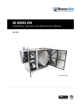
Figure 1: Standard RTF arrangement
Callout Description Callout Description
A Field junction box power connection for
120 V/1 ph/60 Hz
F Lifting lug opening removable plug, Type 4
B Door canopy G 110 V duplex GFI outlet
C Termination bar for roof membrane H Light switch
DRefrigerant connection, order specic I Solid service door
E Approximately 13 in. - -

200.108-IOM (OCT 2022)
Page 8
RTF Rooftop Freezer Systems
Installation
Installation
Installation safety guidelines
Electric
Check the unit nameplate to verify that the power be-
ing provided corresponds with the requirements of the
equipment.
Ensure
that only qualied electricians install
the power supply and xtures, and that they conduct all
electrical work in accordance with local codes.
All electrical conduits entering the RTF enclosure walls
must be non-metalic inside the wall to minimize heat
transfer. After the electrical conductors are run inside
those conduits, thoroughly seal the inside of the conduits
with electrical putty or caulk to prevent moisture migra-
tion. Failure to follow these guidelines may result in the
accumulation of water or ice in the electrical boxes and
conduits inside the RTF.
It is important to congure all power switches and controls
to provide a safe circuit. Poorly installed, maintained, or
wetted machinery could lead to electrical shocks.
Fans
Ensure all fan covers, guards, and shaft retainers, if any,
are in place before applying power to the unit. Always turn
off electrical power and use lock-out/tag-out procedures
before interior inspections, testing, or starting the RTF unit.
Vibration and noise
Immediately stop machinery that emits unusual vibra-
tion or noise. Investigate the source and resolve the issue
before placing the unit back in operation.
Support structure information
The Frick RTF unit consists of the penthouse enclosure
assembly and possibly a roof curb for mounting. You must
anchor these components to a suitable support structure
such as building structural steel or roof decking. Ensure
the structure is capable of supporting the dry shipping
weight of the unit plus any refrigerant within the coil; any
frost or ice that may accumulate on the coil, the weight
of any ancillary items attached to the unit enclosure, such
as electrical panels, and any live loads imposed due to
operating fans and moving air. The weight that the sup-
port structure must support and the associated anchoring
requirements also varies as a result of externally imposed
loads, such as expected snow or ice buildup, seismic, and
wind loading.
Ensure the structure is designed for at least 110% of the
operating weight of the RTF unit distributed as a uni-
form load around the perimeter of the enclosure support
surface.
Ensure the support structure where you are locating the
RTF units is rigid and level, and shim if necessary. Place
shims, as required, at intervals no greater than 3 ft apart
and do not use them to compensate for signicant surface
slope. Ensure the sum total of any individual stack of shims
does not exceed 1/2 in. and only use them to compensate
for surface irregularities.
Secure the RTF unit to the support structure. It is the
installer’s responsibility to ensure the unit is secured in
accordance with applicable building and earthquake codes.
If the support structure is in the form of parallel steel
beams, size the beams in accordance with standard engi-
neering practices.
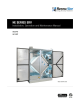
Figure 2: RTF supported directly on building steel
Callout Description Callout Description
A RTF unit D Supporting steel
B Steel base E Roof or insulation, existing
C Load bearing location F Roof ashing and insulation, completed by unit
installers

200.108-IOM (OCT 2022)
Page 9
RTF Rooftop Freezer Systems
Installation
RTF supported by roof curb
Figure 3: RTF supported by roof curb
Callout Description Callout Description
A Penthouse panels C Roof curb upper lip
B Gasket material provided with the roof curb D Roof curb height
Suggested roof to curb nish
Figure 4: Suggested roof to curb nish
Callout Description
A RTF base frame
B Roof curb
C Building steel or roof deck
D Roof insulation, completed by unit installers
ERoof ashing and insulation, completed by
unit installers
F Seal strip, completed by unit installers
Note: Roof ashing to extend up to the seal strip covering
the RTF enclosure to the roof curb joint.
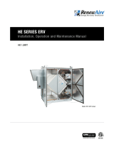
Figure 5: RTF support layout dimensions, in.
Table 1: RTF support layout dimensions, in.
Model A AA B BB
201 88 96 89.5 9 7.5
302 144 152 89.5 9 7.5
422 144 152 93.5 101.5
453 168 176 89.5 97.5
603 168 176 99.5 107.5
703 168 176 99.5 107.5
604 216 224 89.5 9 7.5
734 216 224 93.5 101.5
904 216 224 99.5 107.5
755 243 251 93.5 101.5
905 243 251 99.5 107.5
1005 249.5 257.5 99.5 107.5
1155 249.5 257.5 99.5 107.5
1245 249.5 257.5 99.5 107.5
Note: Dimensions assume 4 in. thick Insulated enclo-
sure panels. Add 2 3/4 in. to the above AA and BB
dimensions if 5 3/8 in. thick panels are used.

200.108-IOM (OCT 2022)
Page 10
RTF Rooftop Freezer Systems
Installation
Roof curb
Preparing the roof curb
Unless specifically indicated on the project drawings, Frick
provides the roof curbs for use with the RTF unit fully as-
sembled.
1. Check the roof curb for any damage that may have oc-
curred during shipment: corner welds, bottom resting
surfaces, upper RTF unit mating surfaces, and anges.
2. Check the roof curb for square by comparing the two
diagonal measurements.
3. Check that the rooftop mounting surface and any
opening in decking and insulation is adequate for ac-
cepting the curb dimensions.
4. Locate the gasket material that is shipped loose with
the curb. Apply this to the curb just before setting the
RTF unit on the curb.
Rigging the roof curb
The roof curb is provided with an interior perimeter ange
that contains slotted holes for attaching the RTF unit to
the roof curb as well as a number of circular holes near
each corner. Use these circular holes to attach rigging
clevises for lifting the curb into place as shown in Figure 6.
Figure 6: Lifting holes in roof curb
Callout Description
A Lifting hole
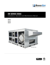
Figure 7: Roof curb load bearing region
Callout Description
A Insulated panels
B Potential stitch weld location
C Support structure
D Load bearing point
NOTICE
If you are not setting the RTF on a roof curb, proceed
to Rigging and lifting the RTF unit.
Setting the roof curb
The roof curb is designed to set directly on support steel.
The load bearing region of the roof curb is the interior
perimeter of the curb as indicated on Figure 7.
The roof curb needs to be supported uniformly around the
entire interior perimeter. Apply shims as necessary. Space
shim packs no more than 36 in. apart and do not exceed
1/2 in. thickness. Do not use shims and blocking to adapt a
curb to roof pitch.
It is the responsibility of the installing contractor to secure
the roof curb to the supporting structure in accordance
with local building codes. If welding is used, place the
light stitch welds along the outside perimeter of the 11
gauge lip as shown in Figure 7. Welding along the inside
perimeter may result in damage to the thermal barrier and
insulation.

200.108-IOM (OCT 2022)
Page 11
RTF Rooftop Freezer Systems
Installation
WARNING
When lifting the RTF unit, weight may not be evenly
distributed causing the unit to be unbalanced or top
heavy. See Figure 10 for recommended lifting proce-
dure.
Rigging and lifting the RTF unit
1. Using the lifting lugs provided, attach spreader bars
and rigging as shown in Figure 10. Spreader bars are
required to prevent damage to the cabinet and pro-
truding components during a lift.
2. Cooling coil is not centered inside the enclosure and is
likely offset the center of mass. Adjust the tension in
each line for the correct load distribution.
Figure 10: Standard rigging conguration
Callout Description
A Lifting point
B Fan side
C Center of gravity, approximate location
D Spreader bar
Lift the air unit only in an upright position. Never lift or
move a unit on its side or upside-down.
3. After the RTF unit can be lifted, remove the protective
sheet metal angles under the perimeter of the enclo-
sure. If mounting the unit on a roof curb, keep the bolts
and nuts because these are required to secure the RTF
unit to the roof curb. See Figure 11. If mounting the
RTF unit directly on structural steel proceed to Setting
the RTF unit without a roof curb.
RTF unit
Preparing the RTF unit
The RTF unit arrives fully assembled as a single unit.
1. Inspect the RTF unit enclosure for any visible damage.
2. The RTF unit is shipped with lifting lugs in place. These
lugs may be used to secure the unit during transport as
well. Check to be sure that all of the lug mounting bolts
are in place and secure before attempting to lift the
unit onto the roof. See the following gure.
Figure 8: Standard lifting lug for mounting bolts
Callout Description
A Standard mounting bolt for the lifting lugs (4)
WARNING
When lifting, use all lifting lugs to avoid damage and/
or personal injury. Lifting lugs are shown in Figure 8.
There are a number of items that may be shipped loose
inside the RTF unit. Identify and inspect these items before
lifting the unit into place. See the following gure.
Figure 9: Ship loose items placed in fan side of RTF

200.108-IOM (OCT 2022)
Page 12
RTF Rooftop Freezer Systems
Installation
Figure 11: Enclosure protective perimeter base
Callout Description
A Protective base
B Base
Note: Store attachment bolts and nuts inside the base
CAUTION
If you do not rig or lift the unit carefully, you could
damage the unit, hurt yourself or others.
Setting the RTF unit
1. When setting the RTF unit on a roof curb, rst apply
two strips of 1 7⁄8 in. wide neoprene gasket material
around the top surface of the roof curb. Position the
inside strip of gasket material a third of the way inside
the load bearing point of the mating surface. Ensure
the outside strip is approximately 1/4 in. from the out-
side edge of the curb nailer. See the following gure.
Figure 12: Applying roof curb gasket
Callout Description
A Two 1 7/8 in. x 1/2 in. neoprene gaskets
B Support structure
C Load bearing point
2. As the RTF unit is being positioned overhead, it may
be benecial to spray the neoprene gasket with a light
mist of water. This allows slight adjustments while the
RTF unit is aligned for nal positioning. The use of drift
pins also facilitates positioning the RTF unit on the
roof curb so that the attachment bolts can be installed
easily.
3. Install the ange bolts around the inside perimeter
ange. Insert the bolts downward with the nuts being
installed on the bottom side of the ange. Space the
attachment bolts uniformly around the inside perim-
eter ange with no more than 14 in. between adjacent
bolts. See Figure 3 and Figure 6.
Setting the RTF unit without a roof curb
1. When setting the RTF unit without a roof curb it is
unnecessary to apply a sealing gasket. The RTF base
structure may be set directly on supporting steel.
2. The RTF base needs to be supported uniformly around
the entire interior perimeter. Apply shims as necessary.
Space shim packs no more than 36 in. apart and do not
exceed 1/2 in. thickness. Do not use shims and blocking
to adapt the RTF base to a pitched roof.
Figure 13: RTF set directly on site structural steel
Callout Description
A Factory-supplied bolt holes
B Insulated panels
C Load bearing point
D Support structure
E Potential weld location
3. It is the responsibility of the installing contractor to
secure the RTF unit base to the supporting structure in
accordance with local building codes. If welding, place
light stitch welds along the inside perimeter of the base
lip as shown in Figure 13. Alternatively, the interior
base lip also has factory-supplied holes through which
bolts may be used to secure the unit.

200.108-IOM (OCT 2022)
Page 13
RTF Rooftop Freezer Systems
Installation
Installing optional sloped roof paneling
For sloped roof applications, refer to the suppliers
instructions for installing sloped roof paneling, which you
install before the roof membrane.
Installing the roof membrane
You must protect the RTF units with a membrane roof
cover, which consists of the following components:
• Membrane roof cover
• Termination trim, plastic
• Black Phillips head metal screws
• 2 in. truss plates
• Caulking
Before you install the membrane, keep the following points
in mind:
CAUTION
The membrane is very slippery when wet.
• Keep sharp objects such as nails or screws off the
roof. Someone stepping on them could puncture the
membrane.
• Do not allow hot objects to touch the membrane.
• You can temporarily repair any punctures or holes that
occur during installation with duct tape or caulking.
However, you need to make any nal repairs using a
heat gun.
For correct weather protection, complete the following
steps:
1. Unpack the membrane roll, being careful not to cut the
membrane.
2. Unroll the membrane over the roof area, ensuring the
tabs are on the underside and that the roof area is free
of debris.
3. Maneuver or shift the membrane so it ts squarely over
the roof area, allowing equal amounts of membrane
to overhang at least 6 in. on the edges of the roof. In
windy conditions, place a heavy object, such as con-
crete blocks or tires, around the perimeter to keep the
wind from lifting the membrane.
4. After centering the membrane on the roof, either fold
or roll the membrane back towards the center of the
roof so the underside tabs are exposed. The roll or fold
must be parallel to the factory seam and tab.
5. Stop rolling or folding when you reach the tab going in
the opposite direction.
6. Begin to roll or fold the membrane back until a tab is
exposed and the tab is at on the roof deck.
7. Install the 2 in. truss plates along the fastening tab us-
ing the Black Philips screws, keeping them spaced 12
in. O.C.
Note: Do not screw directly over a ceiling panel seam.
Stay 6 in. away from any of these seams.
8. Continue to roll the membrane until the next tab is
exposed and in place, ready for fastening.
9. Pull the tab tightly to reduce any wrinkle that may oc-
cur. After pulling the tab, hold it in position until you
can secure it with a couple of fasteners.
10. Install the fasteners along the tab 12 in. O.C.
11. Complete steps 9 and 10 for every tab.
12. Hold the membrane that is overhanging the edge of the
roof tight and install the termination bar at least 5 in.
below the horizontal roof. If the termination bar has a
caulking lip, ensure the lip is on the upside.
13. Fasten the termination bar using the pilot holes with
the Black Philips head screws.
Figure 14: Fastening the termination trim
14. After attaching all termination bars, trim any excess
membrane that is exposed under the termination bar
with a sharp knife, using the bottom edge of the bar as
a cutting guide.
15. Caulk the top edge of the termination bar.

200.108-IOM (OCT 2022)
Page 14
RTF Rooftop Freezer Systems
Installation
Callout Description Callout Description
A Fastening tab F Factory welds, staggered equidistant
between factory welds of adjacent roles
27 in. O.C.
B Approved fastener with barbed stress plate G Approved fastener with barbed stress plate
approximately 27 in. O.C.
C Factory weld H Side lap roll to roll minimum 4 1/2 in.
D Paneled roll I Side lap
E Factory tab - -
Figure 15: Membrane roll out and fastener placement

200.108-IOM (OCT 2022)
Page 15
RTF Rooftop Freezer Systems
Installation
Sealing the RTF enclosure
The RTF enclosure insulated panels may have shifted dur-
ing transit. It is important to inspect all panel seams and
reset the cam-locks as necessary.
1. Inspect all panel seams to ensure that the sealing gas-
ket is visibly compressed. If it is not, remove the snap
plugs at the cam-lock, use an allen wrench to com-
pletely unlock the cam latch and then reset and relock
it. Reinstall the snap plugs.
2. Inspect all panel corners to be sure that adjacent pan-
els are not racked; loosen the required cams, adjust the
panels then reset and relock the cam-locks.
3. Although the RTF enclosure is completely sealed when
assembled at the factory, additional caulk may be
required on either interior and exterior panel seams.
Frick suggests the use of a silicone DOW RTV-732 food
grade caulk for any interior seams. Use rainbuster 1200
for resealing any external seams.
4. Use caulking or insulating sealant to nish the exterior
joint between the RTF enclosure and the roof curb
before the surrounding roong is sealed to the unit
5. Inspect each of the RTF enclosure freezer door rain
hoods. Tighten any loose attachment screws and caulk
as necessary.
6. Remove all of the lifting lugs by removing the mounting
bolts in each one. Discard the lifting lugs and bolts.
7. Insert the lifting lug plug into the opening. Take care
not to damage the inner and outer seal strips. Attach
the plug into place using the screws provided. Plug all
of the factory-drilled screw holes.
8. Seal the building roof insulation to the RTF enclosure
or the roof curb. Use a cant or radius around the pe-
rimeter of the enclosure or curb.
For installations involving a roof curb, it is necessary to
use roof membrane or ashing to cover the exterior of the
curb including the curb to RTF enclosure joint. Ensure the
nal nish includes a caulked seal strip as shown in Figure
4.
If you don't use a roof curb, the location of the seal strip
is subject to the discretion of the installer that installs and
seals the roof.
Figure 16: Lifting lug enclosure plug
11 in.
1 1/2 in.
16 in.
Callout Description
A1/8 in. pre-drilled holes for eld mounting
B White stucco aluminum cover plate
C Double-beaded gasket
D High-density urethane perimeter

200.108-IOM (OCT 2022)
Page 16
RTF Rooftop Freezer Systems
Installation
Discharge air plenum
The discharge air plenum and interconnecting circular
ducts components ship separately from the RTF unit.
It is intended that the RTF discharge air plenum be sup-
ported independently of the RTF unit or its supporting roof
curb.
Preparing the discharge plenum
1. Inspect the air discharge plenum for any obvious ship-
ping damage.
2. Install a prefabricated circular duct transition to each
plenum air inlet orice using tapper screws. The RTF
fans are provided with a transition duct attachment.
See Figure 17.
Figure 17: Fan discharge nozzle integral to module
3. The interconnecting duct material is provided as pieces
of at stock. Take one piece of at stock, roll it into a
tube that is approximately 33 in. in diameter. Secure it
with a strap to prevent it from unrolling. Stand the roll
inside one of the plenum air inlet openings. Repeat this
process for each fan discharge duct.
Installing the discharge plenum
1. Lift the plenum into position taking care that the coiled
duct material does not get damaged. Mount the
plenum using support rods as indicated on the Frick
RTF plenum drawing. See Figure 18 for an example.
Note that each plenum hanger rod must pass through
the upper alignment bracket and support the assem-
bly by the lower bracket. Use the double nuts jammed
together to secure the nal adjustment.
2. Each fan discharge must be connected to the plenum
using the coiled at stock material. Carefully measure
the distance between the RTF fan discharge nozzle and
the plenum transition duct inlet. Mark the outside of
the coiled duct at stock so that approximately 50%
of the excess is available for insertion and attachment
into the fan discharge nozzle. Ensure that the remaining
50% is available to extend into the plenum transition
for attachment.
3. Carefully lift the coiled duct material and insert it into
the fan discharge nozzle. Allow it to uncoil and attach
it to the fan nozzle using tapper screws. Install screws
spaced approximately 18 in. apart.
4. Attach the coiled duct material to the lower plenum
duct transition assembly using tapper screws, again
spaced approximately 18 in. apart.
5. Secure the vertical duct seam using tapper screws
spaced a maximum of 12 in. apart.
Figure 18: Discharge plenum assembly
Callout Description
A Transition duct assembly
B Discharge plenum

200.108-IOM (OCT 2022)
Page 17
RTF Rooftop Freezer Systems
Installation
Figure 20: Standard RTF enclosure indicating 120 V eld power connection
Callout Description Callout Description
A Field junction box power connection for
120 V/1 ph/60 Hz
D Light switch
B Door canopy E Solid service door
C 110 V duplex GFI outlet
Electrical
The Frick RTF unit may be provided with a variety of
factory power wiring options. See Figure 19 for an ex-
ample.
• Fan motors are not factory wired
• Fan motors wired to a disconnect
• Fan motors factory wired to an ATL starter
• Fan motors factory wired to a VFD
See Figure 21 and Figure 22 for standard suggestions
for wiring multiple parallel fans. When power wiring the
fans on the installation site, it is the installing contrac-
tor’s responsibility to ensure that the electrical design and
installation meet the applicable codes.
For RTF units with factory wired motors, refer to the
order-specic wiring drawings provided.
120 V service power
Each Frick RTF units is provided with internal lights,
exterior light switches and external convenience outlets
located by each access door. For RTF units designed to
operate below 32°F, the access door seals are also heat
traced. Each access door and associated components are
internally wired and require 120 V eld supplied power to
an external electrical junction box. See Figure 20.
Figure 19: Standard RTF 120 V factory-installed service
wiring diagram
BRONZE TERMINAL
(120 VAC/60 Hz/1Ø POWER)
(GROUND FAULT
CIRCUIT INTERRUPTER)
DOOR
HEAT ER
BACK VIEW
LOAD
GREEN
GRAY
GRAY
DOOR
FRAME
HEAT ER
SILVER TERMINAL
(NEUTRAL)
LINE
GFCI
BLACK
WHITE
SINGLE
EXTERIOR
SWITCH
RED
WHITE
BLACK
GREEN
VAPOR PROOF
LIGHTON
DOOR FRAME
BLACK
GREEN
WHITE
WHITE
GREEN
TAN
RED
GREEN
WHITE
WHITE
BLACK
GREEN GREEN
BLACK
WHITE
FIELD CONNECT
120VAC/60 Hz/1Ø
#12 AWGTHHN STRANDED Cu
GRAY
GRAY
FIELD CONNECTION BOX
Note: Two independent circuits for each RTF unit, standard
NOTICE
The electrical specications information provided
here is standard for each of two tie-in points, one for
each side of the RTF enclosure.

200.108-IOM (OCT 2022)
Page 18
RTF Rooftop Freezer Systems
Installation
Figure 21: Standard power wiring involving ATL starters
Figure 22: Standard power wiring involving a VFD
Electrical Specifications
120VAC/60 Hz/1Ø
Light and heated door frame
FLA 2.4 amps
GFCI rating
20 amps
Factory-installed wire
#12 AWG THHN stranded Cu
Figure 23: Electrical specications

200.108-IOM (OCT 2022)
Page 19
RTF Rooftop Freezer Systems
Installation
Refrigeration
The Frick RTF unit may be provided with a cooling coil de-
signed for any direct or secondary refrigerant. Refer to the
original order documentation for specic information.
The RTF cooling coil is provided with a nitrogen charge.
This charge prevents moisture from migrating inside the
refrigerant circuits, collecting and contaminating the future
cooling system.
CAUTION
Care must be taken when initially opening the ends
of the refrigerant pipes to make eld connections
as injury could occur due to the positive nitrogen
charge.
NOTICE
Once the cooling coil refrigerant piping has been
opened, maintain a dry nitrogen charge in the pip-
ing system if the coil is not charged with refriger-
ant immediately. Failure to do so could result in the
collection of moisture inside the coil circuits and
the possible contamination of the future refrigerant
charge.
Refrigerant piping
CAUTION
The unit connections are not designed to support the
weight of piping, valves, or ttings.
The cooling coil refrigerant connections are weldable pipe
stubs, anges, or threaded pipe caps. The project submit-
tal drawings indicate the coil connections for a specic
unit. It is important to correctly size and orientate the
refrigerant lines servicing the cooling coil in order for the
coil to function correctly.
Refrigeration piping design and line size selection are the
responsibility of the unit installers. Conrm that the system
design parameters comply with the coil design parameters
stated on the certied submittal drawings. Before con-
necting the refrigerant lines to the coil, verify that the pip-
ing and control valves on the unit are correctly supported.
Design all piping to minimize the transfer of vibration to
the unit and allow for thermal expansion of piping.
CAUTION
Avoid hydraulic lockup caused by trapped liquid.
When there is an increase in ambient temperature
around conned liquid, the expansion pressure could
cause refrigerant lines to burst.
When the Frick RTF unit is provided with hot gas drain pan
heat, the pan coils are not factory piped to the evaporator
refrigeration piping. Design of the refrigerant control valve
group and the interconnecting pan and coil piping must
be done by a qualied refrigeration engineer. The required
refrigeration piping must be done in the eld by qualied
pipe tters.
CAUTION
Use of a refrigerant other than that stamped on the
nameplates may cause damage to the refrigeration
coils. Coils must not be subjected to higher pressure
than the design pressure stamped on the nameplate.
In ammonia systems, be sure to use refrigerant
grade, not agricultural grade ammonia.
Flooded surge vessels support
The Frick RTF enclosure and pipe stubs are not designed
to support a ooded surge vessel. A separate support
structure is required for ooded evaporator applications.
Evaporator condensate drain piping
The cooling coil condensate drain pan is provided with a
male pipe thread (MPT) pipe stub out the end of the pan
and extending through the RTF enclosure.
Although the height may vary from model to model, in
general the drain pan drain connection is centered ap-
proximately 13 in. above the bottom of the RTF enclosure
panels. If the unit is mounted on a roof curb, this is ap-
proximately 13 in. above the top of the roof curb.
Due to static pressures inside the RTF unit enclosure, it is
necessary to trap the condensate drain. This is generally
done with a P-trap. It is the responsibility of the installing
contractor to be sure that the condensate water is piped
according to applicable codes.
Figure 24: MPT condensate drain
Callout Description
A Drain pan drain connection
NOTICE
When mounting a Frick RTF unit directly on building
steel, be sure to allow enough elevation to properly
trap the condensate drain pipe. See the project sub-
mittal drawings for available height.
RTF units are designed for freezer applications and may be
installed in climates that have low outdoor temperatures
during the winter. If either of these conditions apply it is
advisable to provide heat trace of the condensate drain
piping. Consult a refrigeration design engineer for selec-
tion and application of the heat trace product.

200.108-IOM (OCT 2022)
Page 20
RTF Rooftop Freezer Systems
Operation
Operation
Start-up
Before start-up
Do not start the unit until the following you inspect and
verify operational readiness. You can avoid accidents or
equipment failure by rectifying any unsatisfactory
condition.
WARNING
Do not attempt any inspections or maintenance un-
less the electrical power to the fans has been com-
pletely disconnected and locked out.
1. Inspect the general condition of the unit:
• Enclosure integrity: ensure that the seams are all
sealed, the doors operate and seal correctly, and the
roof membrane is correctly installed.
• RTF unit is secured correctly, roof curb, if used, is
secured correctly
• Discharge air plenum and ducts are secured and
installed correctly
2. Inspect fans and motors for condition and alignment:
• Verify that all fan mounting bolts are secure and all
fan motor mounting bolts are tight.
• Rotate fans by hand to ensure rotation free of ob-
struction.
• Verify the rotation of the fans
3. Clean up any excessive dust or remains of material
used during installation:
• Inside the drain pan
• Top of the cooling coil housing
• Inside of the discharge air plenum
4. Check the refrigerant pipe penetrations of the RTF
enclosure wall and the pipe insulation:
• Pipe insulation is sealed
• Pipe insulation to the RTF enclosure interface is
sealed correctly
• Check the cooling coil ns. Use a n comb to
straighten any bent ns that may block air ow.
5. Touch up scratches in galvanizing with cold galvanized
paint.
WARNING
Do not allow the access door heat tape to be en-
ergized unless the freezer / cooler refrigeration is
operating. Allowing the heat tape to be energized
without cooling inside the RTF unit may allow the
heat tape to overheat and destroy itself.
WARNING
Do not remove safety equipment or warning labels
from equipment. Removal could result in serious
injury or death.
NOTICE
When starting the RTF unit, due to the RTF enclosure,
the temperature pull-down rate is unrestricted down
to 45°F. Below 45°F, restrict the temperature pull-
down rate to 10°F per 24-hr period.
/