Page is loading ...

RELAMPING INSTRUCTIONS
FOR FRONT ACCESS LIGHTS
RELAMPING INSTRUCTIONS
FOR FRONT ACCESS LIGHTS
RELAMPING INSTRUCTIONS
FOR FRONT ACCESS LIGHTS
RELAMPING INSTRUCTIONS
FOR FRONT ACCESS LIGHTS
1. Disconnect the power to the spa or bath before relamping.
2. Drain the spa or bath until it is completely empty.
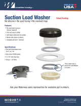
3. To remove lens, position the front access wrench over the front access light in
such a way that both the wall fitting and the lens splines engage.
4. While holding the outer part of the front access
wrench firmly and free of rotation, turn the center
part of the relamping tool clock-wise to unscrew
the lens.
5. Replace lamp with type 912 bulb only.
6. Inspect o-ring to make sure that it is free of damage and is properly
positioned in the o-ring groove before replacing lens. Note: Contact a
qualified service personnel if a replacement o-ring is needed.
7. To replace lens, gently screw the lens into the wallfitting finger tight.
8. Position relamping tool over front access light so that both the wallfitting and
the lens splines engage.
9. While holding the outer part of the relamping tool firmly and free of rotation,
turn the center part of the tool counter-clockwise until rotation comes to a
stop. Do not over tighten!
1. Disconnect the power to the spa or bath before relamping.
2. Drain the spa or bath until it is completely empty.
3. To remove lens, position the front access wrench over the front access light in
such a way that both the wall fitting and the lens splines engage.
4. While holding the outer part of the front access
wrench firmly and free of rotation, turn the center
part of the relamping tool clock-wise to unscrew
the lens.
5. Replace lamp with type 912 bulb only.
6. Inspect o-ring to make sure that it is free of damage and is properly
positioned in the o-ring groove before replacing lens. Note: Contact a
qualified service personnel if a replacement o-ring is needed.
7. To replace lens, gently screw the lens into the wallfitting finger tight.
8. Position relamping tool over front access light so that both the wallfitting and
the lens splines engage.
9. While holding the outer part of the relamping tool firmly and free of rotation,
turn the center part of the tool counter-clockwise until rotation comes to a
stop. Do not over tighten!
HOLD FIRM
ROTATE CW
HOLD FIRM
ROTATE CW
HOLD FIRM
ROTATE CW
HOLD FIRM
ROTATE CW
810-0005.0618
©2018 Waterway Plastics
2200 East Sturgis Road, Oxnard CA 93030 • Phone 805.981.0262 • Fax 805.981.9403
www.waterwayplastics.com • [email protected]
Designed,
Engineered &
Manufactured
in the USA.
810-0005.0618
©2018 Waterway Plastics
2200 East Sturgis Road, Oxnard CA 93030 • Phone 805.981.0262 • Fax 805.981.9403
www.waterwayplastics.com • [email protected]
Designed,
Engineered &
Manufactured
in the USA.
810-0005.0618
©2018 Waterway Plastics
2200 East Sturgis Road, Oxnard CA 93030 • Phone 805.981.0262 • Fax 805.981.9403
www.waterwayplastics.com • [email protected]
Designed,
Engineered &
Manufactured
in the USA.
810-0005.0618
©2018 Waterway Plastics
2200 East Sturgis Road, Oxnard CA 93030 • Phone 805.981.0262 • Fax 805.981.9403
www.waterwayplastics.com • [email protected]
Designed,
Engineered &
Manufactured
in the USA.

FRONT ACCESS
INSTALLATION INSTRUCTIONS
FRONT ACCESS
INSTALLATION INSTRUCTIONS
FRONT ACCESS
INSTALLATION INSTRUCTIONS
FRONT ACCESS
INSTALLATION INSTRUCTIONS
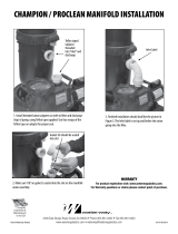
1. Mount lens wallfitting on a vertical wall at least 3" below normal water level
and within a maximum depth of 40". The lens assembly should be mounted in
such a way so that relamping cannot be accomplished by occupant of spa or
bathtub (the minimum reach path distance must be 5 ft. from the rim of the tub
at its closest point to the lamp housing). The most appropriate location would
be near where normal maintenance of pumps and heaters, etc., would occur.
2. Drill a 2 ½" diameter hole for 3" spa lights. Drill a 3 ¾" diameter hole for
5" spa lights.
3. Clear away any insulation or foam filling around the hole that may obstruct
ventilation of light and application of unit.
4. Place the lens assembly sealing gasket between the tub well and the lens
wallfitting on the water side of the tub. Silicone may be added if desired.
5. Screw the nut on from the back and tighten firmly. Use self adjustment ring
with 5" spa lights.
6. Mount the transformer enclosure so that the drain hole points down.
7. Route the two (2) low voltage wires away from grounded metal parts of the
pump, heater, plumbing components and isolated metal parts exposed to the
occupants of the tub.
8. Lock the light bulb into the bulb retainer and screw the light bulb retainer
onto the back of the lens wallfitting.
810-0005.0618
©2018 Waterway Plastics
WARRANTY
For product registration visit: www.waterwayplastics.com.
For Warranty questions or claims please contact point of purchase.
WARRANTY
For product registration visit: www.waterwayplastics.com.
For Warranty questions or claims please contact point of purchase.
WARRANTY
For product registration visit: www.waterwayplastics.com.
For Warranty questions or claims please contact point of purchase.
WARRANTY
For product registration visit: www.waterwayplastics.com.
For Warranty questions or claims please contact point of purchase.
810-0005.0618
©2018 Waterway Plastics
810-0005.0618
©2018 Waterway Plastics 810-0005.0618
©2018 Waterway Plastics
/