Page is loading ...

1 7021-154A 7/9/2014
CASTILE-B PELLET STOVE
Model(s):
CASTILE-MBK-B
CASTILE-CWL-B
CASTILE-CSB-B
CASTILE-PMH-B
Installation Manual
Installation & Appliance Set-Up
INSTALLER: Leave this manual with party responsible for use and operation.
OWNER: Retain this manual for future reference.
NOTICE: DO NOT DISCARD THIS MANUAL
O-T L
Tested and
Listed by Portland
Oregon USA
OMNI-Test Laboratories, Inc.
CUS
WARNING
If the information in these instruc-
tions is not followed exactly, a
fi re could result causing property
damage, personal injury, or death.
• Do not store or use gasoline or other fl am-
mable vapors and liquids in the vicinity of
this or any other appliance.
• Do not overfi re - If heater or chimney con-
nector glows, you are overfi ring. Overfi ring
will void your warranty.
• Comply with all minimum clearances to
combustibles as specifi ed. Failure to
comply may cause house fi re.
HOT SURFACES!
Glass and other surfaces are hot
during operation AND cool down.
Hot glass will cause burns.
• Do not touch glass until it is cooled
• NEVER allow children to touch glass
• Keep children away
• CAREFULLY SUPERVISE children in same room as
fi replace.
• Alert children and adults to hazards of high temperatures
• High temperatures may ignite clothing or other
fl ammable materials.
• Keep clothing, furniture, draperies and other fl ammable
materials away.
WARNING
CAUTION
Tested and approved for wood pellets or shelled corn only.
Burning of any other type of fuel voids your warranty.
NOTE
To obtain a French translation of this manual, please contact
your dealer or visit www.quadrafi re.com
Pour obtenir une traduction française de ce manuel, s’il vous
plaît contacter votre revendeur ou visitez www.quadrafi re.com
CAUTION
Check building codes prior to installation.
• Installation MUST comply with local, regional, state and na-
tional codes and regulations.
• Consult local building, fi re offi cials or authorities having juris-
diction about restrictions, installation inspection, and permits.

2 7021-154A 7/9/2014
CASTILE FREESTANDING
TABLE OF CONTENTS
Safety Alert Key:
• DANGER! Indicates a hazardous situation which, if not avoided will result in death or serious injury.
• WARNING! Indicates a hazardous situation which, if not avoided could result in death or serious injury.
• CAUTION! Indicates a hazardous situation which, if not avoided, could result in minor or moderate injury.
• NOTICE: Indicates practices which may cause damage to the appliance or to property.
1 Important Safety Information ............3
A. Appliance Certifi cation ......................................................3
B. BTU & Effi ciency Specifi cations........................................3
C. Glass Specifi cations .........................................................3
D. Electrical Rating................................................................3
E. Mobile Home Approved .................................................... 3
2 Getting Started ...................................4
A
.
Design, Installation & Location Considerations ..........................4
B. Thermostat Wall Control Location......................................5
C. Tools And Supplies Needed ..............................................5
D. Inspect Appliance and Components .................................5
E. Install Checklist ..................................................................6
3 Dimensions and Clearances .............7
A. Appliance Dimensions ......................................................7
B. Clearances to Combustibles (UL and ULC) .......................8
C. Hearth Pad Requirements (UL and ULC) ..........................8
4 Vent Information .................................9
A. Venting Termination Minimum Requirements ...................9
B. Avoiding Smoke and Odors ..............................................10
C. Negative Pressure ............................................................10
D. Draft .... .............................................................................11
E. Chimney and Exhaust Connection ..................................11
F. Venting Termination Requirements ...................................11
G. Equivalent Feet of Pipe ...................................................12
H. Pipe Selection Chart ........................................................12
I. Pellet Venting Charts..........................................................13
5 Venting Systems ..............................14
A. Alcove...... .........................................................................14
B. Through The Wall .............................................................15
C. Vertical into Existing Class A Chimney .............................16
D. Through The Wall & Vertical - Exterior ..............................16
E. Vertical - Interior - Typical Installation ................................16
F. Masonry.............................................................................17
G. Alternate Masonry ............................................................17
6 Appliance Set-Up .............................18
A. Outside Air Kit Instructions ................................................18
B. Top Vent Adapter Installation ............................................19
C. Rear Vent & Rear Vent to Top Vent Adapter Installation ...19
D. Leg Leveling System ........................................................19
E. Optional Log Set Placement Instructions ..........................20
F. Thermostat Installation ......................................................20
7 Mobile Home Installation .................21
8 Accessory List .................................22

7/9/2104 7021-154A 3
CASTILE FREESTANDING
Model Castile Pellet Stove
Laboratory OMNI Test Laboratories, Inc.
Report No. 061-S-77d-6.2
Type Solid Fuel Room Heater/Pellet Fuel
Burning Type
Standard ASTM E1509-04, ULC S627-00 and
ULC/ORD-C1482-M1990 Room Heater
Pellet Fuel Burning type and (UM)
84-HUD, Mobile Home Approved.
FCC Complies with Part 15 of FCC Rules.
Operation is subject to the following
two conditions: (1) this device may not
cause harmful interference, and (2) this
device must accept any interference
received, including interference that may
cause undesired operation.
EPA Certifi ed: 1.8 grams per hour
Effi ciency: 78%
EPA BTU Output: 8,500 - 28,200 / hr
Heating Capacity: up to 1,500 square feet depend-
ing on climate zone
Hopper Capacity: 40 lbs +/- 5 lbs
Vent Size: 3” or 4” L or PL
Fuels: Pellets or Shelled Corn
Shipping Weight: 258 lbs
1 Important Safety Information
NOTE: Hearth & Home Technologies, manufacturer of
this appliance, reserves the right to alter its products, their
specifi cations and/or price without notice.
Improper installation, adjustment, alteration, service or
maintenance can cause injury or property damage.
For assistance or additional information, consult a qualifi ed
installer, service agency or your dealer.
Quadra-Fire is a registered trademark of Hearth & Home
Technologies.
• Installation and use of any damaged appliance.
• Modifi cation of the appliance.
• Installation other than as instructed by Hearth & Home
Technologies.
• Installation and/or use of any component part not approved by
Hearth & Home Technologies.
• Operating appliance without fully assembling all components.
• Operating appliance without legs attached (if supplied with unit).
• Do NOT Overfi re - If appliance or chimney connector glows,
you are overfi ring.
Any such action that may cause a fi re hazard.
WARNING
Fire Risk.
Hearth & Home Technologies disclaims any
responsibility for, and the warranty will be voided by,
the following actions:
D. Electrical Rating
115 VAC, 60 Hz, Start 4.1 Amps, Run 1.1 Amps
E. Mobile Home Approved
• This appliance is approved for mobile home installa-
tions when not installed in a sleeping room and when
an outside combustion air inlet is provided.
• The structural integrity of the mobile home fl oor, ceil-
ing, and walls must be maintained.
• The appliance must be properly grounded to the
frame of the mobile home and use only Listed pellet
vent Class “L” or “PL” connector pipe.
• Outside Air Kit, part OAK-ACC must be installed in a
mobile home installation.
NOTICE: This installation must conform with local codes. In
the absence of local codes you must comply with the ASTM
E1509-04, ULC S627-00, (UM) 84-HUD and ULC/ORD-
C-1482.
*BTU will vary, depending on the type of fuel you use in your
appliance. Consult your Quadra-Fire dealer for best results.
These heaters meet the US Environmental Protection
Agency’s Emission limits for pellet heaters. Under specifi c
conditions the Castile stove has shown to deliver heat at rates
ranging from 8,500 to 28,200 BTU/hr.
Meets EPA particulate matter (smoke) control requirements
for non catalytic wood heaters built on or after July 1,1990.
C. Glass Specifi cations
This stove is equipped with 5mm ceramic glass. Replace
glass only with 5mm ceramic glass. Please contact your
dealer for replacement glass.
A. Appliance Certifi cation
B. BTU & Effi ciency Specifi cations

4 7021-154A 7/9/2014
CASTILE FREESTANDING Install Guide
2 Getting Started
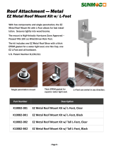
Marginal Location:
• Below peak
Location NOT recommended:
• Not the highest point of the roof
• Wind loading possible
Multi-level Roofs
Windward
Leeward
Recommended:
Outside Air Intake
on windward side
NOT recommended:
Outside Air Intake
on leeward side
Recommended Location:
• Above peak
Recommended:
• Insulated exterior chase
in cooler climates
Recommended Location:
• Above peak
• Inside heated space
Location NOT recommended:
• Too close to tree
• Below adjacent structure
• Lower roof line
• Avoid outside wall
Marginal Location:
• Wind loading possible
Figure 4.1
A
.
Design, Installation & Location Considerations
1. Appliance Location
NOTICE: Check building codes prior to installation.
• Installation MUST comply with local, regional, state and
national codes and regulations.
• Consult insurance carrier, local building inspector, fi re
offi cials or authorities having jurisdiction over restrictions,
installation inspection and permits.
It is a good idea to plan your installation on paper, using exact
measurements for clearances and fl oor protection, before
actually beginning the installation. Location of the appliance
and chimney will affect performance.
Consideration must be given to:
• Safety, convenience, traffi c fl ow
• Placement of the chimney and chimney connector and to
minimize the use of chimney offsets.
• Place the appliance where there will be a clear passage
for a Listed chimney through the ceiling and roof (vertical)
or through exterior wall (horizontal).
• Installing the required outside air kit will affect the location
of the vent termination.
When locating vent and venting termination, the ideal loca-
tion is to vent above roof line when possible. This minimizes
the affects of wind loading.
Since pellet exhaust can contain ash, soot or sparks, you
must consider the location of:
• Windows
• Air Intakes
• Air Conditioner
• Overhang, soffi ts, porch roofs, adjacent walls
• Landscaping, vegetation
• Horizontal or vertical vent termination
2. Floor Support
The supporting fl oor under the appliance must be able to
handle the weight of the appliance, fuel load and the weight
of the chimney.
Ensure that your fl oor will support these weights prior to
installation. Add suffi cient additional support to meet this
weight requirement prior to installation. The weight of the
appliance is 258 lbs.
WARNING
Fire Risk.
Damaged parts could impair safe operation. Do
NOT install damaged, incomplete or substitute
components.

7/9/2104 7021-154A 5
CASTILE FREESTANDING
• Installation and use of any damaged
appliance.
• Modifi cation of the appliance.
• Installation other than as instructed by Hearth & Home
Technologies.
• Installation and/or use of any component part not approved
by Hearth & Home Technologies.
• Operating appliance without fully assembling all components.
• Operating appliance without legs attached (if supplied with
unit).
• Do NOT Overfi re
Or any such action that may cause a fi re hazard.
WARNING
Hearth & Home Technologies disclaims any
responsibility for, and the warranty will be
voided by, the following actions:
Reciprocating Saw Channel Locks
Hammer Phillips Screwdriver
Tape Measure Plumb Line
1/4” Self-Tapping Screws Framing Material
Hi-temp Caulking Material Gloves
Safety Glasses Framing Square
Electric Drill & Bits (1/4”) Level
May also need:
Vent Support Straps Venting Paint
Tools and building supplies normally required
for installation, unless installing into an existing
masonry fi replace:
C. Tools And Supplies Needed
B. Thermostat Wall Control Location
The thermostat wall control’s location will have some affect
on the appliance’s operation.
• Maximum wire length from appliance is 100 feet (30.48m)
continuous unspliced wire. Recommended 20 gauge wire,
solid copper .
• When located close to the appliance, it may require a
slightly higher temperature setting to keep the rest of the
house comfortable.
• When located in an adjacent room or on a different fl oor
level, you will notice higher temperatures near the appli-
ance.
D. Inspect Appliance and Components
• Open the appliance and remove all the parts and articles
packed inside the Component Pack. Inspect all the parts
and glass for shipping damage.
• Report to your dealer any parts damaged in shipment.
•
All labels have been removed from the glass door.
•
Plated surfaces have been wiped clean with a soft cloth,
if applicable.
• Read all the instructions before starting the installation.
Follow these instructions carefully during the
installation to ensure maximum safety and benefi t.
• Follow pipe manufacturer instructions for installation
and air clearance requirements.
WARNING
Fire Risk.
Damaged parts could impair safe operation.
Do NOT install damaged, incomplete or
substitute components.

6 7021-154A 7/9/2014
CASTILE FREESTANDING
ATTENTION INSTALLER:
Follow this Standard Work Checklist
This standard work checklist is to be used by the installer in conjunction with, not instead of, the instructions contained in this installation manual.
Customer:
Date Installed:
Lot/Address:
Location of Fireplace:
Installer:
Dealer/ Distributor Phone #:
Serial #:
Model (circle one): CASTILE-MBK-B CASTILE-CWL-B CASTILE-CSB-B CASTILE-PMH-B
WARNING! Risk of Fire or Explosion! Failure to install fi replace according to these instructions can lead to a fi re or explosion.
Appliance Install
Verifi ed clearances to combustibles. (Pg. 8)
Fireplace is leveled and liner is secured to appliance. (Pg. 19)
Outside air kit installed. (Pg. 18)
Floor protection requirements have been met.
The masonry chimney is inspected by a professional and is clean or the
factory built metal chimney is installed according to the manufacturer’s
instructions and clearances.
Chimney Section 4 (Pg. 11)
Chimney confi guration complies with diagrams.
Chimney installed, locked and secured in place with proper clearance.
Chimney meets the minimum height requirements.
Roof fl ashing installed and sealed.
Terminations installed and sealed.
Clearances Section 3 (Pg. 7)
Combustible materials not installed in non-combustible areas.
Verifi ed all clearances meet installation manual requirements.
Mantels and wall projections comply with installation manual requirements.
Protective hearth strips and hearth extension installed per manual requirements.
Appliance Setup Section 5 (Pg. 18)
All packaging and protective materials removed.
Firebrick, baffl e and ceramic blanket installed correctly.
All labels have been removed from the door.
All packaging materials are removed from inside/under the fi replace.
Manual bag and all of its contents are removed from inside/under the fi replace
and given to the party responsible for use and operation.
Hearth & Home Technologies recommends the following:
• Photographing the installation and copying this checklist for your fi le.
• That this checklist remain visible at all times on the fi replace until the installation is complete.
Comments: Further description of the issues, who is responsible (Installer/Builder/Other Trades, etc.) and corrective action needed:
Comments communicated to party responsible by on
(Builder/Gen. Contractor) (Installer) (Date)
Part # 4017-254 • Rev B • 01/29/13
YES IF NO, WHY?
E. Install Checklist

7/9/2104 7021-154A 7
CASTILE FREESTANDING
Figure 7.2- Front View
Figure 7.1 - Top View
Figure 7.3 -Side View Figure 7.4 - Side View with Top Vent Adapter
24 in. (609mm)
24-5/8 in.
(626mm)
12 in.
(305mm)
24 in. (609mm)
28-9/16 in.
(725mm)
15-15/16 in.
(405mm)
22-7/8 in.
(582mm)
17 in.
(431mm)
16-5/16 in.
(414mm)
28-3/4 in.
(730mm)
5 in.
(126mm)
27-7/8 in.
(708mm)
3 in.
(76mm)
3 Dimensions and Clearances
A. Appliance Dimensions

8 7021-154A 7/9/2014
CASTILE FREESTANDING
Straight Back Against Wall Inches Millimeters
ABack Wall to Appliance 2 51
BSide Wall to Appliance 6 152
Corner Installation Inches Millimeters
CWalls to Appliance 2 51
Vertical Installation Inches Millimeters
DBack Wall to Flue Pipe 3 76
ESide Wall to Appliance 6 152
FBack Wall to Appliance 7 178
Corner Installation Inches Millimeters
GSide Wall to Flue Pipe 2 51
HSide Wall to Flue Pipe 3 76
Installations with:
3 to 3 inch Top Vent Adapter and
3 to 6 inch Offset Adapter Kit
NOTE:
• Illustrations refl ect typical installations and are FOR DESIGN PUR-
POSES ONLY.
• Illustrations/diagrams are not drawn to scale.
• Actual installation may vary due to individual design preference.
USA Installation
Hearth Pad Requirements Inches Millimeters
KSides 2 51
L* Back 2 51
MFront 6 152
CANADA Installation
Hearth Pad Requirements Inches Millimeters
KSides 8 203
L* Back 2 51
MFront 18 457
*L Exception for Horizontal Installations:
USA INSTALLATIONS: A
non-combustible fl oor protec-
tion is recommended extending beneath the fl ue pipe when
installed with horizontal venting or under the Top Vent
Adapter with vertical installation.
CANADA INSTALLATIONS: A
non-combustible fl oor pro-
tection extending beneath the fl ue pipe is required with hor-
izontal venting or under the Top Vent Adapter with vertical
installation.
C
C
A
B
D
E
F
J
I
C
L
L*
K
K
M
Must extend 2 inches (51mm) beyond each
side of pipe (shaded area)
Dimension to Corner Inches Millimeters
IFlue Center Line 10-3/8 264
JBack of Top Vent Adapter 9-1/8 232
J
I
C
L
Alcove Installation Inches Millimeters
Minimum Alcove Height 43 1092
Minimum Alcove Side Wall 6 152
Minimum Alcove Width 38 965
Maximum Alcove Depth 36 914
B. Clearances to Combustibles (UL and ULC)
C. Hearth Pad Requirements (UL and ULC)
Use a non-combustible fl oor protector, extending beneath
appliance and to the front, sides and rear as indicated. Mea-
sure front distance “M” from the surface of the glass door.
Fire Risk.
Comply with all minimum clearances to combustibles
as specifi ed. Failure to comply may cause house fi re.
WARNING

7/9/2104 7021-154A 9
CASTILE FREESTANDING
4 Vent Information
A. Venting Termination Minimum Requirements
J or K
X
V
M
I
H
AVG
B
V
V
A
B
V
FV
C
B
B
E
L
V
D
V
Electrical
Service
V
N
VN
V
N
N
V
Inside Corner
FIXED
CLOSED
OPEN
OPEN
FIXED
CLOSED
VX
G
G
Termination Cap Air Supply Inlet Gas Meter Restricted Area
O
P
Figure 9.1
A12 in. Above Finish Grade (the grade surface
must be a non-combustible material
B48 in. no OAK Open door or window: below or to the side
B12 in. Open door or window: above
C6 in. Permanently closed window: above, below
or to the side
D36 in. no OAK Vertical clearance to a ventilated soffi t
located above the terminal within a hori-
zontal distance of 2 ft from the center-line
of the terminal
E12 in. Clearance to unventilated soffi t
F12 in. Clearance to outside corner
G12 in. Clearance to inside corner
H36 in. Above gas meter/regulator measured from
horizontal center-line of regulator
I36 in. USA
72 in. Canada Clearance to service regulator vent outlet
J48 in. no OAK Clearance to non-mechanical air supply
inlet to the building or the combustions air
inlet to any other appliance
K10 ft horizontal
3 ft vertical Clearance to mechanical air supply
L7 ft. Above paved sidewalk, paved driveway
located on public property
M12 in. Under an open veranda, porch, deck or
balcony
NSee Note
below* Electric service: above, below or to the
side (location must not obstruct or interfere
with access)
O24 in. Adjacent building, fences and protruding
parts of the structure
P12 in. Clearance above roof line for vertical
terminations
All minimum clearances are listed with an Outside Air Kit (OAK) installed, unless otherwise noted in table below.
24 in. Above grass, top of plants, wood or any other com-
bustible
36 in. no OAK Clearance from any forced air intake of other appli-
ance
12 in. Clearance horizontally from combustible wall
15 in. Vented directly through a wall, minimum length of
horizontal pipe
6 in. horizontal
12 in. vertical Minimum horizontal or vertical terminations must
protrude from wall
*NOTE: Consult local building, fi re offi cials or authorities having jurisdic-
tion. Local codes or regulations may require different clearances.
NOTICE:
Do NOT Terminate Vent:
• In any location that will allow fl ue gases or soot from en-
tering or staining the building
• In any location which could create a nuisance or hazard
• In any enclosed or semi-enclosed area such as a carport,
garage, attic, crawl space, under a sun deck or porch,
narrow walkway
• Closely fenced area, or any location that can build up
a concentration of fumes such as a stairwell, covered
breezeway, etc.
NOTICE:
Termination must exhaust above air inlet elevation.
• It is recommended that at least 60 inches (1.52m) of vertical
pipe be installed when appliance is vented directly through a
wall. This will create a natural draft, which will help prevent
the possibility of smoke or odor venting into the home during
a power outage.
• It will also keep exhaust from causing a nuisance or hazard
by exposing people or shrubs to high temperatures.
• The safest and preferred venting method is to extend the vent
vertically through the roof or above the roof.

10 7021-154A 7/9/2014
CASTILE FREESTANDING
B. Avoiding Smoke and Odors
Negative Pressure, Shut-Down and Electrical Power
Failure
To reduce the probability of back-drafting or burn-back in
the pellet appliance during power failure or shut down con-
ditions, it must be able to draft naturally without exhaust
blower operation.
Negative pressure in the house will resist this natural draft if
not accounted for in the pellet appliance installation.
Heat rises in the house and leaks out at upper levels. This
air must be replaced with cold air from outdoors which fl ows
into lower levels of the house.
Vents and chimneys into basements and lower levels of the
house can become the conduit for air supply and reverse
under these conditions.
Outside Air
An outside air kit is recommended in all installations. The
Outside Air Kit must be ordered separately.
Per national building codes, consideration must be given to
combustion air supply to all combustion appliances. Failure
to supply adequate combustion air for all appliance demands
may lead to back drafting of those and other appliances.
When the appliance is roof vented (strongly recommended):
The air intake is best located on the exterior wall oriented
towards the prevailing wind direction during the heating
season.
When the appliance is side-wall vented:
The air intake is best located on the same exterior wall as
the exhaust vent outlet and located lower on the wall than
the exhaust vent outlet.
The outside air supply kit can supply most of the demands of
the pellet appliance, but consideration must be given to the
total house demand.
House demand may consume the air needed for the appli-
ance. It may be necessary to add additional ventilation to
the space in which the pellet appliance is located.
Consult with your local HVAC professional to determine the
ventilation demands for your house.
Vent Confi gurations
To reduce probability of reverse drafting during shut-down
conditions Hearth & Home Technologies strongly recom-
mends:
• Installing the pellet vent with a minimum vertical run of
5 feet (1.52m). Preferably terminating above the roof
line.
• Installing the outside air kit at least 4 feet (1.22m) below
the vent termination.
To prevent soot damage to exterior walls of the house and to
prevent re-entry of soot or ash into the house:
• Maintain specifi ed clearances to windows, doors and
air inlets, including air conditioners.
• Vents should not be placed below ventilated soffi ts.
Run the vent above the roof.
• Avoid venting into alcove locations.
• Vents should not terminate under overhangs, decks or
onto covered porches.
• Maintain minimum clearance of 12 inches (305mm)
from the vent termination to the exterior wall. If you
see deposits developing on the wall, you may need to
extend this distance to accommodate your installation
conditions.
CAUTION
• DO NOT CONNECT THIS UNIT TO A CHIMNEY FLUE
SERVICING ANOTHER APPLIANCE.
• DO NOT CONNECT TO ANY AIR DISTRIBUTION DUCT
OR SYSTEM.
Hearth & Home Technologies assumes no responsibility for,
nor does the warranty extend to, smoke damage caused
by reverse drafting of pellet appliances under shut down or
power failure conditions.
C. Negative Pressure
Negative pressure results from the imbalance of air available
for the appliance to operate properly. It can be strongest in
lower levels of the house.
Causes include:
• Exhaust fans (kitchen, bath, etc.)
• Range hoods
• Combustion air requirements for furnaces, water heaters
and other combustion appliances
• Clothes dryers
• Location of return-air vents to furnace or air conditioning
• Imbalances of the HVAC air handling system
• Upper level air leaks such as:
- Recessed lighting
- Attic hatch
- Duct leaks
WARNING
Risk of Asphyxiation!
Negative pressure can cause spillage of combustion
fumes and soot.

7/9/2104 7021-154A 11
CASTILE FREESTANDING
To minimize the effects of negative air pressure:
• Install the outside air kit with the intake facing prevailing
winds during the heating season
• Ensure adequate outdoor air for all combustion appliances
and exhaust equipment
• Ensure furnace and air conditioning return vents are not
located in the immediate vicinity of the appliance
• Avoid installing the appliance near doors, walkways or
small isolated spaces
• Recessed lighting should be a “sealed can” design
• Attic hatches weather stripped or sealed
• Attic mounted duct work and air handler joints and seams
taped or sealed
D. Draft
Draft is the pressure difference needed to vent an appli-
ance successfully. When an appliance is drafting suc-
cessfully, all combustion byproducts are exiting the home
through the chimney.
Install through the warm airspace enclosed by the build-
ing envelope. This helps to produce more draft, especially
during lighting and die-down of the fi re.
Considerations for successful draft include:
• Preventing negative pressure
• Location of appliance and chimney
E. Chimney and Exhaust Connection
1. Chimney & Connector: Use 3 or 4 inch (76-102mm) diameter
type “L” or “PL” venting system. It can be vented vertically or
horizontally.
2. Mobile Home: Approved for all Listed pellet vent. If using the
3 inch (76mm) vertical Top Vent Adapter Kit or the 3 to 6 inch
(76-152mm) Top Vent Offset Adapter, use Listed double wall
fl ue connector. A Quadra-Fire Outside Air Kit must be used with
manufactured home installations.
3. Residential: The 3 inch (76mm) vertical Top Vent Adapter Kit and
the 3 to 6 inch (76-152mm) Top Vent Offset Adapter are tested
to use 24 gauge single wall fl ue connector or Listed double wall
fl ue connector to Class A Listed metal chimneys, or masonry
chimneys meeting International Residential Code standards for
solid fuel appliances.
4. INSTALL VENT AT CLEARANCES SPECIFIED BY THE
VENT MANUFACTURER.
5. Secure exhaust venting system to the appliance with at least
3 screws. Also secure all connector pipe joints with at least 3
screws through each joint.
NOTICE: Hearth & Home Technologies assumes no
responsibility for the improper performance of the chimney
system caused by:
• Inadequate draft due to environmental conditions
• Downdrafts
• Tight sealing construction of the structure
• Mechanical exhausting devices
6. DO NOT INSTALL A FLUE DAMPER IN THE EXHAUST VENT-
ING SYSTEM OF THIS UNIT.
7. DO NOT CONNECT THIS UNIT TO A CHIMNEY FLUE SERVING
ANOTHER APPLIANCE.
NOTE: All pipe must be welded seam pipe whenever possible.
Seal pipe joints with high temperature silicone (500°F [260°C]
minimum rated only).
F. Venting Termination Requirements
1. Termination must exhaust above air inlet elevation. It is
strongly recommended that at least 60 inches (1.5m)
of vertical pipe be installed when appliance is vented
directly through a wall. This will create a natural draft,
which will help prevent the possibility of smoke or odor
venting into the home during a power outage. It will also
keep exhaust from causing a nuisance or hazard by
exposing people or shrubs to high temperatures. The
safest and preferred venting method is to extend the vent
vertically through the roof.
2. Distance from doors and opening windows, or gravity or
ventilation air inlets into building:
a. Not less than 48 inches (1.2m) below;
b. Not less than 48 inches (1.2m) horizontally from;
c. Not less than 12 inches (305mm) above.
3. Distance from permanently closed windows;
a. Not less than 12 inches (305mm) below; horizontally
from or above.
4. Distance between bottom of termination and grade should
be 12 inches (305mm) minimum. This is conditional upon
plants in the area, and nature of grade surface. The grade
surface must be a non-combustible material (i.e., rock,
dirt). The grade surface must not be lawn. Distance
between bottom of termination and public walkway should
be 7 feet (2.13m) minimum.
5. Distance to combustible materials must be 24 inches
(610mm) minimum. This includes adjacent buildings,
fences, protruding parts of the structure, roof overhang,
plants and shrubs, etc.
6. Termination Cap Location (Home Electrical Service)
• Side-to-side clearance is to be the same as minimum
clearance to vinyl inside corners.
• Clearance of a termination cap below electrical service
shall be the same as minimum clearance to vinyl soffi ts.
• Clearance of a termination cap above electrical service
will be 12 inches (305mm) minimum.
• Location of the vent termination must not obstruct or
interfere with access to the electrical service.
Do not terminate vent in any enclosed or semi-enclosed
area such as a carport, garage, attic, crawl space, under a
sun deck or porch, narrow walkway or closely fenced area, or
any location that can build up a concentration of fumes such
as a stairwell, covered breezeway, etc.
CAUTION

12 7021-154A 7/9/2014
CASTILE FREESTANDING
G. Equivalent Feet of Pipe
The table below can help you calculate the equivalent feet
of pipe which is a method used to determine pellet vent size.
Figure 12.1.
2 ft.
2 ft.
3 ft.
2 ft.
Example of 3 Elbow-Rear Vent Termination Calculation
Pellet Venting
Component # of
Elbows Feet of
Pipe Multiplied
By Equivalent
Feet Components
Equivalent Feet
90o Elbow or Tee 3X515
45o Elbow X3
Horizontal Pipe 7X 17
Vertical Pipe 2X 0.5 1
Total Equivalent Feet 23
Note: This is a generic example and is not
intended to represent any specifi c fuel type.
Vent surfaces get HOT, can cause burns if
touched. Non-combustible shielding or guards
may be required.
WARNING
Figure 12.2
3 in. or 4 in. (76mm or 102mm) Diameter Pipe
Equivalent Pipe
Length In Feet
ALTITUDE IN THOUSANDS OF FEET
0
20
30
1 2 3 4 5 6 7 8 9 10
4 in. (102mm) Diameter Pipe Only
10
Example 1
Example 2
Example 1: If the equivalent length of pipe is 23 feet (7m) with
altitude of 8,000 feet (2438m) you must use 4 inch (102mm)
diameter type “L” or “PL” vent.
Example 2: If the equivalent length of pipe is 12 feet (3.7m)
with altitude of 6,000 feet (1829m) you may use 3 or 4 inch
(76 to 102mm) diameter type “L” or “PL” vent.
H. Pipe Selection Chart
The chart will help you in determining proper venting size
according to the equivalent feet of pipe calculated previously
and the altitude above sea level of this installation.
Figure 12.2.
a. Locate the calculated equivalent feet of pipe on the vertical
left side of the chart.
b. Move to the right horizontally on the chart until you reach
your altitude above sea level.
c. If you fall below the diagonal line, 3 or 4 inch (76 to
102mm) pipe may be used.
d. If it is anywhere above the diagonal line, a 4 inch (102mm)
diameter pipe is required.
NOTICE:
• A 90° elbow is 5 times as restrictive to the fl ow of exhaust
gases under positive pressure as 1 foot (305mm) of hori-
zontal pipe.
• A foot of horizontal pipe is twice as restrictive as a foot of
vertical pipe. Risk of Injury or Property Damage.
• Improper installation, adjustment, alteration, service
or maintenance can cause injury or property damage.
• Refer to the owner’s information manual provided
with this appliance.
• For assistance or additional information consult a qualifi ed
installer, service agency or your dealer.
WARNING
Figure 12.1

7/9/2104 7021-154A 13
CASTILE FREESTANDING
I. Pellet Venting Charts
Figure 13.1
Fire Risk.
• Only LISTED venting components may be used.
• NO OTHER vent components may be used.
Substitute or damaged vent components may impair
safe operation.
WARNING
The maximum horizontal venting allowed with no vertical vent-
ing attached is 48 inches (1219mm) including one 90° elbow
or two 45° elbows. This is our recommended horizontal vent-
ing installation. Addition of any horizontal venting beyond 48
inches (1219mm) Hearth & Home Technologies strong recom-
mends a minimum of 60 inches (1524mm) of additional ver-
tical vent. Horizontal sections of vent pipe should have a 1/4
inch (6.35mm) rise per foot.
Hearth & Home Technologies recommends any installation
requiring more than two 90° elbows, or more than 15 feet
(4.5m) of venting to use 4 inch (102mm) vent.
NOTICE: These are guidelines for successful venting of your pellet appliance. The more vertical rise you can obtain in
your system, the better it will perform. Horizontal vent runs can accumulate ash and will need to be cleaned more often.
Try to keep them as short as possible.
ONE 90º ELBOW
Total
Horizontal Minimum
Vertical Vent
Diameter
403
553
663
773
884
994
10 10 4
11 11 4
12 12 4
13 13 4
14 14 4
15 15 4
16 16 4
17 17 4
18 18 4
19 19 4
see fi g. 13.1
TWO 90º ELBOWS
Total Minimum Vent
Horizontal Vertical Diameter
253
363
473
583
693
7104
8114
9124
10 13 4
11 14 4
12 15 4
13 16 4
14 17 4
15 18 4
see fi g. 13.2
THREE 90º ELBOWS
Total Minimum Vent
Horizontal Vertical Diameter
2114
3124
4134
5144
6154
7164
8174
9184
10 19 4
11 20 4
see fi g. 13.3
45° elbow is equivalent to 1 foot (30.48cm) of straight pipe
90° elbow is equivalent to 3 feet (91.44cm) of straight pipe
Minimum Vertical Vent for One Elbow
0
5
10
15
20
0 5 10 15 20
Horizontal Run, (ft)
Minimum Vertical Rise
(ft)
Minimum Vertical Vent for One Elbow
Figure 13.3
Minimum Vertical Vent for Three Elbows
0
5
10
15
20
25
024681012
Length of Horizontal Sections (ft)
Minimum Vertical Rise
(ft)
Minimum Vertical Vent for Three Elbows
Figure 13.2
Minimum Vertical Vent for Two Elbows
0
5
10
15
20
0 5 10 15
Length of Horizontal Sections, (ft)
Minimum Vertical
Rise, (ft)
Minimum Vertical Vent for Two Elbows

14 7021-154A 7/9/2014
CASTILE FREESTANDING
A
C
BD
5 Venting Systems
NOTE:
• Illustrations refl ect typical installations and are FOR
DESIGN PURPOSES ONLY.
• Illustrations/diagrams are not drawn to scale.
• Actual installation may vary due to individual design
preference.
A. Alcove
Figure 14.1
*All minimums listed are to a combustible surface.
Minimum* Maximum
Inches Millimeters Inches Millimeters
AHeight 43 1092 n/a n/a
BWidth 38 965 n/a n/a
CDepth n/a n/a 36 914
DTo Side Wall 6 152 n/a n/a

7/9/2104 7021-154A 15
CASTILE FREESTANDING
Straight Out
Figure 15.1
Figure 15.2
45 Degree
Wall
Thimble
Illustration shows venting going in both directions.
Choose which one is best for your installation.
2 in. (51mm)
Minimum
2 in.
(51mm)
Minimum
6 in. (152mm)
Minimum
6 in.
(152mm)
Minimum
6 in.
(152mm)
Minimum
Non-combustible Hearth Pad
Wall
Thimble Horizontal
Termination
Cap
2 in.
(51mm)
Minimum
6 in.
(152mm)
Minimum
From Glass
B. Through The Wall
Horizontal termination cap must be a minimum of 6 inches.
(152mm) from the wall. Approved for mobile home installa-
tions. Must use 3 or 4 inch (76-102mm) “L” or “PL” Listed
pellet venting or Listed double wall pipe and a Quadra-Fire
Outside Air Kit in mobile homes.
NOTE:
In Canada, where passage through a wall or partition of com-
bustible construction is desired, the installation shall conform to
CAN/CSA-B365
NOTICE:
Please note that while the minimum clearance for the ter-
mination cap is 6 inches (152mm) there is the possibility
of soot build-up around the termination area. If this occurs
we suggest to move the termination further away from the
house to prevent it.
We strongly recommend that you DO NOT DOWN-
WARD VENT.
The following may occur:
• The appliance will not vent properly
• Smoke spillage in the house
• Excessive sooting
CAUTION

16 7021-154A 7/9/2014
CASTILE FREESTANDING
D. Through The Wall & Vertical - Exterior
Figure 16.1
Figure 16.2
E. Vertical - Interior - Typical Installation
Figure 16.3
Non-combustible Hearth Pad
Airtight
Clean-out Door
Clean-out cover
Sheathing
3 in. (76mm)
minimum
1 in. (25mm)
clearance
Flashing
Fireclay flue
liner with airspace
Concrete Cap
1 in. (25mm) clearance
with firestop
6 in. (152mm)
minimum
Non-combustible Hearth Pad
Clean-out Cover
Support Bracket
every 60 in. (1.5m)
24 in. (610mm) minimum
Rain Cap
Flashing
2 in. (51mm) minimum
6 in. (152mm)
minimum Tee
Wall Thimble
Firestop
Flashing
Rain Cap
6 in.
(152mm)
Min.
Non-combustible Hearth Pad
3 in. (76mm) Min.
Clean-out Cover
24 in. (610mm) Minimum
Ceiling Support
6 in. (152mm) Flue
Connector
6 in. (152mm) Class A
Chimney Connector
Adapter
3 in. to 6 in.
(76-152mm)
Top Vent Kit
We recommend a minimum of 60 inches
(1524mm) vertical, however above the eave
is preferred.
All three installations are approved for mobile
home installations. Must use 3 or 4 inch (76
to 102mm) “L” or “PL” Listed pellet venting or
Listed double wall pipe and Quadra-Fire Outside
Air Kit in mobile homes. Single wall pipe is
approved for residential installations only.
*NOTE: Clearance to combustibles are for
standard pellet pipe. If pellet pipe manufacturer
allows reduced clearances to their pipe, reduced
clearances are allowed.
C. Vertical into Existing Class A Chimney
NOTE:
A chimney connector shall not pass through an
attic or roof space, closet or similar concealed
space, or a fl oor or ceiling.

7/9/2104 7021-154A 17
CASTILE FREESTANDING
F. Masonry
G. Alternate Masonry
Figure 17.1
Figure 17.2
Non-combustible Hearth Pad
Airtight
Clean-out Door
Clean-out cover
Sheathing
3 in. (76mm)
minimum
1 in. (25mm)
clearance
Flashing
Fireclay flue
liner with airspace
Concrete Cap
1 in. (25mm) clearance
with firestop
6 in. (152mm)
minimum
Non-combustible
Hearth Pad
Airtight clean-out door
Sheathing
2 in. (51mm) minimum
Flashing
1 in. (25mm) clearance
1 in. (25mm) clearance
with firestop
6 in. (152mm) minimum
Fireclay Flue Liner
with airspace
Concrete Cap
Fire Risk
Inspection of Chimney:
• Masonry chimney must be in good condition.
• Meets minimum standard of NFPA 211
• Factory-built chimney must be a minimum 6 inch (152mm)
UL103 HT.
WARNING

18 7021-154A 7/9/2014
CASTILE FREESTANDING
6 Appliance Set-Up
A. Outside Air Kit Instructions
Parts Included in Kit: 1 piece of 2 inch x 3 foot fl ex hose, 2
hose clamps, 1 collar assembly,1 termination cap assembly,
1 trim ring, 12 screws.
Tools Needed: Phillips head screwdriver; wire cutters; hole
saw or jig saw.
1. Figure 18.1 shows bottom of convection blower mount
and pre-cut air vent opening for reference only. Air
channel should be mounted with stove in upright posi-
tion.
2. Align hooks in air channel with slots in convection blower
mount and ash box, Figure 18.2. Push up and slide for-
ward.
3. Secure air channel to appliance with 2 screws and
secure the collar assembly to the air channel with 2
screws. Figure 18.3.
CAUTION
Never draw outside combustion air from:
• Wall, fl oor or ceiling cavity
• Enclosed space such as an attic or garage
Flex Hose
Hose Clamp
Collar Assembly
Trim Ring
Termination
Cap Assembly
Hose Clamp
Air Intake Channel
(Discard)
Figure 18.2
Figure 18.1
Mounting Slots
Pre-cut Hole
Align hooks with slots, push up
and slide forward
Attach air channel to stove with 2 screws
Attach collar to air channel with 2 screws
Figure 18.3 Figure 18.4
1. Measure distance from fl oor to air vent opening in appli-
ance and mark location on wall.
Use saw to cut opening in wall. Cut a 2-1/2 to 3 inch
(64-76mm) opening on inside wall and a 3 to 3-1/2 inch
(76-89mm) opening on outside of house.
2. Use hose clamp to secure fl ex pipe to collar assembly.
3. Slide trim ring over fl ex pipe and run pipe through wall.
4. Attach hose to outside termination cap with second hose
clamp.
5. Secure termination cap to outside surface.
6. Secure trim ring to interior wall.

7/9/2104 7021-154A 19
CASTILE FREESTANDING
Figure 19.2
Figure 19.1
Top Vent Adapter
3 to 3 inch
Rear Exhaust Outlet
Use hole on each side
as drilling guide
Offset Collar
3 to 6 inch
Mount with
4 screws Clean-Out Cover
B. Top Vent Adapter Installation
3 to 3 inch Top Vent Adapter
3 to 6 inch Top Vent Offset Adapter
Installing the Top Vent Adapter
1. Put a layer of high temperature silicone on the 3 inch
(76mm) rear exhaust outlet. Do not put silicone inside
of pipe. Figure 19.1
2. Slide the top vent adapter onto the rear exhaust outlet
and adjust the assembly to a vertical position. Figure
19.1.
3. Drill 4 holes with #26 drill bit (provided) into the back of
the appliance using the outer shield as a pattern (make
sure the assembly is vertical). Figure 19.1.
4. Install the 4 mounting screws.
5. Drill 2 holes with #26 drill bit through the rear exhaust
outlet using the 2 holes already in the short horizontal
pipe in the top vent adapter as a guide. Install the 4
screws. Figure 19.2.
6. Install the vent pipe into the top vent adapter (be sure to
silicone all joints).
C. Rear Vent & Rear Vent to Top Vent Adapter
Installation
1. Put a layer of high temperature silicone on the 3 inch
(76mm) exhaust outlet. Do not put silicone inside of
pipe. Figure 19.1
2. Slide the adapter onto the rear exhaust outlet and adjust
the assembly to the appropriate position.
3. Install the vent pipe into the adapter (be sure to silicone
all joints)
Clean-Out Cover
Clean-Out Cover
Figure 19.3 - Rear
Vent Adapter Figure 19.4 - Rear to Top Vent
Adapter - 90o
D. Leg Leveling System
1. Thread Allen bolts through nuts until fl ush. Figure 19.5.
The
Allen bolts and nuts are included in the component pack
inside the stove fi rebox.
2. Slide assembled nuts and bolts into slots on legs with the
nuts on the bottom. Figure 19.6. Use a 5/32 in. (3.96mm)
Allen wrench to adjust legs up and down to desired level.
Figure 19.7.
Figure 19.7 - Bolt fully extended
Figure 19.6
Figure 19.5

20 7021-154A 7/9/2014
CASTILE FREESTANDING
E. Optional Log Set Placement Instructions
2 Piece Log Set Installation
1. Open door to expose the fi rebox.
2. Install the left log fi rst and then the right log. Figure 20.1
3. Lean the logs against the cast iron brick in the back of
the fi rebox.
4. Push the logs to the far left and far right against the sides
of the fi rebox. Figure 20.2.
5. To clean the logs, use a vacuum and a soft brush attach-
ment or a paint brush.
Figure 20.2
Figure 20.1
CAUTION
Logs are FRAGILE. Use extreme care when handling or
cleaning logs.
NOTE:
Due to the abrasive nature of a pellet appliance fi re, the
logs are not covered under warranty. Any placement vari-
ation other than shown here can cause excessive heat and
shall void the appliance warranty.
F. Thermostat Installation
1. A 12 volt AC thermostat is required to operate this pellet
appliance. You may use the included wall mount thermo-
stat or purchase an optional programmable thermostat
or remote control. It is equipped with an adjustable
heat anticipator. The current rating is .05 amps. The
anticipator needs to be adjusted to the lowest setting
available.
2. When mounting a thermostat on a wall, be sure to follow
your thermostat installation instructions carefully.
NOTE: Thermostat must be mounted level for accu-
rate readings. The thermostat should be mounted on
an inside wall and not in direct line with the appliance
convection air.
NOTE: If the thermostat is located too close to the
appliance, you may need to set the temperature
setting slightly higher to maintain the desired tem-
perature in your home.
3. There is a 4 screw terminal block located on the back
lower left corner of the stove directly above the power
cord inlet. The center 2 screws are for the thermostat
wires.
Figure 20.3
Shock hazard.
• Do NOT remove grounding prong from plug.
• Plug directly into properly grounded 3 prong
receptacle.
• Route cord away from appliance.
•
Do NOT route cord under or in front of appliance.
CAUTION
TERMINAL BLOCK
CENTER 2 SCREWS FOR
THERMOSTAT WIRES
POWER OUTLET
FUSE
Fuse
/