Page is loading ...

Essex Electronics, Inc. | 805.684.7601 | 800.KEY-LESS | fax 805.684.0232 | keyless.com
INSTALLATION & INSTRUCTION MANUAL
SKE Series
12-Pad

Essex Electronics, Inc. | 805.684.7601 | 800.KEY-LESS | fax 805.684.0232 | keyless.com
i
All rights reserved. No part of this documentation may be repro-
duced in any form, without prior written consent of Essex Electron-
ics, Inc. Essex Electronics shall not be liable for errors contained in
this manual. The information in this document is subject to change
without notice. Essex Electronics, Inc. reserves the right to modify
this documentation and to make improvements or changes to the
product(s) contained in this documentation at any time.
Document Information
IOMK1 Installation/Operations Manual for the SKE Series 12-Pad
3x4 and 2x6 - August 2007
This documentation is also applicable to prior revisions except
where noted.
Trademarks
Keyless Entry® is a registered trademark of Essex Electronics, Inc.
Contact Information
Essex Electronics, Incorporated
1130 Mark Avenue, Carpinteria, CA 93013
(805) 684-7601 or (800) 539-5377 (KEY-LESS)
FAX (805) 684-0232
Website: keyless.com
General email: [email protected]
Technical Support email: [email protected]
Copyright© 2006 Essex Electronics, Inc. All rights reserved.
SKE Series 12-Pad
Self-Contained Keyless Entry® System With Relay

Essex Electronics, Inc. | 805.684.7601 | 800.KEY-LESS | fax 805.684.0232 | keyless.com
ii
Introduction .................................................................................. 1
Overview - The SKE Series ........................................................... 1
Keypad........................................................................................... 1
Keypad Specifications ................................................................... 1
Keypad Part Numbers ................................................................... 2
Keypad Connector Diagram ........................................................ 3
Keypad Configuration .................................................................. 5
Self-Contained Keyless Entry® System With Relay ................. 9
Specifications ................................................................................. 9
Configuration ............................................................................... 10
Programming System Setup ..................................................... 12
Programming Individual Users ................................................. 17
Normal System Operation ......................................................... 22
Keypad LED Status Indicators .................................................... 22
Tamper Alarm .............................................................................. 22
Warranty & Repairs .................................................................... 24
Table of Contents

Essex Electronics, Inc. | 805.684.7601 | 800.KEY-LESS | fax 805.684.0232 | keyless.com
iii

1
Essex Electronics, Inc. | 805.684.7601 | 800.KEY-LESS | fax 805.684.0232 | keyless.com
Introduction
!!
!!
! Overview – The SKE Series
!!
!!
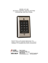
! 3x4 Keypad (left) and
2x6 Keypad (right)
The Essex SKE Series 12-Pad Self-
Contained Keyless Entry® System With
Relay is an extremely versatile Keypad
that can be configured in the field. The
500-user code system consists of either a
3x4 or 2x6 Keypad.
Input Voltage: 5VDC or 12 to 24VDC (Jumper
Selectable)
Standby Current Draw: 25mA
Outputs: 1 Relay, 2A Max; 2 Open Collector,
1/4 A Max to Ground
Keypad Switch Life: >1 Billion Cycles
Keypad Operating Environment: -40°C to +70°C (-40°F to +160°F),
100% Relative Humidity
3x4 Keypad Dimensions: 5-1/8"H x 3-3/8"W x 7/16"D
(13 x 8.6 x 1.1 cm)
2x6 Keypad Dimensions: 7-1/8"H x 1-3/4"W x 3/4"D
(13 x 8.6 x 1.1 cm)
3x4 Keypad Weight: 16 oz (454 gm)
2x6 Keypad Weight: 4.4 oz (125 gm)
LED's: 1 Red, 1 Green
Keypad
!!
!!
! Keypad Specifications

Essex Electronics, Inc. | 805.684.7601 | 800.KEY-LESS | fax 805.684.0232 | keyless.com
2
!!
!!
! Keypad Part Numbers
3x4 Keypad
SKE-34B Brass Finished* Bezel
SKE-34S Stainless Steel Bezel
SKE-34K Black Bezel
SKE-34X No Bezel
2x6 Keypad
SKE-26B Brass Overlay
SKE-26I Illuminated
SKE-26S Stainless Steel Overlay
SKE-26R Braille Overlay
*Bezel is brass in appearance. Actual bezel is PVD-coated stainless
steel.

3
Essex Electronics, Inc. | 805.684.7601 | 800.KEY-LESS | fax 805.684.0232 | keyless.com
Keypad Connector Diagram
BLACK- Ground
YELLOW- Anti Tailgate
If not used, this must be connected to BLACK. By adding a door
monitor switch between YELLOW and BLACK, the door will relock
immediately after opening. If the third output is set up as an
Internal Alarm, this switch will trigger the alarm if the door is
opened without a code or if the door is left open longer than the
Door Ajar Time setting.
CONFIGURATION
PINS- “CONFIG”
VOLTAGE SELECT
(Do NOT apply voltage)
12-24V (default)- Jumper on
1 pin only
5V- Jumper on both pins
YELLOW- Anti
Tailgate/Internal Alarm
(Do NOT apply voltage)
PINK- Remote Bypass
(Do NOT apply voltage)
BLUE- Common
BROWN- 24-hr Access (Do
NOT apply voltage)
TAN- Earth Ground
BLACK- Ground
ORANGE- Program (Do NOT
apply voltage)
VIOLET- Normally Open
RED- Input Voltage
WHITE- Output A
GREEN- Output B
NOTE: The 2x6 connector is rotated 180 degrees
GRAY- Normally Closed

Essex Electronics, Inc. | 805.684.7601 | 800.KEY-LESS | fax 805.684.0232 | keyless.com
4
PINK- Remote Bypass
Connect a Normally Open push button between PINK and BLACK
to trigger the main output for its normal Door Open Time setting.
ORANGE- Set Up Programming
Momentarily connecting ORANGE to BLACK puts the unit in Set
Up Mode (same as entering * 3, Master Code #).
BROWN- 24-hour Access
If Time Clock is enabled in Set up (page 16) and the BROWN wire
is grounded, all codes work normally. When the BROWN wire is
not grounded, only those codes with 24-hour Access Authorization
(page 17) will function.
Internal Relay Wiring Diagram
Note: A and B Keypad outputs are transistor outputs intended to
drive an external relay.

5
Essex Electronics, Inc. | 805.684.7601 | 800.KEY-LESS | fax 805.684.0232 | keyless.com
Keypad Configuration
Voltage Selection
The factory default setting for the Keypad voltage is 12-24VDC.
Verify that the jumper is removed or placed over only one pin. For
5VDC, the jumper should be placed across both pins. If changing
the voltage is necessary, make sure the power is removed first.
Keypad Output Selection
Once the voltage jumper is verified or correctly set (see above):
1. Remove power.
2. Jumper the two pins above the connector labeled "CONFIG.”
3. Apply appropriate power. (You should hear 4 beeps and the
RED LED will flash and the GREEN LED will be solid).
4. Now that the Keypad is in configuration mode, select the
desired output by entering the configuration number followed
by #.
a. Keypad Output
Keypad Output Configuration
Self-Contained- Non-encoded 99 #
b. To change the audible beep, enter
Code Audible Beep
201 # Normal Beep (factory default)
200 # Short Click (quieter)

Essex Electronics, Inc. | 805.684.7601 | 800.KEY-LESS | fax 805.684.0232 | keyless.com
6
c. To change the illumination on the SKE-26 only, enter the
code as follows:
Code Standby Mode Normal Operation
210 # Off (factory default) Off (factory default)
211 # Off Dim
212 # Off Bright
213 # Dim Dim
214 # Dim Bright
You should hear 3 beeps indicating successful configuration
(the RED LED will continue to flash and the GREEN LED will
be solid). If you hear a long error beep, re-enter the configura-
tion number followed by #.
5. Remove power.
6. Remove configuration jumper.
7. Re-apply power.
IMPORTANT: Once the configuration is selected, you must re-
move power, remove the configuration jumper and then re-apply
power in order to complete the configuration procedure. Note: If
the configuration jumper is not removed, the LED's will flash and
the Keypad will beep continuously.
Keypad Reset
In certain cases you may want to erase all user codes and restore
system defaults. To perform this procedure:

7
Essex Electronics, Inc. | 805.684.7601 | 800.KEY-LESS | fax 805.684.0232 | keyless.com
CAUTION: This procedure completely erases the memory and
restores factory defaults!!! Once the memory is cleared, all pro-
grammed User Codes are erased and factory default settings
are restored.
1. Remove power.
2. Jumper the two pins above the connector labeled "CONFIG.”
3. Apply appropriate power. (You should hear 4 beeps and the
RED LED will flash and the GREEN LED will be solid).
4. Once the Keypad is in configuration mode, enter 0099#. The
Keypad will beep twice and both LEDs will flash for approxi-
mately 10 seconds. (During this time, the Keypad will appear
dead. Do NOT remove power!!!)
5. Once the reset is complete, you will hear 4 beeps and the
RED LED will flash and the GREEN LED will be solid.
6. Enter the configuration number followed by #.
a. Keypad Output
Keypad Output Configuration
Self-Contained - Non-encoded 99 #
b. To change the audible beep, enter
Code Audible Beep
201 # Normal Beep (factory default)
200 # Short Click (quieter)

Essex Electronics, Inc. | 805.684.7601 | 800.KEY-LESS | fax 805.684.0232 | keyless.com
8
c. To change the illumination on the SKE-26 only, enter the
code as follows:
Code Standby Mode Normal Operation
210 # Off (factory default) Off (factory default)
211 # Off Dim
212 # Off Bright
213 # Dim Dim
214 # Dim Bright
You should hear 3 beeps indicating successful configuration
(the RED LED will continue to flash and the GREEN LED will
be solid). If you hear a long error beep, re-enter the configura-
tion number followed by #.
7. Remove power.
8. Remove configuration jumper.
9. Re-apply power.

9
Essex Electronics, Inc. | 805.684.7601 | 800.KEY-LESS | fax 805.684.0232 | keyless.com
Self-Contained Keyless Entry®
System With Relay
!!
!!
! Specifications
Input Voltage: 5VDC or 12 to 24VDC (Jumper
Selectable)
Standby Current Draw: 25mA
Outputs: 1 Relay, 2A 24V Max; 2 Open
Collector, 1/4 A Max to Ground
Programmable Output: 1 to 99 seconds
(Door Open Time) Default - 5 seconds
Latching: Off (Default), Manual (Toggle On/Off)
Timed
# of Users: 502 (1 Master User, 500 Users,
1 Temporary User
Code Length: 3 to 8 Digits
Default Master Code: 1-2-3
Tamper Alarm: 4 Incorrect Code Attempts
Access Code Protection: Non-Volatile Memory

Essex Electronics, Inc. | 805.684.7601 | 800.KEY-LESS | fax 805.684.0232 | keyless.com
10
!!
!!
! Configuration
Input Requirements
The SKE Series accepts 5VDC or 12 - 24VDC. System current
draw (max) is as follows:
! Standby: 25mA
! During Operation: 100mA
Output Capabilities
Main Door Output
SPDT relay rated at 24V 2A Max.
Output A
A transistor output intended to drive a relay that can be pro-
grammed for one of the following:
1. CCTV or Light Controller - First key press triggers a Timed
Output (1 to 99 seconds).
2. Auxiliary Output - Manual Control or Timed Output (1 to 99
seconds).
3. Second Door - Users can be assigned to open a 2nd door.
4. Doorbell - Press # at the Keypad to trigger a 1 second output
for a doorbell (not included).
Output B
A transistor output intended to drive a relay that can be pro-
grammed for one of the following:
1. CCTV or Light Controller - First key press triggers a Timed
Output (1 to 99 seconds).
2. Auxiliary Output - Manual Control or Timed Output (1 to 99
seconds).

11
Essex Electronics, Inc. | 805.684.7601 | 800.KEY-LESS | fax 805.684.0232 | keyless.com
3. Third Door - Users can be assigned to open a 3rd door.
4. Internal Alarm System - Detect Break-in, Door-ajar & Tamper.
5. Doorbell - Press # at the Keypad to trigger a 1 second output
for a doorbell (not included).

Essex Electronics, Inc. | 805.684.7601 | 800.KEY-LESS | fax 805.684.0232 | keyless.com
12
Programming System Setup
The System Setup can only be modified if you know the Master Code.
When the system is initially set up, the default system settings should be
reviewed
prior to other programming.
1. Enter * 3
2. Enter the Master Code followed by #
Example: * 3 1 2 3 #
This opens programming and causes:
3. Proceed to one of the following eight programming options:
! Changing the Master Code (Default: 1,2,3)
a. Enter 1 #
b. Enter the New Master Code followed by #
c. Return to Step 3 or enter * * to exit programming.
Keypad Status After Step Completion
Step Beep Red LED Green LED
a Double Fast Flash Slow Flash
b Triple Fast Flash Solid
Note: If you forget the Master Code, momentarily ground the
ORANGE wire. This will take you to Step 3 of Programming System
Setup. Once you enter setup mode, you have 30 seconds to begin the
program sequence.
Red LED Green LED
Fast Flash Solid

13
Essex Electronics, Inc. | 805.684.7601 | 800.KEY-LESS | fax 805.684.0232 | keyless.com
! Setting the Main Door Open Time (Default: 5 Seconds)
a. Enter 2 #
b. Enter the desired Door Open Time (1-99 seconds), followed by #
Example: 2 # 1 5 # (15 sec. Door Open Time)
c. Return to Step 3 or enter * * to exit programming.
Keypad Status After Step Completion
Step Beep Red LED Green LED
a Double Slow Flash Slow Flash
b Triple Slow Flash Solid
! Setting Latching Option (Default: Off)
a. Enter 3 #
b. Select the desired latching option:
Off- 0 #
Manual- 9 9 #
Timed- Enter the desired time interval in hours (1-98), followed
by #.
Example: 3 # 8 # (Sets timed latching for 8 hrs)
c. Return to Step 3 or enter * * to exit programming.
Keypad Status After Step Completion
Step Beep Red LED Green LED
a Double Slow Flash Slow Flash
b Triple Slow Flash Solid
! Configuring Output A (Default: Aux #1)
a. Enter 4 #
b. Select one of the following:
! CCTV / External Light
1) Enter 1 #

Essex Electronics, Inc. | 805.684.7601 | 800.KEY-LESS | fax 805.684.0232 | keyless.com
14
2) Enter the desired On Time (1-99 seconds), followed by #
Example: 4 # 1 # 1 5 #
(Sets CCTV/Light Option for 15 seconds)
! Auxiliary Device #1
1) Enter 2 #
2) Enter the momentary output time (1-99 seconds), followed by
# ; -or- Enter 0 to set the auxiliary device for Manual
Operation (ON/OFF), followed by #
Example: 4 # 2 # 0 #
(Sets Auxiliary Device with Manual Operation)
! Second Door
1) Enter 3 #
2) Enter the desired Door Open Time (1-99 seconds), followed
by #
3) Select the desired latching method:
Off- 0 #
Manual- 9 9 #
Timed- Enter the desired time interval in hours (1-98),
followed by #
Example: 4 # 3 # 5 # 9 9 #
(Sets Second Door with 5 second Door Open Time and
Manual Latching)
! Doorbell
1) Enter 4 #
c. Return to Step 3 or enter * * to exit programming.
Keypad Status After Step Completion
Step Beep Red LED Green LED
a Double Slow Flash Slow Flash
1) Double Slow Flash Fast Flash
2) Triple Slow Flash Solid

15
Essex Electronics, Inc. | 805.684.7601 | 800.KEY-LESS | fax 805.684.0232 | keyless.com
! Configuring Output B (Default: CCTV)
a. Enter 5 #
b. Select one of the following:
! CCTV / External Light
1) Enter 1 #
2) Enter the desired On Time (1-99 seconds), followed by #
Example: 5 # 1 # 1 5 #
(Sets CCTV/Light Option for 15 seconds)
! Auxiliary Device #2
1) Enter 2 #
2) Enter the momentary output time (1-99 seconds), followed by
#; -or- Enter 0 to set the auxiliary device for Manual
Operation (ON/OFF), followed by #
Example: 5 # 2 # 0 #
(Sets Auxiliary Device with Manual Operation)
! Third Door
1) Enter 3 #
2) Enter the desired Door Open Time (1-99 seconds), followed
by #
3) Select the desired latching method:
Off- 0 #
Manual- 9 9 #
Timed- Enter the desired time interval in hours (1-98),
followed by #
Example: 5 # 3 # 5 # 9 9 #
(Sets Second Door with 5 second Door Open Time and
Manual Latching)
! Doorbell
1) Enter 4 #

Essex Electronics, Inc. | 805.684.7601 | 800.KEY-LESS | fax 805.684.0232 | keyless.com
16
!
Internal Alarm
1) Enter 5 #
2) Enter the desired Door Ajar Time (1-99 seconds), followed
by #
Example: 5 # 5 # 1 0 #
(Sets Internal Door with 10 second Door Ajar Time)
! Master Code Door Unlock Option (Default: Allow)
a. Enter 6 #
b. Enter 0 # to prevent the master code from unlocking the door.
c. Enter 1 # to allow the master code to unlock the door.
d. Return to Step 3 or enter * * to exit programming.
! Time Clock Input (Default: Prevent)
a. Enter 7 #
b. Enter 0 # to prevent lockout
c. Enter 1 # to lockout all users that do not have 24 hour option
enabled.
d. Return to Step 3 or enter * * to exit programming.
4. Enter * * to complete the sequence and reset the system to normal
operation.
/