
Publication 1764-5.1
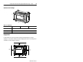
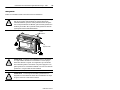
MicroLogix™ 1500 Programmable
Controller Base Units
(Catalog Numbers 1764-24AWA, 1764-24BWA,
and 1764-28BXB)
Installation Instructions
Inside...
English Section........................................................................... 3
Français.................................................................................... 19
Deutscher Abschnitt.................................................................. 35
Sezione in Italiano..................................................................... 51
Sección en español................................................................... 67
Seção em Português ................................................................ 83

2
MicroLogix™ 1500 Programmable Controller Base Units
Publication 1764-5.1

Publication 1764-5.1
English Section
MicroLogix™ 1500 Programmable
Controller Base Units
(Catalog Numbers 1764-24AWA, 1764-24BWA,
and 1764-28BXB)
Installation Instructions
Inside...
For More Information .................................................................. 4
Overview..................................................................................... 5
Base Unit Description................................................................. 6
Hazardous Location Considerations........................................... 7
Mounting the Controller............................................................... 8
Wiring the Controller................................................................. 13
Specifications............................................................................ 16

4
MicroLogix™ 1500 Programmable Controller Base Units
Publication 1764-5.1
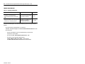
For More Information
If you would like a manual, you can:
• download a free electronic version from the internet:
www.ab.com/micrologix
or
www.theautomationbookstore.com
• purchase a printed manual by:
– contacting your local distributor or Rockwell Automation representative
– visiting
www.theautomationbookstore.com
and placing your order
– calling
1.800.9NEWLIT(800.963.9548)
(USA/Canada)
or
001.330.725.1574
(Outside USA/Canada)
Table 1: Related Publications
For Refer to this Document Pub. No.
A more detailed description of how to install
and use your MicroLogix 1500 programmable
controller.
MicroLogix 1500 Programmable
Controllers User Manual
1764-6.1
More information on proper wiring and
grounding techniques.
Industrial Automation Wiring
and Grounding Guidelines
1770-4.1

MicroLogix™ 1500 Programmable Controller Base Units
5
Publication 1764-5.1
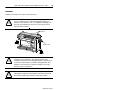
Overview
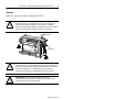
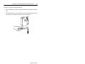
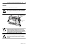
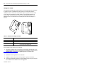
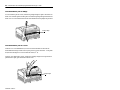
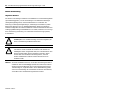
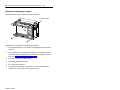
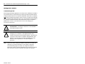
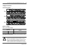
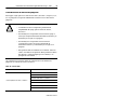
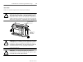
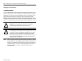
Install your controller using these installation instructions.
!
ATTENTION:
Do not remove protective debris strips until after
the base and all other equipment in the panel near the base is
mounted and wiring is complete. Once wiring is complete,
remove protective debris strips and install processor unit. Failure
to remove strips before operating can cause overheating.
!
ATTENTION:
Be careful of metal chips when drilling
mounting holes for your controller or other equipment within the
enclosure or panel. Drilled fragments that fall into the controller
could cause damage. Do not drill holes above a mounted
controller if the protective debris strips have been removed.
!
ATTENTION:
Electrostatic discharge can damage
semiconductor devices inside the base unit. Do not touch the
connector pins or other sensitive areas.
Protective
Debris Strips
ESD Sticker

6
MicroLogix™ 1500 Programmable Controller Base Units
Publication 1764-5.1
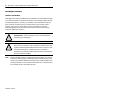
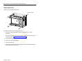
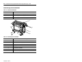
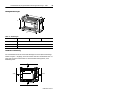
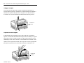
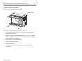
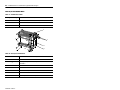
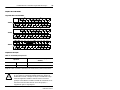
Base Unit Description
Table 2: Standard Base Units
Catalog Number Base Unit I/O and Power Supply
1764-24AWA 120V ac inputs/ relay outputs/ 120/240V ac power supply
1764-24BWA 24V dc inputs/ relay outputs/ 120/240V ac power supply
1764-28BXB 24V dc inputs/ FET and relay outputs/ 24V dc power supply
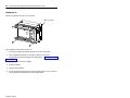
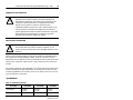
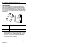
Table 3: Base Unit Description
Feature Description
1 Removable Terminal Blocks
2 Interface to Expansion I/O, Removable ESD Sticker
3 Input LEDs
4 Output LEDs
5 Communication Port
6 Status LEDs
7 Terminal Doors and Label
2
3
4
5
6
7
1
1

MicroLogix™ 1500 Programmable Controller Base Units
7
Publication 1764-5.1
Hazardous Location Considerations
This equipment is suitable for use in Class I, Division 2, Groups A, B, C, D or
non-hazardous locations only. The following ATTENTION statement applies to
use in hazardous locations.
Use only the following communication cables in Class I, Division 2 hazardous
locations.
!
ATTENTION:
EXPLOSION HAZARD
• Substitution of components may impair suitability for Class
I, Division 2.
• Do not replace components or disconnect equipment unless
power has been switched off or the area is known to be non-
hazardous.
• Do not connect or disconnect components unless power has
been switched off or the area is known to be non-hazardous.
• This product must be installed in an enclosure. All cables
connected to the product must remain in the enclosure or be
protected by conduit or other means.
Table 4: Cable Listing
Environment Classification Communication Cables
Class I, Division 2 Hazardous Environment 1761-CBL-PM02 Series C or later
1761-CBL-HM02 Series C or later
1761-CBL-AM00 Series C or later
1761-CBL-AP00 Series C or later
2707-NC8 Series B or later
2707-NC10 Series B or later
2707-NC11 Series B or later

8
MicroLogix™ 1500 Programmable Controller Base Units
Publication 1764-5.1
Mounting the Controller
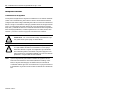
General Considerations
Most applications require installation in an industrial enclosure (Pollution Degree
2) to reduce the effects of electrical interference (Over Voltage Category II) and
environmental exposure. Locate your controller as far as possible from power
lines, load lines, and other sources of electrical noise such as hard-contact
switches, relays, and AC motor drives. For more information on proper
grounding guidelines, see the
Industrial Automation Wiring and Grounding
Guidelines
publication 1770-4.1.
Note:
Remove the ESD sticker to install expansion I/O modules. An end cap
terminator (catalog number 1769-ECR) must be used at the end of the
group of I/O modules attached to the MicroLogix 1500 Controller. The
end cap terminator is not provided with the base unit. A maximum of 8
I/O modules may be connected to the base.
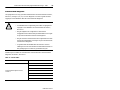
!
ATTENTION:
Vertical mounting is not recommended due to
heat build-up considerations.
!
ATTENTION:
Be careful of metal chips when drilling mounting
holes for your controller or other equipment within the enclosure
or panel. Drilled fragments that fall into the base or processor unit
could cause damage. Do not drill holes above a mounted
controller if the protective debris strips have been removed or the
processor has been installed.

MicroLogix™ 1500 Programmable Controller Base Units
9
Publication 1764-5.1
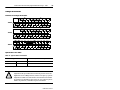
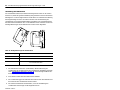
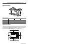
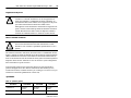
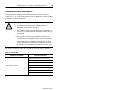
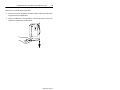
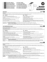
Mounting Dimensions
Controller Spacing
The base unit is designed to be mounted horizontally, with the Compact™
expansion I/O extending to the right of the base unit. Allow 50 mm (2 in.) of
space on all sides for adequate ventilation, as shown below.
Table 5: Dimensions
Dimension 1764-24AWA 1764-24BWA 1764-28BXB
Height (A) 138 mm (5.43 in.)
Width (B) 168 mm (6.62 in.)
Depth (C) 87 mm (3.43 in.)
A
C
B
Top
Bottom
Side
Side

10
MicroLogix™ 1500 Programmable Controller Base Units
Publication 1764-5.1
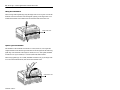
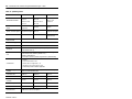
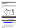
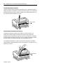
Using a DIN Rail
The base unit and expansion I/O DIN rail latches lock in the open position so that
an entire system can be easily attached to or removed from the DIN rail. The
maximum extension of the latch is 15 mm (0.67 in.) in the open position. A flat-
blade screw driver is required for removal of the base unit. The base can be
mounted to EN50022-35x7.5 or EN50022-35x15 DIN rails. DIN rail mounting
dimensions are shown below.
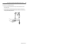
To install your base unit on the DIN rail:
1. Mount your DIN rail. (Make sure that the placement of the base unit on the
DIN rail meets the recommended spacing requirements, see “Controller
Spacing” on page 9. Refer to the mounting template from the inside back
cover of this document.)
2. Hook the top slot over the DIN rail.
3. While pressing the base unit down against the top of the rail, snap the
bottom of the base unit into position.
4. Leave the protective debris strip attached until you are finished wiring the
base unit and any other devices.
Table 6: DIN Rail Mounting Dimensions
Dimension Height
A 138 mm (5.43 in.)
B 47.6 mm (1.875 in.)
C
47.6 mm (1.875 in) DIN latch closed
54.7 mm (2.16 in.) DIN latch open
B
C
A

MicroLogix™ 1500 Programmable Controller Base Units
11
Publication 1764-5.1
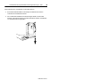
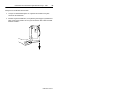
To remove your base unit from the DIN rail:
1. Place a flat-blade screwdriver in the DIN rail latch at the bottom of the base
unit.
2. Holding the base unit, pry downward on the latch until the latch locks in the
open position. This releases the base unit from the DIN rail.

12
MicroLogix™ 1500 Programmable Controller Base Units
Publication 1764-5.1
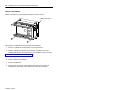
Using Mounting Screws
Mount to panel using #8 or M4 screws.
To install your base unit using mounting screws:
1. Remove the mounting template from the inside back cover of this
document.
2. Secure the template to the mounting surface. (Make sure your base unit is
spaced properly, see “Controller Spacing” on page 9).
3. Drill holes through the template.
4. Remove the mounting template.
5. Mount the base unit.
6. Leave the protective debris strips attached until you are finished wiring the
base unit and any other devices.
Mounting Template

MicroLogix™ 1500 Programmable Controller Base Units
13
Publication 1764-5.1
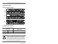
Wiring the Controller
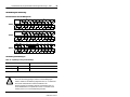
Terminal Block Layout
Wire Requirements
Wiring torque = 0.678 Nm to 0.904 Nm (6 in-lb to 8 in-lb) rated; 1.3 Nm (12 in-lb) maximum
.
Table 7: Wire Type Recommendation
Wire Type Wire Size (2 wire maximum per terminal screw)
Solid Cu-90°C (194°F) #14 to #22 AWG
Stranded Cu-90°C (194°F) #14 to #22 AWG
!
ATTENTION:
Be careful when stripping wires. Wire fragments
that fall into the controller could cause damage. Once wiring is
complete, be sure the base unit is free of all metal fragments
before removing protective debris strips and installing the
processor unit. Failure to remove strips before operating can
cause overheating.
24AWA
28BXB
24BWA
+24V
DC
COM 0
I / 1
I / 0
I / 3
I / 2
I / 4
DC
COM 1
I / 6
I / 5
DC
COM 2
I / 7
I / 9
I / 8
I / 11
I / 10
DC
POWER
OUT
24BWA
COM
VAC
VDC 0
85-265
VAC
O / 5
VAC
VDC 1
VAC
VDC 2
VAC
VDC 4
O / 7 O / 8
O / 10
O / 4O / 1O / 0 L1 O / 2 O / 6 O / 9 O / 11
VAC
VDC 5
24BWA
VAC
VDC 3
O / 3
L2
I / 4 I / 6
I / 5
I / 9
I / 8 I / 10
I / 15
28BXB
NOT
USED
NOT
USED
DC
COM 0
I / 0
I / 1 I / 3
I / 2
DC
COM 1
I / 7
DC
COM 2
I / 12 I / 14
I / 13I / 11
24 VDC
O / 7
VAC
VDC 0
COM
VAC
VDC 1
VAC
VDC 3
O / 9 O / 10
O / 6O / 1O / 0+24V O / 2 O / 11
28BXB
O / 4
VDC 2 O / 5O / 3
VDC
COM 2
O / 8
VAC
VDC 4
AC
COM 0
I / 1
I / 0
I / 3
I / 2
I / 4
AC
COM 1
I / 6
I / 5
AC
COM 2
I / 7
I / 9
I / 8
I / 11
I / 10
24AWA
NOT
USED
NOT
USED
85-265
VAC
O / 5
VAC
VDC 0
L2
VAC
VDC 1
VAC
VDC 2
VAC
VDC 4
O / 7 O / 8 O / 10
O / 4
O / 1
O / 0L1 O / 2 O / 6 O / 9 O / 11
VAC
VDC 5
24AWA
VAC
VDC 3
O / 3

14
MicroLogix™ 1500 Programmable Controller Base Units
Publication 1764-5.1
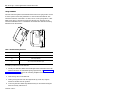
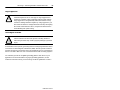
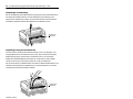
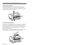
Wiring Recommendation
When wiring without spade lugs, keep the finger-safe covers in place. Loosen the
terminal screw and route the wires through the opening in the finger-safe cover.
Tighten the terminal screw making sure the pressure plate secures the wire.
Spade Lug Recommendation
The diameter of the terminal screw head is 5.5 mm (0.220 in.). The input and
output terminals of the MicroLogix 1500 base unit are designed for the following
spade lugs. The terminals will accept a 6.35mm (0.25 in.) wide spade (standard
for #6 screw for up to 14 AWG) or a 4 mm (metric #4) fork terminal.
When using spade lugs, use a small, flat-blade screwdriver to pry the finger-safe
cover from the terminal blocks, then loosen the terminal screw.
Finger-Safe Cover
Finger-Safe Cover

MicroLogix™ 1500 Programmable Controller Base Units
15
Publication 1764-5.1
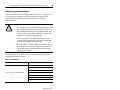
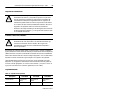
Surge Suppression
Grounding the Controller
In solid-state control systems, grounding and wire routing helps limit the effects
of noise due to electromagnetic interference (EMI). Run the ground connection
from the ground screw of the base unit to the ground bus prior to connecting any
devices. Use AWG #14 wire. This connection must be made for safety purposes.
You must also provide an acceptable grounding path for each device in your
application. For more information on proper grounding guidelines, see the
Industrial Automation Wiring and Grounding Guidelines
publication 1770-4.1.
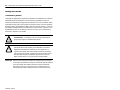
!
ATTENTION:
Inductive load devices such as motor starters and
solenoids require the use of some type of surge suppression to
protect the controller output. Switching inductive loads without
surge suppression can significantly reduce the lifetime of relay
contacts or damage transistor outputs. By using suppression, you
also reduce the effects of voltage transients caused by interrupting
the current to that inductive device, and prevent electrical noise
from radiating into system wiring.
!
ATTENTION:
All devices connected to the RS-232 channel
must be referenced to base unit ground or floating. Failure to
follow this procedure may result in property damage or personal
injury.

16
MicroLogix™ 1500 Programmable Controller Base Units
Publication 1764-5.1
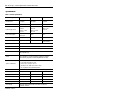
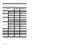
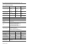
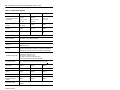
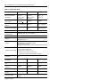
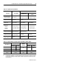
Specifications
Table 8: General Specifications
Description 1764-24BWA 1764-24AWA 1764-28BXB
Number of I/O
12 inputs
12 outputs
12 inputs
12 outputs
16 inputs
12 outputs
Line Power 85/265V ac 85/265V ac 20.4 to 30V dc
Power Supply Inrush
120V ac = 25 A
for 8 ms
240V ac = 40 A
for 4 ms
120V ac = 25 A
for 8 ms
240V ac = 40 A
for 4 ms
24V dc = 4 A
for 150 ms
User Power Output
24V dc at 400 mA,
400 µf max.
none none
Input Circuit Type 24V dc, sink/source 120V ac 24V dc, sink/source
Output Circuit Type relay relay
6 relay,
6 FET transistor
Operating Temp. +0°C to +55°C (+32°F to +131°F) ambient
Storage Temp. -40°C to +85°C (-40°F to +185°F) ambient
Operating Humidity 5% to 95% relative humidity (non-condensing)
Vibration
Operating: 10 to 500 Hz, 5g, 0.015 in. peak-to-peak
Relay Operation: 2g
Shock
Operating: 30g panel mounted (20g DIN Rail mounted)
Relay Operation: 7.5g panel mounted (5 g DIN Rail mounted)
Non-Operating: 40g panel mounted (30g DIN Rail mounted)
Agency Certification
• UL 508
• C-UL under CSA C22.2 no. 142
• Class I, Div. 2, Groups A, B, C, D
(UL 1604, C-UL under CSA C22.2 no. 213)
• CE compliant for all applicable directives
Terminal Screw Torque 0.678 Nm to 0.904 Nm (6 in-lb to 8 in-lb) rated; 1.3 Nm (12 in-lb) max.
Power Supply Isolation 2596V dc 2596V dc 1697V dc
Relay Outputs Isolation 2596V dc 2596V dc 2596V dc
Transistor Output Isolation none none 1697V dc
Inputs Isolation 2145V dc 2145V dc 1697V dc
User 24V Isolation 848V dc none none
User Manual
MicroLogix 1500 Programmable Controllers User Manual,
publication 1764-6.1

MicroLogix™ 1500 Programmable Controller Base Units
17
Publication 1764-5.1
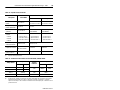
➀
Scan-time dependant.
➁
For dc voltage applications, the make/break ampere rating for relay contacts can be determined by
dividing 28 VA by the applied dc voltage. For example, 28 VA/48V dc = 0.58A. For dc voltage
applications less than 48V, the make/break ratings for relay contacts cannot exceed 2A.
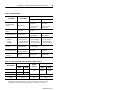
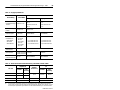
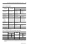
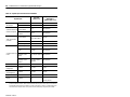
Table 9: Input Specifications
Description 1764-24AWA
1764-24BWA and 1764-28BXB
Inputs 0 thru 7 Inputs 8 and Higher
On State Voltage
Range
79 to 132V ac
14 to 30.0 V dc at
30°C (86°F)
14 to 26.4 V dc at
55°C (131°F)
10 to 30.0 V dc at
30°C (86°F)
10 to 26.4 V dc at
55°C (131°F)
Off State Voltage
Range
0 to 20V ac 0 to 5V dc
Operating Frequency 47 Hz to 63 Hz
0 Hz to 20 KHz
(1764-24BWA)
0 Hz to 1 KHz
➀
(1764-24BWA)
On State Current:
•minimum
• nominal
• maximum
• 5.0 mA at 79V ac
• 12.0 mA at 120V ac
• 16.0 mA at 132V ac
• 2.5 mA at 14V dc
• 8.8 mA at 24V dc
• 12.0 mA at 30V dc
• 2.0 mA at 10V dc
• 8.5 mA at 24V dc
• 12.0 mA at 30V dc
Off State Leakage
Current
2.5 mA minimum 1.5 mA minimum
Nominal Impedance
12k ohms at 50 Hz
10k ohms at 60 Hz
2.5k ohms 2.6k ohms
Inrush Current (max.)
at 120V ac
250 mA Not Applicable Not Applicable
Table 10: Relay Contact Rating Table 1764-24AWA, -24BWA, -28BXB
Maximum Volts
Amperes
Amperes
Continuous
Voltamperes
Make Break Make Break
240V ac 7.5A 0.75A
2.5A 1800VA 180VA
120V ac 15A 1.5A
125V dc 0.22A
➁
1.0A 28VA
24V dc 1.2A
➁
2.0A 28VA

18
MicroLogix™ 1500 Programmable Controller Base Units
Publication 1764-5.1
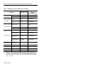
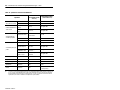
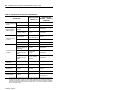
➀
Outputs 2 and 3 are designed to provide increased functionality over the other FET outputs (4 through 7).
They may be used like the other FET transistor outputs, but in addition, within a limited current range,
they may be operated at a higher speed. Outputs 2 and 3 also provide a pulse train output (PTO) or
pulse width modulation output (PWM) function.
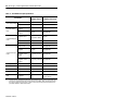
Table 11: 1764-28BXB FET Output Specifications
Specification
General Operation
(Outputs 2 thru 7)
High Speed Operation
➀
(Outputs 2 and 3 Only)
User Supply Voltage
minimum 20.4V dc 20.4V dc
maximum 26.4V dc 26.4V dc
On-State Voltage
Drop
at maximum load
current
1V dc Not Applicable
at maximum surge
current
2.5V dc Not Applicable
Current Rating per
Point
maximum load
1A at 55°C (131°F)
1.5A at 30°C (86°F)
100 mA
minimum load 1.0 mA 10 mA
maximum leakage 1.0 mA 1.0 mA
Surge Current per
Point
peak current 4.0A Not Applicable
maximum surge
duration
10 msec Not Applicable
maximum rate of
repetition at 30°C
(86°F)
once every second Not Applicable
maximum rate of
repetition at 55°C
(131°F)
once every 2 seconds Not Applicable
Current per Common maximum total 6A 6A
Turn-On Time maximum 0.1 msec 6 µsec
Turn-Off Time maximum 1.0 msec 18 µsec
Repeatability maximum n/a 2 µsec
Drift maximum n/a
1 µsec per 5°C
(1 µsec per 9°F)
Page is loading ...
Page is loading ...
Page is loading ...
Page is loading ...
Page is loading ...
Page is loading ...
Page is loading ...
Page is loading ...
Page is loading ...
Page is loading ...
Page is loading ...
Page is loading ...
Page is loading ...
Page is loading ...
Page is loading ...
Page is loading ...
Page is loading ...
Page is loading ...
Page is loading ...
Page is loading ...
Page is loading ...
Page is loading ...
Page is loading ...
Page is loading ...
Page is loading ...
Page is loading ...
Page is loading ...
Page is loading ...
Page is loading ...
Page is loading ...
Page is loading ...
Page is loading ...
Page is loading ...
Page is loading ...
Page is loading ...
Page is loading ...
Page is loading ...
Page is loading ...
Page is loading ...
Page is loading ...
Page is loading ...
Page is loading ...
Page is loading ...
Page is loading ...
Page is loading ...
Page is loading ...
Page is loading ...
Page is loading ...
Page is loading ...
Page is loading ...
Page is loading ...
Page is loading ...
Page is loading ...
Page is loading ...
Page is loading ...
Page is loading ...
Page is loading ...
Page is loading ...
Page is loading ...
Page is loading ...
Page is loading ...
Page is loading ...
Page is loading ...
Page is loading ...
Page is loading ...
Page is loading ...
Page is loading ...
Page is loading ...
Page is loading ...
Page is loading ...
Page is loading ...
Page is loading ...
Page is loading ...
Page is loading ...
Page is loading ...
Page is loading ...
Page is loading ...
Page is loading ...
Page is loading ...
Page is loading ...

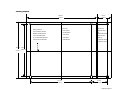
Publication 1764-5.1
Mounting Template
168 mm
(6.62 in.)
147 mm
(5.78 in.)
DIN rail center line.
Ligne médiane du rail DIN.
Mittellinie der DIN-Schiene.
Línea central del riel DIN.
Linea centrale della guida DIN
linha de centro do trilho DIN.
122 mm
(4.813 in.)
132 mm
(5.19 in.)
38 mm
(1.49 in.)
35 mm
(1.37 in.)
Base Unit
Unité de base
Grundeinheiten
Unità di base
Unidad Base
Unidades Base
Expansion I/O
d'extension d'E/S
E/A-
Erweiterungsmodule
l’espansione dei
moduli I/O
de expansión de E/S
de expansão de E/S

Publication 1764-5.1 - November 1998 40072-055-01(A)
1998 Rockwell International. All Rights Reserved. Printed in USA
´H'4W!¶AG¨
-
 1
1
-
 2
2
-
 3
3
-
 4
4
-
 5
5
-
 6
6
-
 7
7
-
 8
8
-
 9
9
-
 10
10
-
 11
11
-
 12
12
-
 13
13
-
 14
14
-
 15
15
-
 16
16
-
 17
17
-
 18
18
-
 19
19
-
 20
20
-
 21
21
-
 22
22
-
 23
23
-
 24
24
-
 25
25
-
 26
26
-
 27
27
-
 28
28
-
 29
29
-
 30
30
-
 31
31
-
 32
32
-
 33
33
-
 34
34
-
 35
35
-
 36
36
-
 37
37
-
 38
38
-
 39
39
-
 40
40
-
 41
41
-
 42
42
-
 43
43
-
 44
44
-
 45
45
-
 46
46
-
 47
47
-
 48
48
-
 49
49
-
 50
50
-
 51
51
-
 52
52
-
 53
53
-
 54
54
-
 55
55
-
 56
56
-
 57
57
-
 58
58
-
 59
59
-
 60
60
-
 61
61
-
 62
62
-
 63
63
-
 64
64
-
 65
65
-
 66
66
-
 67
67
-
 68
68
-
 69
69
-
 70
70
-
 71
71
-
 72
72
-
 73
73
-
 74
74
-
 75
75
-
 76
76
-
 77
77
-
 78
78
-
 79
79
-
 80
80
-
 81
81
-
 82
82
-
 83
83
-
 84
84
-
 85
85
-
 86
86
-
 87
87
-
 88
88
-
 89
89
-
 90
90
-
 91
91
-
 92
92
-
 93
93
-
 94
94
-
 95
95
-
 96
96
-
 97
97
-
 98
98
-
 99
99
-
 100
100


Allen-Bradley Allen-Bradley MicroLogix 1500 1764-24AWA Installation Instructions Manual
- Type
- Installation Instructions Manual
- This manual is also suitable for
Ask a question and I''ll find the answer in the document
Finding information in a document is now easier with AI
in other languages
- italiano: Allen-Bradley Allen-Bradley MicroLogix 1500 1764-24AWA
- français: Allen-Bradley Allen-Bradley MicroLogix 1500 1764-24AWA
- español: Allen-Bradley Allen-Bradley MicroLogix 1500 1764-24AWA
- Deutsch: Allen-Bradley Allen-Bradley MicroLogix 1500 1764-24AWA
- português: Allen-Bradley Allen-Bradley MicroLogix 1500 1764-24AWA
Related papers
-
Allen-Bradley micrologix 1500 Installation Instructions Manual
-
Miles Industries 1500IP User manual
-
-
-
-
-
-
-
-
Other documents
-
CnMemory Latch 16GB Specification
-
CAME 818XA-0051 Installation guide
-
Rockwell Automation 1764-24AWA Installation Instructions Manual
-
Rockwell Automation 1769-PA2 Specification
-
 Rockwell Automation Allen-Bradley 1606-XLE120F Installation guide
-
 Rockwell Automation 1606-XLS120E User manual
-
Rockwell Automation 1766-L32AWAA Installation Instructions Manual
-
Rockwell Automation 1761-L16BWA Installation Instructions Manual
-
 Rockwell Automation 40072-107-01 Installation Instructions Manual
-


