Page is loading ...

REFRIGERATION AND
AIR CONDITIONING
Data communication cabel
for ADAP-KOOL® refrigeration Controls
DANBUSS Data communication system
Installation Guide

2 Installation Guide RC0XA402 © Danfoss 07/2006 DANBUSS
System description ................................................................................................................................................................ 2
General information about data communication ...................................................................................................... 3
Summary of requirements .................................................................................................................................................. 3
Cable type ................................................................................................................................................................................. 3
Cable layout.............................................................................................................................................................................. 4
Number of controllers ..........................................................................................................................................................
5
Cable ends ................................................................................................................................................................................ 5
Control panel type AKA 21
.................................................................................................................................................. 6
Signal amplier type AKA 222 ........................................................................................................................................... 8
Terminals .................................................................................................................................................................................10
Address coding .....................................................................................................................................................................11
The individual units in the system are connected by a two-core cable. All data communication
between the units takes place through this cable.
The following information may for instance be transmitted via the cable:
- Setpoints and regulation parameters for all connected controllers. The information is sent from
control panel type AKA 21 or from a PC, if one has been connected.
- Display and collection of operating data from all the controllers.
To allow the system to distinguish between the connected units, each unit is assigned an address.
This address is set on the unit, and a max. 124 addressable units may be connected.
For every 25 units, or in systems with very long cable sections, an amplier type AKA 222 must be
mounted in the data communication cable. An amplier is not provided with an address code and is
not subject to the limitation of 124 units.
A system must be tted with a Gateway, if the following is required:
- PC connection
- separate printer connection
- modem (communication via telephone cable)
- hook-up of two separate data communication systems
Contents
System description

DANBUSS Installation Guide RC0XA402 © Danfoss 07/2006 3
General information about
data communication
A data communication comprises the dierent elements needed to carry out a transfer of data
between two units. There are both hardware and software elements. Hardware in the form of wires
and transmitting and receiving circuits, and software ensuring that the messages in question are sent
and received by the correct units.
When information has to be transmitted, the sender is allocated “time to speak” in the communication
cable. The information is transmitted, and the sender now waits for the receiver to answer that
“the information has been received and is understood”. Not until the sender receives a message of
acknowledgement will the information transaction in question be terminated.
If there are disturbances during the data transmission so that the information is not understood, the
sender will repeat the transmission. If the sender is not successful in delivering the information after
several attempts, the sender will give up trying and instead deliver an error message.
Experience has shown that the number of unsuccessful transmissions and error messages is
higher, the poorer the installation of the data communication cable. A description therefore
follows of a number of instructions and requirements that have to be complied with to obtain data
communication without problems.
To ensure that the data communication will take a satisfactory course, a list has been set up of
requirements made for the installation of the data communication system. The individual items are
explained in more detail in the following section.
Summary:
- Comply with the specications for the cable
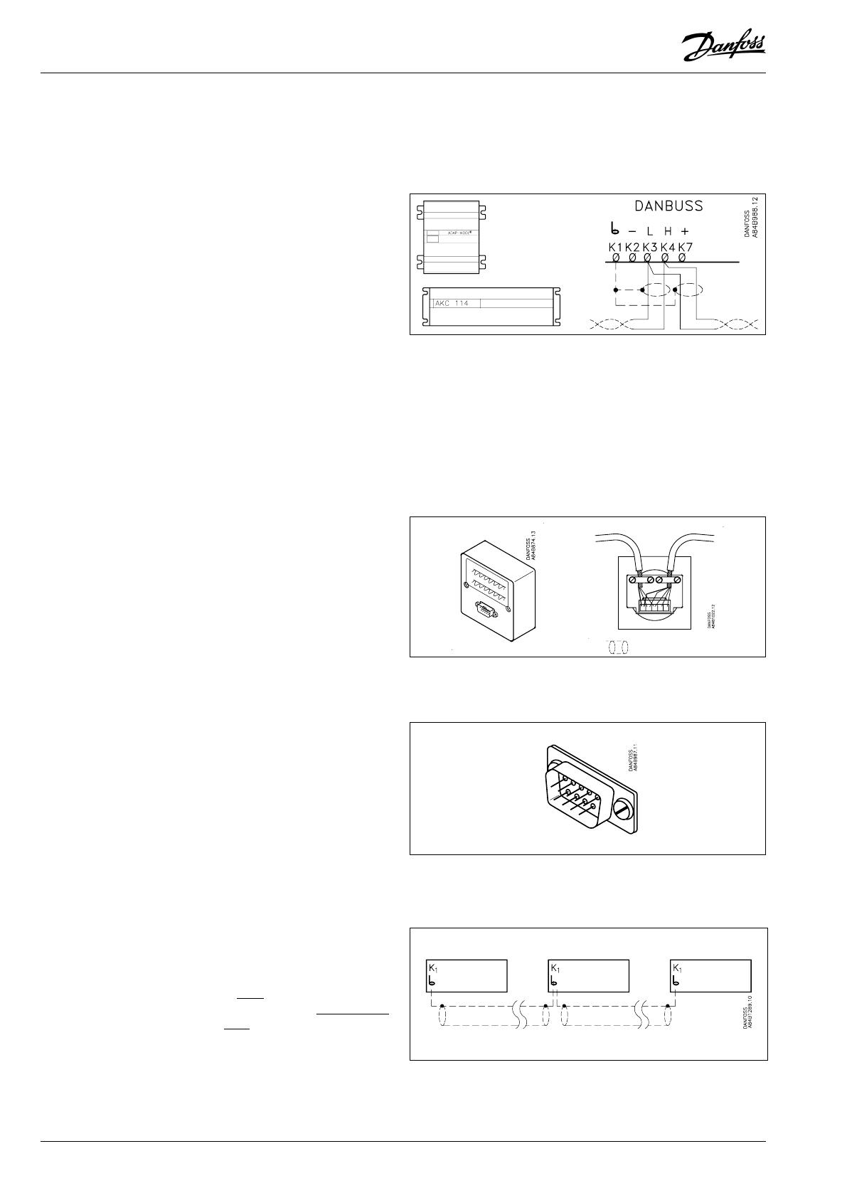
- Pair-twisted wires with screen must be used
- The screen must be connected at both ends, and the screen must touch nothing but
the “K1” terminals
- The two wires that are twisted must be used
- The wires are looped on from unit to unit. “L” is connected to “L”, and “H” is connected to “H”
- Keep the cable away from electric sources of noise
- If there are several “vacant” wires in the cable, they must exclusively be used for DANBUSS data
communication
- Avoid branch connections on the cable
- Perform a correct termination of the cable ends
The data communication cable must comply with the following specications:
- Pair-twisted wires
- 2 to 6 cm per twist
- Damping less than 8 dB per 1000 m at 100 kHz
- Moistureproof jacket if the cable is mounted in moist surroundings, e.g. concrete ducts,
or trenches
- It is recommended that the cable is screened
- The cable must be with screen
The following cable types comply with the specications:
NKT type SKPS 2 x 2 x 0.6 mm
Coferro type LiYCY 2 x 2 x 0.5 mm
Jydsk Kabel type PTS 2 x 2 x 0.6 mm
Moistureproof cable:
Coferro type RE-2Y(ST)Y 2 x 2 x 0.5 mm
The use of a cable with at least two sets of pair-twisted wires is recommended. This provides greater
exibility, if the cable layout has to be extended/changed at a later date.
Summary of requirements
Cable type
4 Installation Guide RC0XA402 © Danfoss 07/2006 DANBUSS
Cables leading into the open, e.g. between two buildings, should always be dug down.
Cables should likewise be kept at a safe distance from high-voltage cables, transformer stations, etc.
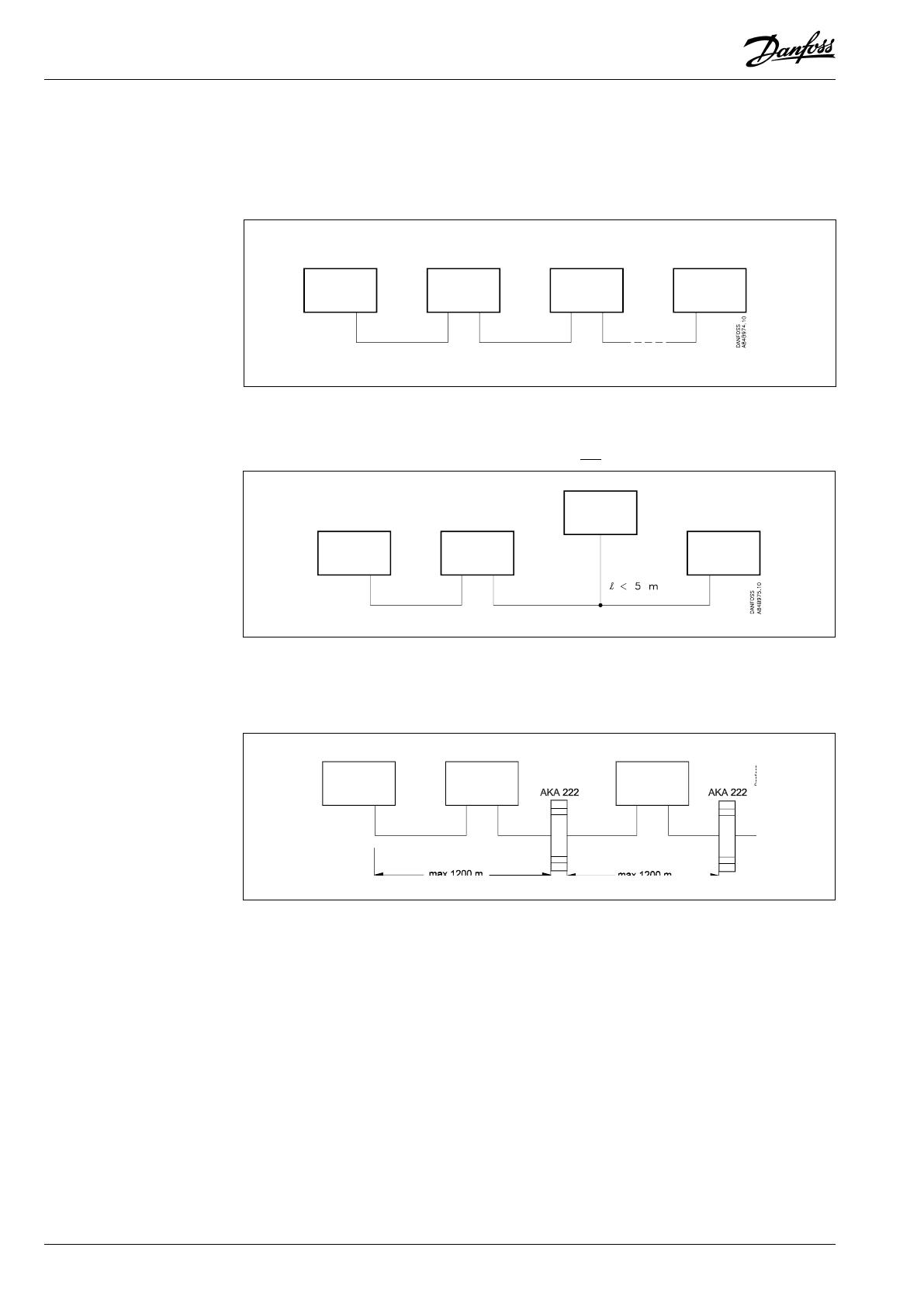
In general the cable should be looped from the rst unit to the next unit, and so on.
How the cable is to be connected to the individual controllers is described in the section “Terminals”.
Exceptionally, branch connections may be allowed from the “main cable”. This is however only
allowed, if the distance from the “main cable” to the unit is
less than 5 m.
The length of the data transmission is limited to 1200 m, if the signal is not to be amplied. When
dis-
tances are greater, an amplier type AKA 222 must be mounted for each 1200 m (cf. also the section
“Number of controllers”).
Cable layout

DANBUSS Installation Guide RC0XA402 © Danfoss 07/2006 5
A DANBUSS system may consist of as many as 256 x 124 addressable units. Each unit is identied with
a system address numbered, as follows: “yyy : xxx”. In this designation, yyy indicates a network number
and xxx a controller address. There are the following limitations:
- A system may consist of up to 256 networks, each one of which is controlled by a gateway.
- Within each network, up to 124 addressable units may be installed. Ampliers type AKA 222 do not
occupy an address. Control panel type AKA 21 accepts one address for each panel, but only when
the panel is connected to the network.
- An amplier type AKA 222 must be used for each 25 addressable units.
Number of controllers
If correct data transmission is to be ensured, there are strict requirements for the treatment of the
cable ends.
Generally:
- Avoid cable joints at points other than the individual controllers.
- Do not strip more of the cable than absolutely necessary.
- The correct wires in the cable must be connected to the controller. Although there are four wires in
the cable inside the screen, you cannot simply choose any colour you fancy. The wires are twisted in
pairs, and it is a requirement that a
twisted pair be used.
- If there is a screen on the cable, it must be connected to the controller at
both ends.
- When all cables have been mounted on the dierent units,
a setting must be made for each unit.
This setting indicates whether the data signal is to be retransmitted from the unit, or whether it
stops there.
On an addressable unit it is done very easily by setting a switch. At the extreme points of the data
transmission the “BUS TERM” (bus termination) switch on the unit is put in pos. ON. On all other units,
in pos. OFF. (If only one controller is mounted in the system, the switch is put in pos. ON).
For control panel type AKA 21 there are various options which are all described in the section below:
“Control panel type AKA 21”.
In a signal amplier type AKA 222 the data signal will be divided into two separate electrical units,
and each connection here will be considered as the extreme end of the data transmission. Please
refer to the section below: “Signal amplier type AKA 222”.
Cable ends
ON OFF OFF ON

6 Installation Guide RC0XA402 © Danfoss 07/2006 DANBUSS
Control panel type AKA 21 is tted with a 2 m long spiral wire and plug, so that it can be connected to
and removed from an installation, as required. Connection to the installation takes place via a socket
to which the data transmission cable is routed. Connection may be made to any controller, gateway or
amplier in the system, or the socket may be mounted in the data transmission cable.
No system address has to be set in a control panel. The system will itself nd a vacant address for it.
It is however a condition that all 124 addresses have not already been taken.
There are requirements to be complied with, if correct data transmission is to be ensured between
the units. These requirements will depend on where in the installation the control panel is to be
connected. Three connection options are depicted below:
Cable length less than 3 metres
When the cable length is less than 3 metres, the control panel may be connected directly to any
controller in the system.
If the control panel is connected in this way, the following must be done:
- The supply voltage to the control panel must be taken from the controller.
- The “BUS TERM” switch on the connected controllers must be put in pos. ON or OFF, depending on
how the data signal is retransmitted to the controllers (cf. the earlier section “Cable ends”).
(If only one controller is mounted in the system, the switch is put in pos. ON).
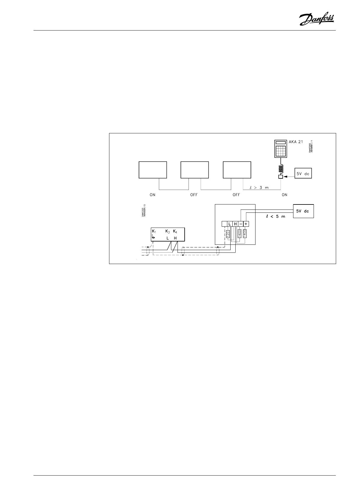
Cable length over 3 metres and control panel connected between two controllers
When the cable is over 3 metres long, the socket cannot be mounted as a branch connection; it
must instead be included as part of the data communication system.
Control panel type AKA 21
DANBUSS Installation Guide RC0XA402 © Danfoss 07/2006 7
If the control panel is connected in this way, the following must be done:
- An external supply voltage unit is added to the control panel. The distance between the control
panel’s socket and the supply voltage must not exceed 5 metres. (The requirement of the voltage
supply is 5V d.c.
± 0.2V, 100 mA).
- The “BUS TERM” switch on the connected controllers is put in pos. ON for controllers where the signal
stops, and in pos. OFF for controllers where the data signal is retransmitted.
Cable length over 3 metres and control panel is connected to one of the units at the
extreme ends
When the cable is over 3 metres long, the socket cannot be mounted as a branch connection;
it must instead be connected as part of the data communication system.
If the control panel is connected in this way, the following must be done:
- An external supply voltage unit is added to the control panel. The distance between the control
panel’s socket and the supply voltage must not exceed 5 metres. (The requirement of the voltage
supply is 5V d.c. ± 0.2V, 100 mA).
- The “BUSTERM” switch on the connected controller is put in pos. OFF (if only one controller has been
mounted in the system, put the switch in pos. ON).
- A termination has to be arranged at the control panel’s socket. This termination is carried out with
resistors, as shown in the drawing.
8 Installation Guide RC0XA402 © Danfoss 07/2006 DANBUSS
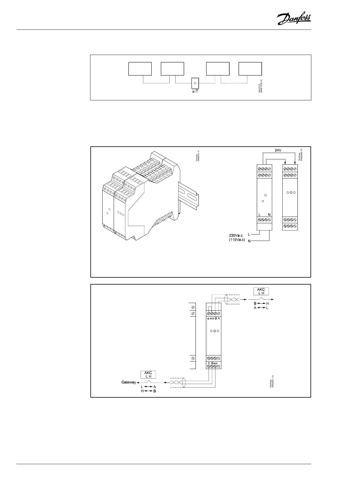
AKA 222 is used for “refreshing” the data signal when wires are long and there are many controllers
(cf. earlier).
The signal amplier “refreshes” the signal on the second output regardless of the direction.
Data
Power supply: 230 V a.c., 3 VA
DANBUSS connections: 2
Signal amplier
type AKA 22
Repeater
(Phoenix no:
2744429)
Power supply
(Phoenix no:
2938840)
AKA 222 = Power supply + Repeater
Ordering
Type AKA 222: 084B2240
DANBUSS Installation Guide RC0XA402 © Danfoss 07/2006 9
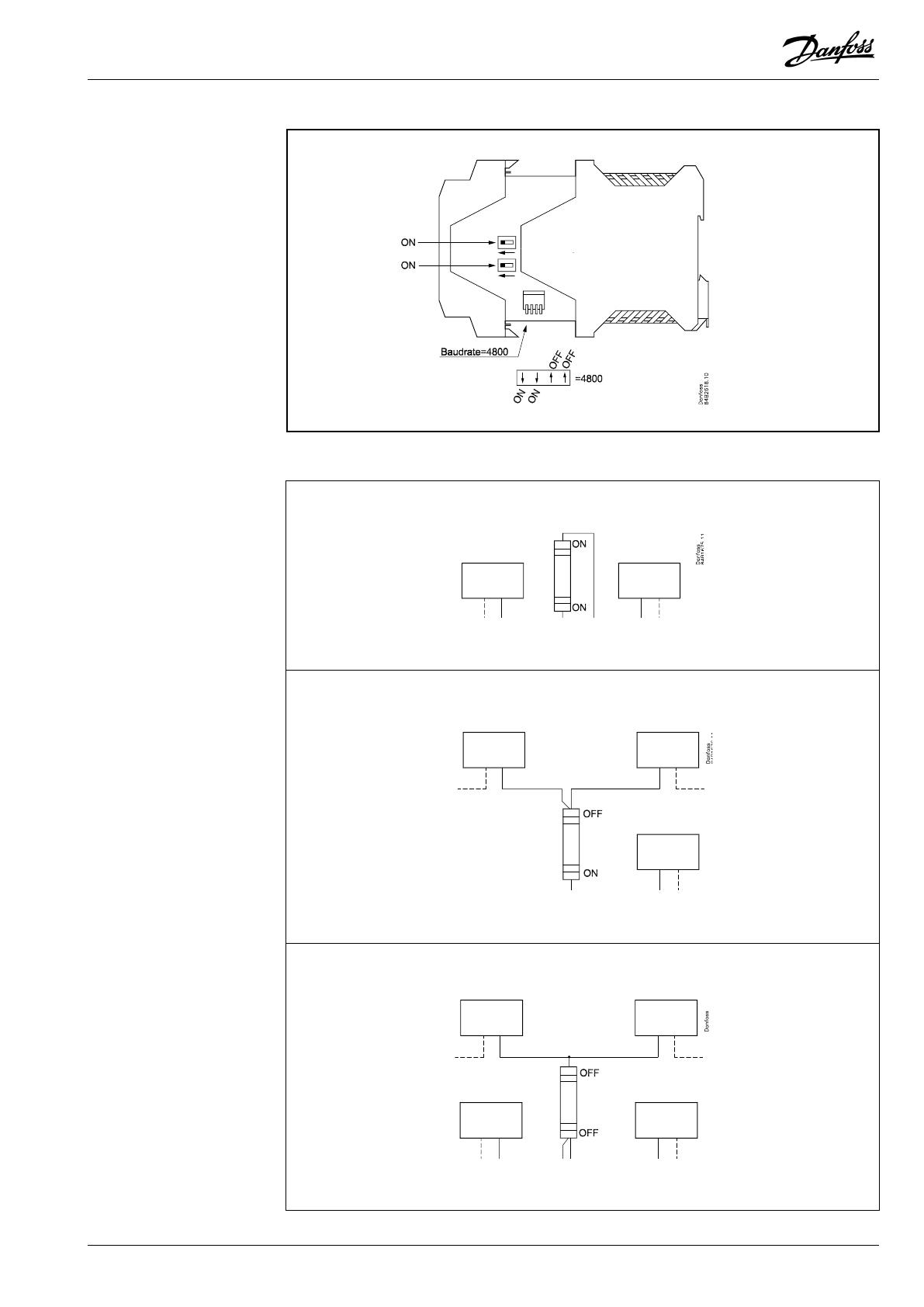
Examples of connections and how termination is carried out
1
2
3
Termination
10 Installation Guide RC0XA402 © Danfoss 07/2006 DANBUSS
The various units that can be connected to the data communication cable have the following termi-
nals:
Controller and gateway
No.
K7 +5 V
K6 Not used
K5 Not used
K4 H
K3 L
K2 0 V
K1 Screen
Terminals K3 and K4 (L and H) are loop terminals that lead the bus cable on to the next unit (L must
be connected to L, and H to H).
Terminals K2 and K7 (0/+5V) can be used for supplying voltage to one control panel type AKA 21.
Terminals
Socket for control panel (screw terminals) (Code no. 084B2071)
Control panel (9-poled D-sub plug) (Not supplied by Danfoss)
No.
9-6 No connection
5 L
4 H
3 0 V
2 +5V
1 Screen
Screen connection
No.
K1 Screen
The screen must be connected
at
both ends, and it must be
connected to K1, and nothing
else.
L H 0 V 5V

DANBUSS Installation Guide RC0XA402 © Danfoss 07/2006 11
Address coding Controllers and gateways must always be set/programmed with an address code.
Controllers
Here the address code is set with a number of switches on the unit’s printed circuit. Switches 1-7 are
for address coding (switch 8 is for setting of 50 or 60 Hz supply voltage). The address is factory-set at
0.
Switch Aderess
1 2 3 4 5 6 7 no.
1 0 0 0 0 0 0 1
0 1 0 0 0 0 0 2
1 1 0 0 0 0 0 3
0 0 1 0 0 0 0 4
1 0 1 0 0 0 0 5
0 1 1 0 0 0 0 6
1 1 1 0 0 0 0 7
0 0 0 1 0 0 0 8
1 0 0 1 0 0 0 9
0 1 0 1 0 0 0 10
1 1 0 1 0 0 0 11
0 0 1 1 0 0 0 12
1 0 1 1 0 0 0 13
0 1 1 1 0 0 0 14
1 1 1 1 0 0 0 15
0 0 0 0 1 0 0 16
1 0 0 0 1 0 0 17
0 1 0 0 1 0 0 18
1 1 0 0 1 0 0 19
0 0 1 0 1 0 0 20
1 0 1 0 1 0 0 21
0 1 1 0 1 0 0 22
1 1 1 0 1 0 0 23
0 0 0 1 1 0 0 24
1 0 0 1 1 0 0 25
0 1 0 1 1 0 0 26
1 1 0 1 1 0 0 27
0 0 1 1 1 0 0 28
1 0 1 1 1 0 0 29
0 1 1 1 1 0 0 30
Switch Address
1 2 3 4 5 6 7 no.
1 1 1 1 1 0 0 31
0 0 0 0 0 1 0 32
1 0 0 0 0 1 0 33
0 1 0 0 0 1 0 34
1 1 0 0 0 1 0 35
0 0 1 0 0 1 0 36
1 0 1 0 0 1 0 37
0 1 1 0 0 1 0 38
1 1 1 0 0 1 0 39
0 0 0 1 0 1 0 40
1 0 0 1 0 1 0 41
0 1 0 1 0 1 0 42
1 1 0 1 0 1 0 43
0 0 1 1 0 1 0 44
1 0 1 1 0 1 0 45
0 1 1 1 0 1 0 46
1 1 1 1 0 1 0 47
0 0 0 0 1 1 0 48
1 0 0 0 1 1 0 49
0 1 0 0 1 1 0 50
1 1 0 0 1 1 0 51
0 0 1 0 1 1 0 52
1 0 1 0 1 1 0 53
0 1 1 0 1 1 0 54
1 1 1 0 1 1 0 55
0 0 0 1 1 1 0 56
1 0 0 1 1 1 0 57
0 1 0 1 1 1 0 58
1 1 0 1 1 1 0 59
0 0 1 1 1 1 0 60
Switch Address
1 2 3 4 5 6 7 no.
1 1 0 1 1 0 1 91
0 0 1 1 1 0 1 92
1 0 1 1 1 0 1 93
0 1 1 1 1 0 1 94
1 1 1 1 1 0 1 95
0 0 0 0 0 1 1 96
1 0 0 0 0 1 1 97
0 1 0 0 0 1 1 98
1 1 0 0 0 1 1 99
0 0 1 0 0 1 1 100
1 0 1 0 0 1 1 101
0 1 1 0 0 1 1 102
1 1 1 0 0 1 1 103
0 0 0 1 0 1 1 104
1 0 0 1 0 1 1 105
0 1 0 1 0 1 1 106
1 1 0 1 0 1 1 107
0 0 1 1 0 1 1 108
1 0 1 1 0 1 1 109
0 1 1 1 0 1 1 110
1 1 1 1 0 1 1 111
0 0 0 0 1 1 1 112
1 0 0 0 1 1 1 113
0 1 0 0 1 1 1 114
1 1 0 0 1 1 1 115
0 0 1 0 1 1 1 116
1 0 1 0 1 1 1 117
0 1 1 0 1 1 1 118
1 1 1 0 1 1 1 119
0 0 0 1 1 1 1 120
1 0 0 1 1 1 1 121
0 1 0 1 1 1 1 122
1 1 0 1 1 1 1 123
Cannot be used 124
Master gateway 125
Switch Address
1 2 3 4 5 6 7 no.
1 0 1 1 1 1 0 61
0 1 1 1 1 1 0 62
1 1 1 1 1 1 0 63
0 0 0 0 0 0 1 64
1 0 0 0 0 0 1 65
0 1 0 0 0 0 1 66
1 1 0 0 0 0 1 67
0 0 1 0 0 0 1 68
1 0 1 0 0 0 1 69
0 1 1 0 0 0 1 70
1 1 1 0 0 0 1 71
0 0 0 1 0 0 1 72
1 0 0 1 0 0 1 73
0 1 0 1 0 0 1 74
1 1 0 1 0 0 1 75
0 0 1 1 0 0 1 76
1 0 1 1 0 0 1 77
0 1 1 1 0 0 1 78
1 1 1 1 0 0 1 79
0 0 0 0 1 0 1 80
1 0 0 0 1 0 1 81
0 1 0 0 1 0 1 82
1 1 0 0 1 0 1 83
0 0 1 0 1 0 1 84
1 0 1 0 1 0 1 85
0 1 1 0 1 0 1 86
1 1 1 0 1 0 1 87
0 0 0 1 1 0 1 88
1 0 0 1 1 0 1 89
0 1 0 1 1 0 1 90
In the table “1” = ON and “0” = OFF
Gateway
The address code for gateways is programmed via the control panel.
The gateway is factory-set with address No. 125.
It will always be the gateway with address 125 which will be the master on the network.
Remember to change the addresses, if there are several gateways.
This setting
must be changed before the gateway is connected to the data communication network.
Connect a control panel type AKA 21 as the only unit on the gateway’s DANBUSS terminals, and make
the setting.

12 Installation Guide RC0XA402 © Danfoss 07/2006 DANBUSS
Danfoss can accept no responsibility for possible errors in catalogues, brochures and other printed material. Danfoss reserves the right to alter its products without notice. This also applies to products
already on order provided that such alternations can be made without subsequential changes being necessary in specications already agreed.
All trademarks in this material are property of the respecitve companies. Danfoss and Danfoss logotype are trademarks of Danfoss A/S. All rights reserved.
DE-BD
/