Page is loading ...


MAXinBOX FANCOIL 4CH2P / 2CH2P v2
http://www.zennio.com Technical Support: http://support.zennio.com
2
CONTENTS
Contents ........................................................................................................................................ 2
1 Introduction .......................................................................................................................... 3
1.1 MAXinBOX FANCOIL 4CH2P / 2CH2P v2........................................................................... 3
1.2 Installation ........................................................................................................................ 4
1.3 Start-Up and Power Loss .................................................................................................. 5
2 Configuration......................................................................................................................... 6
2.1 General ............................................................................................................................. 6
2.2 Outputs............................................................................................................................. 8
2.3 Logic Functions ................................................................................................................. 9
2.4 Scene Temporisation ...................................................................................................... 10
2.5 Manual Control .............................................................................................................. 12
ANNEX I. Communication Objects............................................................................................... 16

MAXinBOX FANCOIL 4CH2P / 2CH2P v2
http://www.zennio.com Technical Support: http://support.zennio.com
3
1 INTRODUCTION
1.1 MAXinBOX FANCOIL 4CH2P / 2CH2P v2
MAXinBOX FANCOIL 4CH2P / 2CH2P v2 from Zennio are KNX actuators aimed at
covering the climate control needs in KNX environments with two-pipe fan coil units
where both the fan speed and the opening of the water pipe valves are controlled by
relays.
Model 4CH2P provides 16 relay outputs while model 2CH2P incorporates 8 relay
outputs, which makes them capable of controlling, respectively, up to 4 and up to 2 two-
tube fan coil units through three relays for the fan speed selection, and a fourth one for
the valve control.
The most outstanding features of MAXinBOX FANCOIL 4CH2P / 2CH2P are:
16 / 8 relay outputs, respectively, configurable as 4 / 2 two-pipe fan coil
modules where both the fan speed control and the valve control are performed
through relays.
20 customisable, multi-operation logic functions.
Scene-triggered action control, with an optional delay in the execution.
Manual operation / supervision of the relay outputs through the on-board
pushbuttons and LEDs.
Heartbeat or periodical “still-alive” notification.
Relay Switches Counter.

MAXinBOX FANCOIL 4CH2P / 2CH2P v2
http://www.zennio.com Technical Support: http://support.zennio.com
4
1.2 INSTALLATION
MAXinBOX FANCOIL 4CH2P / 2CH2P connects to the KNX bus through the on-board
KNX connector. Once the device is provided with power from the KNX bus, both the
individual address and the associated application program may be downloaded.
This device does not need any additional external power since it is entirely powered
through the KNX bus.
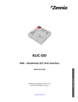
Figure 1 MAXinBOX FANCOIL 4CH2P v2. Elements.
Note: the above figure is completely analogous for MAXinBOX 2CH2P v2.
The main elements of the device are described next.
Prog./Test Pushbutton (2): a short press on this button sets the device into
the programming mode, making the associated LED (3) light in red.
Note: if this button is held while plugging the device into the KNX bus, the
device will enter into safe mode. In such case, the LED will blink in red every
0.5 seconds.
Outputs (1 and 4): output ports for the insertion of the stripped cables of the
systems being controlled by the actuator (see section 2.2). Please secure the
connection by means of the on-board screws.
Manual control pushbuttons (6): pushbuttons for a direct control of the relays
during the set-up process. See section 2.52.5.
1
5
6
4
2
3
7
8
1. Upper outputs
2. Programming/Test button
3. Programming/Test LED
4. Lower outputs
5. Output status LED indicator
6. Output control button
7. KNX connector
8. Fixing clamp

MAXinBOX FANCOIL 4CH2P / 2CH2P v2
http://www.zennio.com Technical Support: http://support.zennio.com
5
For detailed information about the technical features of the device and for safety
instructions or about the installation process, please refer to the corresponding
Datasheet, bundled with the original package of the device and also available at
www.zennio.com.
1.3 START-UP AND POWER LOSS
During the start-up of the device, the Prog./Test LED will blink in blue colour for a few
seconds before the device is ready. External orders will not be executed during this time,
but afterwards.
Depending on the configuration, some specific actions will also be performed during the
start-up. For example, the integrator can set whether the output channels should switch
to a particular state and whether the device should send certain objects to the bus after
the power recovery. Please consult the next sections of this document for further details.
On the other hand, when a bus power failure takes place, MAXinBOX will interrupt any
pending actions, and will save its state so it can be recovered once the power supply is
restored.

MAXinBOX FANCOIL 4CH2P / 2CH2P v2
http://www.zennio.com Technical Support: http://support.zennio.com
6
2 CONFIGURATION
2.1 GENERAL
After importing the corresponding database in ETS and adding the device into the
topology of the desired project, the configuration process begins by entering the
Parameters tab of the device.
ETS PARAMETERISATION
The only parameterisable screen available by default is General. From this screen it is
possible to activate/deactivate all the required functionality.
Figure 2. General screen
Outputs [disabled/enabled]
1
: enables o disables the “Outputs” tab on the left
menu. See section 2.2 for more details.
Logic Functions [disabled/enabled]: enables o disables the “Logic Functions”
tab on the left menu. See section 2.3 for more details.
Scene Temporization [disabled/enabled]: enables o disables the “Scene
Temporization” tab on the left menu. See section 2.4 for more details.
1
The default values of each parameter will be highlighted in blue in this document, as follows:
[default/rest of options].

MAXinBOX FANCOIL 4CH2P / 2CH2P v2
http://www.zennio.com Technical Support: http://support.zennio.com
7
Manual Control [disabled/enabled]: enables o disables the “Manual Control”
tab on the left menu. See section 2.5 for more details.
Sending of Indication Objects (0 and 1) on Bus Voltage Recovery
[disabled/enabled]: this parameter lets the integrator activate two new
communication objects (“Reset 0” and “Reset 1”), which will be sent to the KNX
bus with values “0” and “1” respectively whenever the device begins operation
(for example, after a bus power failure). It is possible to parameterise a certain
delay [0…255] to this sending.
Figure 3. Sending of Indication objects on bus voltage recovery
Heartbeat (Periodic Alive Notification) [disabled/enabled]: this parameter
lets the integrator incorporate a one-bit object to the project (“[Heartbeat]
Object to Send ‘1’”) that will be sent periodically with value “1” to notify that
the device is still working (still alive).
Figure 4. Heartbeat (Periodical Alive Notification).
Note: The first sending after download or bus failure takes place with a delay
of up to 255 seconds, to prevent bus overload. The following sendings match
the period set.
Show Relay Switches Counter Objects [disabled/enabled]: enables two
communication objects to keep track of the number of switches performed by
each of the relays ("[Relay X] Number of Switches") and the maximum
number of switches carried out in a minute ("[Relay X] Maximum Switches
per Minute").

MAXinBOX FANCOIL 4CH2P / 2CH2P v2
http://www.zennio.com Technical Support: http://support.zennio.com
8
2.2 OUTPUTS
MAXinBOX FANCOIL 4CH2P / 2CH2P v2 actuator incorporates 16 / 8 relay outputs,
which can be configured as fan Coil modules, which allow the control of the fan and the
valve of two-pipe fan coil units (it is possible to control up to 4 / 2 independent fancoil
blocks, respectively).
For detailed information about the functionality and the configuration of the fancoil
modules, please refer to the following specific manual “Fan coil ‘Relays’”, available
within the MAXinBOX FANCOIL 4CH2P / 2CH2P v2 product section at the Zennio
website (www.zennio.com).
Note: Note that these devices only support two-pipe fan coils with On/Off valves.
Therefore, any references to four-pipe fan coils and 3-Point valves do not apply to them.

MAXinBOX FANCOIL 4CH2P / 2CH2P v2
http://www.zennio.com Technical Support: http://support.zennio.com
9
2.3 LOGIC FUNCTIONS
This module makes it possible to perform numeric and binary operations to incoming
values received from the KNX bus, and to send the results through other communication
objects specifically enabled for this purpose.
Up to 20 different and independent functions can be implemented, each of them
entirely customisable and consisting in up to 4 consecutive operations each one.
The execution of each function can depend on a configurable condition, which will be
evaluated every time the function is triggered through specific, parameterisable
communication objects. The result after executing the operations of the function can also
be evaluated according to certain conditions and afterwards sent (or not) to the KNX
bus, which can be done every time the function is executed, periodically or only when
the result differs from the last one.
Please refer to the “Logic Functions” user manual, available within the MAXinBOX
FANCOIL 4CH2P / 2CH2P v2 product section at the Zennio homepage,
www.zennio.com, for detailed information about the functionality and the configuration of
the related parameters.

MAXinBOX FANCOIL 4CH2P / 2CH2P v2
http://www.zennio.com Technical Support: http://support.zennio.com
10
2.4 SCENE TEMPORISATION
The scene temporisation allows imposing delays over the scenes of the outputs.
These delays are defined in parameters, and can be applied to the execution of one or
more scenes that may have been configured.
Please bear in mind that, as multiple delayed scenes can be configured for each
individual output / shutter channel / fan coil module, in case of receiving an order to
execute one of them when a previous temporisation is still pending for that output /
channel / module, such temporisation will be interrupted and only the delay and the
action of the new scene will be executed.
ETS PARAMETERISATION
Prior to setting the scene temporisation, it is necessary to have one or more scenes
configured in some of the outputs. When entering the Configuration window under Scene
Temporization, all configured scenes will be listed, together with a few checkboxes to
select which of them need to be temporised, as shown in Figure 5.
Figure 5. Scene Temporization
Enabling a certain scene number n brings a new tab with such name to the menu on the
left, from which it is possible to configure the temporisation of that scene for each of the
outputs where it has been configured.

MAXinBOX FANCOIL 4CH2P / 2CH2P v2
http://www.zennio.com Technical Support: http://support.zennio.com
11
Figure 6. Configuration of Scene Temporization
Therefore, parameter “Scene m. Z Delay” [0…3600 [s] / 0…1440 [min] / 0…24 [h]],
defines the delay that will be applied to the action defined in Z for the execution of scene
m (where Z may be a specific individual output, shutter channel or fan coil module).
Note: In the configuration of a scene of an output / shutter channel / fancoil it is possible
to parameterize several scenes with the same scene number. This means that several
delay parameters associated with the same output appear in the configuration tab of the
delays of that scene. With this parameterization, the behavior will be as follows: the
action and delay of the first scene parameterized with the same scene number will
always prevail, where the highest priority scene is 1 (the first in the scene configuration
tab) and the lowest priority is the last.

MAXinBOX FANCOIL 4CH2P / 2CH2P v2
http://www.zennio.com Technical Support: http://support.zennio.com
12
2.5 MANUAL CONTROL
MAXinBOX FANCOIL 4CH2P / 2CH2P v2 allows manually switching the state of its
output relays through the respective pushbuttons on the top of the device. A specific
pushbutton is therefore available per output.
Manual operation can be done in two different ways, named as Test On mode (for
testing purposes during the configuration of the device) and Test Off mode (for a normal
use, anytime). Whether both, only one, or none of these modes should be accessible
needs to be parameterised in ETS. Moreover, it is possible to enable a specific binary
object for locking and unlocking the manual control in runtime.
Notes:
The Test Off mode will be active (unless it has been disabled by parameter)
after a download or a reset with no need of a specific activation – the
pushbuttons will respond to user presses from the start.
On the contrary, switching to the Test On mode (unless disabled by
parameter) needs to be done by long-pressing the Prog/Test button (for at least
three seconds), until the LED is no longer red and turns yellow. From that
moment, once the button is released, the LED light will remain green to confirm
that the device has switched from the Test Off mode to the Test On mode. After
that, an additional press will turn the LED yellow and then off, once the button
is released. This way, the device leaves the Test On mode. Note that it will also
leave this mode if a bus power failure takes place or if a manual control lock is
sending from KNX bus.
Test Off Mode
Under the Test Off Mode, the outputs can be controlled through both their communication
objects and the actual pushbuttons located on the top of the device.
When one of these buttons is pressed, the output will behave as if an order had been
received through the corresponding communication object, depending on whether the
output is configured as either an individual output, as a shutter channel or as a fan coil.

MAXinBOX FANCOIL 4CH2P / 2CH2P v2
http://www.zennio.com Technical Support: http://support.zennio.com
13
Fan Coil module: the behaviour will depend on whether a fan-labelled or a
valve-labelled button is pressed:
➢ Fan: for this type of buttons, it must be taken into account that there are two
types of control for the fan speed:
• Switching control: a short or long press will switch the relays to set the
selected speed, unless it matches the current speed – in such case all
the relays will be opened (speed 0). The associated LEDs will indicate
the state of the fan speed control relays (on = relay closed; off = relay
open).
• Accumulation control: a short or long press switch to the selected
speed, closing the relay associated with that speed, and also the relays
assigned to the lower speeds, unless it matches the current speed – in
such case all the relays will be opened (speed 0). The associated LEDs
will indicate the state of the fan speed control relays (on = relay closed;
off = relay open).
Note: the behaviour of the relays will depend on the parameterisation, i.e.,
on the number of fan speeds, and on the delay between switches.
➢ Valve: a short or long press will switch the current status of the relay and
therefore of the valve. The LED will show the state of the relay anytime (on
= relay closed; off = relay open).
Disabled output: outputs disabled by parameter will not react to button
presses under the Test Off mode.
Regarding the lock, timer, alarm and scene functions, the device will behave under the
Test Off mode as usual. Button presses during this mode are entirely analogous to the
reception of the corresponding orders from the KNX bus.
Test On Mode
After entering the Test On mode, it will only be possible to control the outputs through
the on-board pushbuttons. Orders received through communication objects will be
ignored, with independence of the channel or the output they are addressed to.

MAXinBOX FANCOIL 4CH2P / 2CH2P v2
http://www.zennio.com Technical Support: http://support.zennio.com
14
Depending on whether the output has been parameterized as an individual output or as
part of a shutter channel, the reactions to the button presses will differ.
The behaviour is similar to that of the Test Off mode, although in this case the three fan
speeds are supposed available.
As described previously if the device is in Test On mode, any command sent from the
KNX bus to the actuator will not affect the outputs and no status objects will be sent (only
periodically timed objects such as Heartbeat or logic functions will continue to be sent to
the bus) while Test ON mode is active. However, in the case of the "Alarm" and "Block"
objects, although in Test ON mode the actions received by each object are not taken into
account, the evaluation of their status is carried out when exiting this mode, so that any
change in the alarm status or blocking of the outputs while Test ON mode is active is
taken into account when exiting this mode and is updated with the last status detected.
Important: the device is delivered from factory with all the outputs disabled, and with
both manual modes (Test Off and Test On) enabled.
ETS PARAMETERISATION
The Manual Control is configured from the Configuration tab itself under Manual
Control.
The only two parameters are:
Figure 7. Manual Control
Manual Control [Disabled / Only Test Off Mode / Only Test On Mode / Test
Off Mode + Test On Mode]. Depending on the selection, the device will permit
using the manual control under the Test Off, the Test On, or both modes. Note
that, as stated before, using the Test Off mode does not require any special

MAXinBOX FANCOIL 4CH2P / 2CH2P v2
http://www.zennio.com Technical Support: http://support.zennio.com
15
action, while switching to the Test On mode does require long-pressing the
Prog/Test button.
Manual Control Lock [enabled/disabled]: unless the above parameter has
been “Disabled”, the Lock Manual Control parameter provides an optional
procedure for locking the manual control in runtime. When this checkbox is
enabled, object “Manual Control Lock” turns visible, as well as two more
parameters:
➢ Value [0 = Lock; 1 = Unlock / 0 = Unlock; 1 = Lock]: defines whether the
manual control lock/unlock should take place respectively upon the
reception (through the aforementioned object) of values “0” and “1”, or the
opposite.
➢ Initialization [Unlocked / Locked / Last Value]: sets how the lock state of
the manual control should remain after the device start-up (after an ETS
download or a bus power failure). “Last Value” (default; on the very first start-
up, this will be Unlocked.

MAXinBOX FANCOIL 4CH2P / 2CH2P v2
http://www.zennio.com Technical Support: http://support.zennio.com
16
ANNEX I. COMMUNICATION OBJECTS
“Functional range” shows the values that, with independence of any other values permitted by the bus according to the object size, may be of any
use or have a particular meaning because of the specifications or restrictions from both the KNX standard or the application programme itself.
Note: Some of the numbers in the first column are only applicable to MAXinBOX FANCOIL 4CH2P / 2CH2P v2.
Number
Size
I/O
Flags
Data type (DPT)
Functional Range
Name
Function
1
1 Bit
C T - - -
DPT_Trigger
0/1
Reset 0
Voltage Recovery -> Sending of 0
2
1 Bit
C T - - -
DPT_Trigger
0/1
Reset 1
Voltage Recovery -> Sending of 1
3
1 Bit
I
C - - W -
DPT_Enable
0/1
Lock Manual Control
0 = Lock; 1 = Unlock
1 Bit
I
C - - W -
DPT_Enable
0/1
Lock Manual Control
0 = Unlock; 1 = Lock
4
1 Bit
C T - - -
DPT_Trigger
0/1
[Heartbeat] Object to Send '1'
Sending of '1' Periodically
606
1 Byte
I
C - - W U
DPT_SceneControl
0-63; 128-191
[Fan Coil] Scenes
0 - 63 (Execute 1 - 64); 128 - 191
(Save 1 - 64)
607, 640, 673, 706
1 Bit
I
C - - W U
DPT_Switch
0/1
[FCx] On/Off
0 = Off; 1 = On
608, 641, 674, 707
1 Bit
O
C T R - -
DPT_Switch
0/1
[FCx] On/Off (Status)
0 = Off; 1 = On
609, 642, 675, 708
1 Bit
I
C - - W U
DPT_Heat_Cool
0/1
[FCx] Mode
0 = Cool; 1 = Heat
610, 643, 676, 709
1 Bit
O
C T R - -
DPT_Heat_Cool
0/1
[FCx] Mode (Status)
0 = Cool; 1 = Heat
611, 644, 677, 710
1 Bit
I
C - - W U
DPT_Switch
0/1
[FCx] Fan: Manual/Automatic
0 = Automatic; 1 = Manual
1 Bit
I
C - - W U
DPT_Switch
0/1
[FCx] Fan: Manual/Automatic
0 = Manual; 1 = Automatic
612, 645, 678, 711
1 Bit
O
C T R - -
DPT_Switch
0/1
[FCx] Fan: Manual/Automatic (Status)
0 = Automatic; 1 = Manual
1 Bit
O
C T R - -
DPT_Switch
0/1
[FCx] Fan: Manual/Automatic (Status)
0 = Manual; 1 = Automatic
613, 646, 679, 712
1 Bit
I
C - - W U
DPT_Step
0/1
[FCx] Manual Fan: Step Control
0 = Down; 1 = Up
614, 647, 680, 713
1 Bit
I
C - - W U
DPT_Switch
0/1
[FCx] Manual Fan: Speed 0
0 = Off; 1 = On
615, 648, 681, 714
1 Bit
I
C - - W U
DPT_Switch
0/1
[FCx] Manual Fan: Speed 1
0 = Off; 1 = On
616, 649, 682, 715
1 Bit
I
C - - W U
DPT_Switch
0/1
[FCx] Manual Fan: Speed 2
0 = Off; 1 = On
617, 650, 683, 716
1 Bit
I
C - - W U
DPT_Switch
0/1
[FCx] Manual Fan: Speed 3
0 = Off; 1 = On
618, 651, 684, 717
1 Bit
O
C T R - -
DPT_Switch
0/1
[FCx] Fan: Speed 0 (Status)
0 = Off; 1 = On
619, 652, 685, 718
1 Bit
O
C T R - -
DPT_Switch
0/1
[FCx] Fan: Speed 1 (Status)
0 = Off; 1 = On
620, 653, 686, 719
1 Bit
O
C T R - -
DPT_Switch
0/1
[FCx] Fan: Speed 2 (Status)
0 = Off; 1 = On
621, 654, 687, 720
1 Bit
O
C T R - -
DPT_Switch
0/1
[FCx] Fan: Speed 3 (Status)
0 = Off; 1 = On

MAXinBOX FANCOIL 4CH2P / 2CH2P v2
http://www.zennio.com Technical Support: http://support.zennio.com
17
622, 655, 688, 721
1 Byte
I
C - - W U
DPT_Value_1_Ucount
0 - 255
[FCx] Manual Fan: Enumeration Control
S0 = 0; S1 = 1; S2 = 2; S3 = 3
1 Byte
I
C - - W U
DPT_Value_1_Ucount
0 - 255
[FCx] Manual Fan: Enumeration Control
S0 = 0; S1 = 1; S2 = 2
1 Byte
I
C - - W U
DPT_Value_1_Ucount
0 - 255
[FCx] Manual Fan: Enumeration Control
S0 = 0; S1 = 1
623, 656, 689, 722
1 Byte
O
C T R - -
DPT_Value_1_Ucount
0 - 255
[FCx] Fan: Speed Enumeration (Status)
S0 = 0; S1 = 1; S2 = 2; S3 = 3
1 Byte
O
C T R - -
DPT_Value_1_Ucount
0 - 255
[FCx] Fan: Speed Enumeration (Status)
S0 = 0; S1 = 1; S2 = 2
1 Byte
O
C T R - -
DPT_Value_1_Ucount
0 - 255
[FCx] Fan: Speed Enumeration (Status)
S0 = 0; S1 = 1
624, 657, 690, 723
1 Byte
I
C - - W U
DPT_Scaling
0% - 100%
[FCx] Manual Fan: Percentage Control
S0 = 0%; S1 = 0,4-33,3%; S2 =
33,7-66,7%; S3 = 67,1-100%
1 Byte
I
C - - W U
DPT_Scaling
0% - 100%
[FCx] Manual Fan: Percentage Control
S0 = 0%; S1 = 1-50%; S2 = 51-
100%
1 Byte
I
C - - W U
DPT_Scaling
0% - 100%
[FCx] Manual Fan: Percentage Control
S0 = 0%; S1 = 1-100%
625, 658, 691, 724
1 Byte
O
C T R - -
DPT_Scaling
0% - 100%
[FCx] Fan: Speed Percentage (Status)
S0 = 0%; S1 = 33,3%; S2 = 66,6%;
S3 = 100%
1 Byte
O
C T R - -
DPT_Scaling
0% - 100%
[FCx] Fan: Speed Percentage (Status)
S0 = 0%; S1 = 1-50%; S2 = 51-
100%
1 Byte
O
C T R - -
DPT_Scaling
0% - 100%
[FCx] Fan: Speed Percentage (Status)
S0 = 0%; S1 = 1-100%
626, 659, 692, 725
1 Byte
I
C - - W U
DPT_Scaling
0% - 100%
[FCx] Cooling Fan: Continuous Control
0 - 100%
1 Byte
I
C - - W U
DPT_Scaling
0% - 100%
[FCx] Cooling Valve: PI Control
(Continuous)
0 - 100%
627, 660, 693, 726
1 Byte
I
C - - W U
DPT_Scaling
0% - 100%
[FCx] Heating Fan: Continuous Control
0 - 100%
1 Byte
I
C - - W U
DPT_Scaling
0% - 100%
[FCx] Heating Valve: PI Control
(Continuous)
0 - 100%
628, 661, 694, 727
1 Bit
I
C - - W U
DPT_OpenClose
0/1
[FCx] Cooling Valve: Control Variable (1
bit)
0 = Open Valve; 1 = Close Valve
1 Bit
I
C - - W U
DPT_Switch
0/1
[FCx] Cooling Valve: Control Variable (1
bit)
0 = Close Valve; 1 = Open Valve
629, 662, 695, 728
1 Bit
I
C - - W U
DPT_OpenClose
0/1
[FCx] Heating Valve: Control Variable (1
bit)
0 = Open Valve; 1 = Close Valve
1 Bit
I
C - - W U
DPT_Switch
0/1
[FCx] Heating Valve: Control Variable (1
bit)
0 = Close Valve; 1 = Open Valve
630, 663, 696, 729
1 Bit
O
C T R - -
DPT_OpenClose
0/1
[FCx] Cooling Valve (Status)
0 = Open; 1 = Closed
1 Bit
O
C T R - -
DPT_Switch
0/1
[FCx] Cooling Valve (Status)
0 = Closed; 1 = Open
1 Bit
O
C T R - -
DPT_OpenClose
0/1
[FCx] Valve (Status)
0 = Open; 1 = Closed
1 Bit
O
C T R - -
DPT_Switch
0/1
[FCx] Valve (Status)
0 = Closed; 1 = Open
631, 664, 697, 730
1 Bit
O
C T R - -
DPT_OpenClose
0/1
[FCx] Heating Valve (Status)
0 = Open; 1 = Closed
1 Bit
O
C T R - -
DPT_Switch
0/1
[FCx] Heating Valve (Status)
0 = Closed; 1 = Open
632, 665, 698, 731
1 Bit
O
C T R - -
DPT_Switch
0/1
[FCx] Cooling Valve: Anti-Seize Protection
(Status)
0 = Not Active; 1 = Active

MAXinBOX FANCOIL 4CH2P / 2CH2P v2
http://www.zennio.com Technical Support: http://support.zennio.com
18
1 Bit
O
C T R - -
DPT_Switch
0/1
[FCx] Valve: Anti-Seize Protection
(Status)
0 = Not Active; 1 = Active
633, 666, 699, 732
1 Bit
O
C T R - -
DPT_Switch
0/1
[FCx] Heating Valve: Anti-Seize Protection
(Status)
0 = Not Active; 1 = Active
634, 667, 700, 733
1 Byte
O
C T R - -
DPT_Scaling
0% - 100%
[FCx] Valve (Status)
0 - 100%
1 Byte
O
C T R - -
DPT_Scaling
0% - 100%
[FCx] Cooling Valve (Status)
0 - 100%
635, 668, 701, 734
1 Byte
O
C T R - -
DPT_Scaling
0% - 100%
[FCx] Heating Valve (Status)
0 - 100%
636, 669, 702, 735
1 Bit
O
C T R - -
DPT_Bool
0/1
[FCx] Control Value - Error
0 = No Error; 1 = Error
637, 670, 703, 736
2 Bytes
I
C - - W U
DPT_Value_Temp
-273.00º - 670760.00º
[FCx] Ambient Temperature
Ambient Temperature
638, 671, 704, 737
2 Bytes
I
C - - W U
DPT_Value_Temp
-273.00º - 670760.00º
[FCx] Setpoint Temperature
Setpoint Temperature
639, 672, 705, 738
2 Bytes
I/O
C T R W
U
DPT_TimePeriodMin
0 - 65535
[FCx] Duration of Manual Control
0 = Endless; 1 - 1440 min
2 Bytes
I/O
C T R W
U
DPT_TimePeriodHrs
0 - 65535
[FCx] Duration of Manual Control
0 = Endless; 1 - 24 h
805, 806, 807, 808,
809, 810, 811, 812,
813, 814, 815, 816,
817, 818, 819, 820,
821, 822, 823, 824,
825, 826, 827, 828,
829, 830, 831, 832,
833, 834, 835, 836,
837, 838, 839, 840,
841, 842, 843, 844,
845, 846, 847, 848,
849, 850, 851, 852,
853, 854, 855, 856,
857, 858, 859, 860,
861, 862, 863, 864,
865, 866, 867, 868
1 Bit
I
C - - W -
DPT_Bool
0/1
[LF] (1-Bit) Data Entry x
Binary Data Entry (0/1)
869, 870, 871, 872,
873, 874, 875, 876,
877, 878, 879, 880,
881, 882, 883, 884,
885, 886, 887, 888,
889, 890, 891, 892,
893, 894, 895, 896,
897, 898, 899, 900
1 Byte
I
C - - W -
DPT_Value_1_Ucount
0 - 255
[LF] (1-Byte) Data Entry x
1-Byte Data Entry (0-255)
901, 902, 903, 904,
905, 906, 907, 908,
909, 910, 911, 912,
913, 914, 915, 916,
917, 918, 919, 920,
2 Bytes
I
C - - W -
1.xxx
0/1
[LF] (2-Byte) Data Entry x
2-Byte Data Entry

MAXinBOX FANCOIL 4CH2P / 2CH2P v2
http://www.zennio.com Technical Support: http://support.zennio.com
19
921, 922, 923, 924,
925, 926, 927, 928,
929, 930, 931, 932
933, 934, 935, 936,
937, 938, 939, 940,
941, 942, 943, 944,
945, 946, 947, 948
4 Bytes
I
C - - W -
DPT_Value_4_Count
-2147483648 - 2147483647
[LF] (4-Byte) Data Entry x
4-Byte Data Entry
949, 950, 951, 952,
953, 954, 955, 956,
957, 958, 959, 960,
961, 962, 963, 964,
965, 966, 967, 968,
969, 970, 971, 972,
973, 974, 975, 976,
977, 978
1 Bit
O
C T R - -
DPT_Bool
0/1
[LF] Function x - Result
(1-Bit) Boolean
1 Byte
O
C T R - -
DPT_Value_1_Ucount
0 - 255
[LF] Function x - Result
(1-Byte) Unsigned
2 Bytes
O
C T R - -
DPT_Value_2_Ucount
0 - 65535
[LF] Function x - Result
(2-Byte) Unsigned
4 Bytes
O
C T R - -
DPT_Value_4_Count
-2147483648 - 2147483647
[LF] Function x - Result
(4-Byte) Signed
1 Byte
O
C T R - -
DPT_Scaling
0% - 100%
[LF] Function x - Result
(1-Byte) Percentage
2 Bytes
O
C T R - -
DPT_Value_2_Count
-32768 - 32767
[LF] Function x - Result
(2-Byte) Signed
2 Bytes
O
C T R - -
DPT_Value_Temp
-273.00º - 670760.00º
[LF] Function x - Result
(2-Byte) Float
979, 981, 983, 985,
987, 989, 991, 993,
995, 997, 999, 1001,
1003, 1005, 1007,
1009
4 Bytes
O
C T R - -
DPT_Value_4_Ucount
0 - 4294967295
[Relay x] Number of Switches
Number of Switches
980, 982, 984, 986,
988, 990, 992, 994,
996, 998, 1000,
1002, 1004, 1006,
1008, 1010
2 Bytes
O
C T R - -
DPT_Value_2_Ucount
0 - 65535
[Relay x] Maximum Switches per Minute
Maximum Switches per Minute

/