Page is loading ...

SERVICE MANUAL
USA
Screw Compressor
Model: SM 8
GL---Nr.: BA---SM8.L---1.9620.80030---00
Index: 090201
L Volt L Cabinet heaters..........................
L Wye---Delta Start L 115 V receptacle
L D.O.L. Start L Outdoor modification
L psig L Rainhoods..........................
LLSwitchable Modulation.............................
LLSynthetic lubricant............................. ...................
L Wiring Diagram: L FoodGradelubricant.................
..............................
Serial No.:
...............................................
KAESER COMPRESSORS, Inc.
P.O. Box 946 : Fredericksburg, Virginia 22404 : Tel. (540) 898---5500 : Fax. (540) 898---5520
Back to Table of Contents

Table of Contents
Chap ter --- Pag e
i
1 Technical Specification 1 --- 1.........................................
1.1 Compressor Unit 1 --- 1.....................................................
1.2 Noise L ev el 1 --- 1..........................................................
1.3 Motor 1 --- 1...............................................................
1.4 Electrical Connection 1 --- 1.................................................
1.5 Set Point of the Safety Relief Valve 1 --- 2......................................
1.6 Installation Requirements 1 --- 2..............................................
1.7 Oil Capacities 1 --- 2........................................................
1.8 Oil recommendations 1 --- 3.................................................
1.9 Maintenance for the Electrical Motor 1 --- 5....................................
1.10 Dimensional Drawing 1 --- 5.................................................
2 Safety Regulations 2 --- 7.............................................
2.1 Explanation of Symbols and References 2 --- 7.................................
2.2 General Safety Precautions 2 --- 7............................................
2.3 Electrical Power Supply 2 --- 8...............................................
2.4 Spare Parts 2 --- 8..........................................................
2.5 Compressed Air System 2 --- 8...............................................
2.6 Environmental Protection 2 --- 9..............................................
3 General 3 --- 10.......................................................
3.1 Proper use of the Compressor 3 --- 10.........................................
3.2 Improper use 3 --- 10........................................................
3.3 Compressed Air Treatment 3 --- 10............................................
3.4 Copyright 3 --- 10............................................................
4 Transport 4 --- 11......................................................
4.1 Transport Instructions 4 --- 11.................................................
4.2 Packaging 4 --- 11...........................................................
5 Construction and Operation 5 --- 12....................................
5.1 Principle of Compression 5 --- 12..............................................
5.2 Brief Description 5 --- 12......................................................
5.3 Pipe and Instrument Flow Diagram (P & I Diagram) 5 --- 12.......................
5.4 DUAL Control 5 --- 15........................................................
5.5 QUADRO Control 5 --- 16.....................................................
5.6 VARIO Control 5 --- 17.......................................................
6 Installation 6 --- 18....................................................
6.1 Installation Requirements 6 --- 18..............................................
6.2 Connection of the Compressed Air Supply 6 --- 19...............................
6.3 Electrical Connection 6 --- 19.................................................
7 Putting into Operation 7 --- 20..........................................
7.1 Points to be Observed before Putting into Operation 7 --- 20......................
7.2 Points to be Observed before Starting the Compressor Unit 7 --- 20...............
7.3 Functional Check of the Door Interlock Switch 7 --- 21...........................
7.4 Direction of Rotation Check 7 --- 23............................................
7.5 Motor Overload Relay Adjustment 7 --- 23......................................
7.6 Setting the Air System Pressure 7 --- 23........................................
7.7 Measures to be taken before Initial Start 7 --- 24.................................
7.7.1 Pour a small quantity of oil into the air inlet port 7 --- 24..........................

Table of Contents
Chap ter --- Pag e
ii
7.7.2 Running the compressor in idle 7 --- 24........................................
7.7.3 Checklist 7 --- 25............................................................
8 Op eration 8 --- 26.....................................................
8.1 Control Panel 8 --- 26........................................................
8.2 SIGMA CONTROL 8 --- 26....................................................
8.2.1 Function keys 8 --- 27........................................................
8.2.2 Light emitting diodes and plain text display 8 --- 27..............................
8.3 Starting and Stopping the Compressor Unit 8 --- 28..............................
8.4 Acknowledgement of Alarms 8 --- 28...........................................
8.5 Acknowledgement of Service Messages 8 --- 29.................................
9 Maintenance 9 --- 30..................................................
9.1 Observe the following rules during all maintenance and servicing work: 9 --- 30.....
9.2 Regular Maintenance 9 --- 31.................................................
9.3 Opening and Closing the Compressor Cabinet 9 --- 32...........................
9.4 Checking the Drive Belt Tension 9 --- 33........................................
9.5 Drive Belt Change 9 --- 34....................................................
9.6 Cleaning or Replacing the Filter Mat 9 --- 34....................................
9.7 Cleaning or Replacing the Air Filter 9 --- 35.....................................
9.8 Servicing the Electric Motor 9 --- 36............................................
9.9 Testing the Safety Relief Valve on the Oil Separator Tank 9 --- 36..................
9.10 Venting the compressor unit 9 --- 36...........................................
9.11 Oil Filter Change 9 --- 38.....................................................
9.11.1 Removal and replacement of the oil filter cartridge 9 --- 38........................
9.12 Oil Top --- Off 9 --- 39..........................................................
9.13 Cleaning the Oil Cooler and Aftercooler 9 --- 41.................................
9.13.1 Removing and cleaning the oil cooler/air aftercooler 9 --- 41......................
9.14 Oil Change (Oil Separator Tank and Oil Cooler) 9 --- 43..........................
9.14.1 Oil change using external pressure source 9 --- 44..............................
9.14.2 Oil top---off 9 --- 45...........................................................
9.14.3 Draining the oil using own compressed air 9 --- 45...............................
9.14.4 Procedure for putting back into operation 9 --- 46...............................
9.15 Changing the Oil Separator Cartridge 9 --- 46...................................
9.16 Maintenance Schedule 9 --- 49................................................
10 Spare Parts and After Sales Service 10 --- 50.............................
10.1 Service parts and maintenance parts 10 --- 50...................................
10.2 Service and Maintenance Agreement 10 --- 50...................................
11 Appendix 11 --- 51......................................................
11.1 Wiring Diagram 11 --- 51......................................................
11.2 Trouble shooting: Possible cause---Remedy 11 --- 67..............................
11.2.1 Airend temperature is too high (greater than 167F--- 200F) 11 --- 67...............
11.2.2 Motor overload relay switches the unit off 11 --- 67................................
11.2.3 Compressor is running but produces no pressure 11 --- 68........................
11.2.4 Oil leaks out of air filter 11 --- 69................................................
11.2.5 Full---load/Idle sequence occurs too frequently (short cycles) 11 --- 69..............
11.2.6 Safety relief valve blows off 11 --- 69............................................
11.2.7 Oil inside the unit 11 --- 69.....................................................
11.2.8 Excessive oil consumption 11 --- 70.............................................

Technical Specification
1 --- 1
1 Technical Specification
1.1 Compressor Unit
Model SM 8............................................
Maximum gauge working pressure 110/125/145/190 psig........
Minimum gauge working pressure 80 psig......................
Free air delivery at max. gauge 30/ 28/ 25/ 20 cfm..............
working pressure
Operating temperature approx. 167---200 EF...................
(Varies with ambient temperature and operating conditions)
Weight 353 lbs.............................................
Drawings:
Dimensional drawing T 7339.5............................
P & I flow chart FSM8STL---0993/00017....................
(Pipework and instrument flow chart)
Electrical diagram SSM8---U1005.00.......................
1.2 Noise Level
Noise level to CAGI---Pneurop 68 dB(A)..........................
at 1 m distance (free sound field measurement)
1.3 Motor
Compressor motor:
Rated power 7.5 hp........................................
Rated speed 3600 rpm.......................................
Specification class TEFC.................................
V--belt set for:
110 psig Compressor unit --- Part number 6.2550.0..........
125 psig Compressor unit --- Part number 6.2538.0..........
145 psig Compressor unit --- Part number 6.2538.0..........
190 psig Compressor unit --- Part number 6.2551.0..........
1.4 Electrical Connection
Main voltage 208 V 3---phase........................................
Full load current FLA 19.7 A................................
Frequency 60 Hz...........................................
Recommended main disconnect fuses
(Dual element or time---delay) 40 A..........................
Recommended power supply cable (Cu multi---stranded )
cross---section 8 AWG.........................................

Technical Specification
1 --- 2
Maximum dual element time--delay fuses are selected according to
1996 N.E.C. Article 240--6, 430--52 and Tables 430--148 & 150.
Select multi--strand copper core wire at 40C ambient temperature
according to 1996 N.E.C. 110--14(c), 220--3, 310--15, Table 310--16,
430--6, 430--22 and Tables 430--148 & 150.
For electrical power supply please refer to chapter 2.3 and 6.3
1.5 SetPointoftheSafetyReliefValve
110 psig Compressor Unit --- Activating pressure 140 psig........
125 psig Compressor Unit --- Activating pressure 155 psig........
145 psig Compressor Unit --- Activating pressure 175 psig........
190 psig Compressor Unit --- Activating pressure 230 psig........
1.6 Installation Requirements
Max. height above sea level of the place of installation 3000 ft...
(for all heights above please contact authorized KAESER distributor)
Min. ambient temperature 40 EF.............................
Max. ambient temperature 105 EF............................
Min. cooling air/inlet air temperature 40 EF....................
Max. cooling air/inlet air temperature 105 EF...................
Air inlet opening 2.2 sq.ft......................................
Exhaust air for solution A (see chapter 6.1):
Forced ventilation with exhaust ventilator 1470 cfm at static pressure of..............
0.4 inches water column
Exhaust air for solution B (see chapter 6.1):
Exhaust air used for space heating:
Heating duct w x h 7 3/4” x 14”............................
1.7 Oil Capacities
Total oil capacities 1.3 gal...................................
After oil change or after long period of storage
Quantity required for prelubrication of the airend 0.1 quart.........
(Refer to chapter 7.7.1)
Attention!

Technical Specification
1 --- 3
1.8 Oil recommendations
Lubrication of an air compressor is essential to reliable operation. Carbon and varnish can
form in compressor oils. These deposits block the flow of lubricant and cause excessive
wear and failure of moving parts. Contamination of the oil can allow the formation of acids,
causing extensive internal corrosion. Water may be condensed decreasing the oil’s lubric-
ity.
Oil in rotary compressors does much more than lubricate. During the compression pro-
cess, it acts as a sealant in the airend which is important for maximum efficiency. The lubri-
cant also absorbs much of the heat of compression to cool the airend and reduce the tem-
perature of the compressed air. It’s not enough that a compressor fluid lubricates well, it
must stand up to the heat, pressure and contaminants that are present in every air com-
pressor.
KAESER COMPRESSORS has several lubricants available that are specially formulated to
match these demands. They feature excellent lubricity, outstanding demulsibility (ability to
separate from water), and long life.
RECOMMENDED KAESER LUBRICANTS
SIGMA
LUBRICANT
DESCRIPTION MAXIMUM RECOMMENDED
CHANGE INTERVAL*
First Oil Change Subsequent Oil
Change
M --- 460
S --- 460
ISO 46 Semi---Synthetic Lubricant
ISO 46 Synthetic Lubricant
2,000 Hours
6,000 Hours
4,000 Hours
8,000 Hours
* Oil changes may need to be more frequent depending on ambient conditions.
When high ambient temperatures or dirty conditions are present, oil changes may be
necessary every 1,000 hours (4,000 hours for synthetic) or even shorter intervals. Oil
change intervals required should be determined through periodic oil analysis.
M--SERIES SEMI--SYNTHETIC LUBRICANTS
- M---Series SIGMA compressor fluids are the highest quality petroleum lubricants.
M---460 is specially blended to provide reliable performance in KAESER screw com-
pressors.
S--SERIES SYNTHETIC LUBRICANTS
- S---Series SIGMA compressor oils are formulated from the most advanced synthetic
lubricants. These ”synthetic” lubricants begin as high quality petroleum feed stock.
They are then refined, processed and purified into fluids with very consistent molecular
structure. These oils are carefully blended to produce extremely consistant lubricants
with superior properties. SIGMA synthetic lubricants feature all the advantages of both
PAO and diester fluids.
- S---460 lubricant is recommended for compressors operating in ambient temperatures
between 40F and 105F.
Specialty KAESER LUBRICANTS
- S---680 lubricant may be used when ambient temperatures are always between 70F
and 105F.
- FG---460 synthetic hydrocarbon based food grade lubricant is designed for use in
rotary screw compressors in the application where incidental food contact may occur
with the discharge air. This lubricant meets the requirements of the FDA Regulation 21

Technical Specification
1 --- 4
CRF §178.3570 and is USDA H---1 approved. FG---460 is approved for canning, food
packing, meat and poultry processing and other applications where incidental food
contact may occur.
SPECIALTY KAESER LUBRICANTS
(Refer to product information to determine suitability.)
SIGMA
LUBRICANT
DESCRIPTION MAXIMUM RECOMMENDED
CHANGE INTERVAL*
First Oil Change Subsequent Oil
Change
S --- 680
F G --- 460
ISO 68 Synthetic Lubricant
ISO 46 Food Grade Synthetic
Lubricant
6,000 Hours
3,000 Hours
8,000 Hours
4,000 Hours
* Oil changes may need to be more frequent depending on ambient conditions.
When high ambient temperatures or dirty conditions are present, oil changes may be
necessary every 1,000 hours (4,000 hours for synthetic) or even shorter intervals. Oil
change intervals required should be determined through periodic oil analysis.
General Information
KAESER synthetic lubricants should be stored in a protected location to prevent contami-
nation. Do not re---use drums; flush and send to reconditioner.
Although the KAESER synthetic is not highly flammable, it will burn. While KAESER syn-
thetic compressor oil is less flammable than equal viscosity mineral oils, it cannot be classi-
fied as a fire---resistant fluid. It has a flash point above 460F. Since the user has total con-
trol over the conditions of the compressor lubricant, he assumes total responsibility for its
safe usage.
Material Safety Data Sheets are available for each lubricant from your KAESER authorized
distributors.
Regardless of the lubricant selected, the KAESER Sigma lubricants will separate readily
from water. If condensate occurs it can easily be removed. Let the compressor sit so that
any water can drain back to the separator tank and separate to the bottom. See chap-
ter 9.14 proper draining procedure.
Compatibility of KAESER Sigma Lubricants
All the above listed KAESER Sigma lubricants are similar to mineral oil in its compatibility
with paints, seals, gaskets and hoses. The typical precautions are required when changing
over from mineral oil to KAESER synthetic hydrocarbon based lubricant.
Never mix lubricants of different types or brands.
When switching from mineral oil to a synthetic oil, the plant’s system materials must be
re---evaluated. Certain plastics are not compatible with synthetic oils. The following is a par-
tial list of acceptable and not recommended materials:

Technical Specification
1 --- 5
ACCEPTABLE NOT RECOMMENDED
Viton
High Nitrile Buna N
Teflon
Epoxy Paint
Oil Resistant Alkyd
Nylon
Delrin
Celcon
Neoprene
SBRRubber
Low Nitrile Buna N
Acrylic Paint
Lacquer
Polystyrene
PVC
ABS
Polycarbonate bowls can be etched by any synthetic lubricant.
We recommend replacement with metal bowls, or the addition of metal
guards.
1.9 Maintenance for the Electrical Motor
Relubricate the compressor motor bearings:
Under normal operating conditions, after 12000 h*.............
(ambient temperature up to 77EF)
Under unsuitable conditions, after 6000 h*....................
(ambient temperature up to 105EF)
but no later than 3 Years.......................................
*operating hours
1.10 Dimensional Drawing
(see following page)
Attention!

Technical Specification
1 --- 6

Safety
2 --- 7
2 Safety Regulations
Read this service manual carefully and observe cautionary references before putting this
compressor package into operation and before carrying out any maintenance.
2.1 Explanation of Symbols and References
This symbol is placed before all references to safety where danger to
life and limb can occur during work. It is especially important that
these rules are observed and that extreme care is taken in these
cases. For their own protection, all other users must be informed of
these safety rules. Observe general safety and accident prevention
regulations as well as the safety rules laid down in this service man-
ual.
This symbol is placed by text where considerable attention must be
paid so that recommendations, regulations, references and correct se-
quence of work are adhered to and that damage and/or destruction of
the compressor unit and/or other equipment is prevented.
This symbol identifies environmental protection measures.
This symbol indicates operations to be carried out by the operator or
service technician.
- This bullet identifies listings.
2.2 General Safety Precautions
Work on power driven systems may only be carried out by trained or
specialized personnel.
Prior to working on electrical systems of the compressor always per-
form the following steps in the sequence shown.
1. Lock the main disconnect in the ”off” position in accordance with
applicable lock out/ tag out procedures (example: OSHA CFR 29
§ 1910.147) to ensure the compressor does not restart.
2. Ensure the package cannot be switched on again
3. Check that no voltage is present
4. Lock the isolation shut--off valve in the ”closed” position and vent
all compressed air trapped between the compressor and the isolation
shut--off valve in accordance with applicable lock out/ tag out pro-
cedures (example: OSHA CFR 29 § 1910.147).
Any alterations or reconstruction carried out without the prior written
authorization of KAESER COMPRESSORS Inc. will invalidate the war-
ranty.
Attention!
Attention!

Safety
2 --- 8
- Do not allow open flame and flying sparks at the installation site.
- Take necessary precaution when welding on or near the compressor package to en-
sure that sparks or high temperatures cannot cause fire or explosion.
- Ensure that the compressor package is supplied only with clean uncontaminated air.
- Do not allow the maximum ambient temperature to be exceeded (see chapter 1.6),
unless special measures have been agreed upon between the manufacturer and the
customer.
- Perform oil changes according to the service manual or at least once annually (see
chapter 9.12).
- Do not mix cooling oils of different types.
- Maintain and monitor the operating temperature according to the manufacturer’s
specifications to avoid build---up of condensate or varnish in the oil circuit (see
chapter 1.1).
- Use only cooling oils recommended by the manufacturer (see chapter 1.8).
- If maintenance work is carried out on any part of the oil circulation system, top off the
oil in the oil separator tank to the maximum level, run the compressor and keep it
under constant observation for a short period. Check the oil level again and top off
with oil to replace the oil taken up by the piping and the cooling system.
- Operation of compressor package is not recommended if the differential pressure
across the separator cartridge is greater than 14.5 psi. Check periodically.
2.3 Electrical Power Supply
The main power supply and overcurrent protection must be installed
by a qualified electrician in accordance with NEC, OSHA and any appli-
cable local codes.
Compressor packages must be installed with a lockable main discon-
nect and fuses or other short--circuit and ground fault protection de-
vice.
For fuse and wire recommendations, see chapter 1.4
Please note that the conductors, fuses and procedure are KAESER’s
recommendations. These recommendations do not supersede other
applicable codes.
2.4 Spare Parts
Safe and reliable operation of the compressor package is guaranteed only with KAESER
original spare parts and KAESER SIGMA cooling oil.
2.5 Compressed Air System
If a compressed air system is extended or changed, verify that the blowoff pressure and
capacities of the safety relief valves on the air receiver tanks and in the system match the
rating of all the compressor packages installed.
Attention!

Safety
2 --- 9
2.6 Environmental Protection
Condensate drainage
The condensate accumulating during compression must be fed via a
suitable drainage system, collected in special canisters and disposed
of according to environmental regulations.
Maintenance materials/wear items/replacement parts
Ensure that all wear items, maintenance and replacement parts accu-
mulating during operation of the compressor package are disposed of
according to environmental regulations.
The following points must be observed:
Avoid contact with skin and eyes.
Do not inhale vapours and oil mist.
Do not eat or drink when handling such materials.
Fire, open flame and smoking are strictly forbidden.

General
3 --- 10
3 General
The service manual must always be available for use at the location of
the compressor package.
3.1 Proper use of the Compressor
The compressor package is intended solely for the purpose of generating compressed air.
Any further use outside of this purpose is considered improper. The manufacturer cannot
accept liability for any damage caused by such improper use; the user alone is liable for
any risks incurred.
Proper use of the compressor also includes adherence to the installation, removal, applica-
tion, operational and maintenance instructions laid down by the manufacturer.
3.2 Improper use
Never direct compressed air toward persons. Compressed air is a con-
centrated form of energy and as such is dangerous to life.
3.3 Compressed Air Treatment
Never use compressed air from oil injected compressor packages for
breathing purposes and production methods where the air has direct
contact with food, without subjecting the compressed air to additional
treatment.
3.4 Copyright
KAESER COMPRESSORS, INC.
All rights reserved. No part of this manual may be reproduced in any form without per-
mission of KAESER COMPRESSORS, INC.

Transport
4 --- 11
4 Transport
4.1 Transport Instructions
We recommend a fork lift truck or lifting equipment for transporting the compressor pack-
age to avoid damage to the cabinet and framework.
min. 32”
Do not exert any side forces on the compressor
unit when transporting with lifting equipment!
Attention :
4.2 Packaging
The packaging provided with this compressor as delivered is intended to safeguard the
package against normal road transport damage. Please dispose of in an environmentally
friendly way and arrange for it to be recycled if possible.

Construction and Operation
5 --- 12
5 Construction and Operation
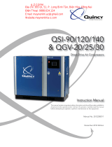
5.1 Principle of Compression
The stationary compressor package is fitted with a single stage, oil---injected airend. The
two rotors, the driven male rotor and the female rotor, both mounted in antifriction bear-
ings, are fitted into the airend. As the rotors rotate, air is drawn into the upper side through
the inlet port and is compressed on the lower side. The oil that is injected into the lower
side absorbs heat generated by compression, prevents metal to metal contact between
the rotors, seals the rotors and the housing from each other and also lubricates the antifric-
tion bearings. The compressed air and oil mixture leaves the airend via the discharge port.
12 3
4
6
5
1 Drive shaft 4 Male rotor
2 Oil injection 5 Female rotor
3 Discharge port 6 Air inlet port
5.2 Brief Description
The compressor block is driven by an electric motor via V---belts.
An oil separator cartridge is fitted into the oil separator tank allowing practically oil free
compressed air supply.
The control system of the compressor package ensures that compressed air is generated
within the set pressure limits.
Safety devices protect the compressor package against failure of important systems
through automatic shut---down.
The fan ensures ventilation of the compressor package and sufficient cooling air for the
air---cooled oil cooler and air aftercooler.
5.3 Pipe and Instrument Flow Diagram (P & I Diagram)
(see following pages)

Construction and Operation
5 --- 13

Construction and Operation
5 --- 14

Construction and Operation
5 --- 15
5.4 DUAL Control
p
max
p
min
Full load
Standstill
Motor power
Pressure
Time
t1 t2
12345
Idle
In DUAL Control (combined idle and start---stop) the compressor normally runs at full--
load, idle or standstill.
The controller regulates the compressor package between full--load and idle.
If the compressor package runs in idle for longer than the preset period (1) to (2), for
example t
1
= 6 min, the drive motor is stopped completely (2). When the lower switching
point p
min
(3) is reached the compressor package is automatically started again. Pressure
rises to the upper switching point p
max
(4), and the compressor package switches to idle. If
the pressure falls again to, for example, p
min
(5) within a shorter period (4) to (5), then the
compressor is automatically switched from idle to full---load.

Construction and Operation
5 --- 16
5.5 QUADRO Control
1
Full load
Standstill
Motor power Pressure
p
max
p
min
t
p
rise
t
p
decay
Running period
Idle/
standstill period
Run---on period
1111
Time
Stop point for the running period or idle / standstill period
132 24
p
max
upper switching point
p
min
lower switching point
t
p
rise
pressure rise time (the time during which the air system pressure rises
from the lower to the upper switching point)
t
p
decay
pressure decay time (the time during which the air system pressure decays
from the upper to the lower switching point)
4 511
Idle
Functional description
Two fixed periods --- the running period and idle/standstill period --- are taken as the crit-
erium for selection of the operating mode of the compressor package when the air mains
pressure reaches the upper switching point. These two periods are set according to the
maximum permissible cut---in frequency of the compressor motor.
The running period starts every time the compressor package is switched on. It lasts as
long as the compressor motor runs and stops when the compressor package switches to
full stop.
The idle/standstill period starts every time the operating mode changes from full load to off
load running. It runs during idle and also when the compressor package is switched to
standstill after the idle period. It stops when the compressor package switches to full load.
Every switching off point is delayed by the run---on period, during which time the com-
pressor package vents.
The following switching cycles are possible:
- If the air systems pressure decays to the lower switching point, the compressor pack-
age switches to full load (1) irrespective of its previous operating mode. If the com-
pressor motor was at a standstill the opening of the inlet valve is delayed to allow an
unloaded compressor package start.

Construction and Operation
5 --- 17
- If the air systems pressure rises to the upper switching point and the running period
has already expired, the compressor package is switched off after the run---on period
has expired (2).
- If the air systems pressure rises to the upper switching point before the running period
has expired then the pressure decay time of the previous switching cycle is taken as
the criterium for the selection of the operating mode:
-- If the pressure decay time t
p
decay
was longer than the period set for the idle/standstill
period, the compressor is switched to standstill after the run---on period has ex-
pired (3).
-- If the pressure decay time t
p
decay
was shorter than the period set for the idle / stand-
still period, the idle mode is selected (4), that is, the inlet valve closes and the com-
pressor is vented with running motor. When the running period expires the com-
pressor package switches to standstill only after the run---on period has also
expired (5).
5.6 VARIO Control
Functional description:
The idle period is automatically lengthened or shortened by the variable idle control in rela-
tion to the number of motor starts. The number of motor starts during the preceding hour
are measured.
A high switching frequency leads to longer idle periods.
A low switching frequency leads to shorter idle periods.
/