Page is loading ...

QSI-90/120/140
& QGV-20/25/30
Direct Drive Air Compressors
Instruction Manual
This manual contains important safety information and should be made available to
all personnel who operate and/or maintain this product. Carefully read this manual
before attempting to operate or perform maintenance on this equipment.
Manual No. 2012200011
December 2012 Edition
Địa chỉ: 365 QL 51, P. Long Bình Tân, Biên Hòa, Đồng Nai
Điện Thoại: 0888.624.124
Email: [email protected]
Website:maynenkhia-z.com
A-Z COPM


Table of Contents
Section I - General Information
Safety Alert Symbols ...........................................................................................................1
Safety Precautions ...............................................................................................................2
Spare Parts Ordering Information .......................................................................................3
Serial/Model Identification Plate .........................................................................................3
Section II - Description
General Description ............................................................................................................4
The Compression Cycle ......................................................................................................4
Air Flow ...............................................................................................................................5
Cooling System ...................................................................................................................5
Air-cooled Fluid Coolers ......................................................................................................5
Aftercoolers .........................................................................................................................5
Moisture Separ ator ..............................................................................................................5
Capacity Control System .....................................................................................................6
Controller Opt ions ...............................................................................................................6
Standard Control Lights, Indicators & Gauges ....................................................................7
Operating Mo des ................................................................................................................8
Electrical Syst em ..................................................................................................................9
Section III - Installation
Receiving ...........................................................................................................................10
Moving the Unit to the Installation Site .............................................................................10
Location .............................................................................................................................11
Shipping Suppo rts .............................................................................................................12
Piping Connections ...........................................................................................................12
Piping Fi t-up ......................................................................................................................12
Pressure V essels .................................................................................................................12
Relief V alves .......................................................................................................................13
Electrical ............................................................................................................................13
Pneumatic Circuit Breakers or Velocity Fuses ....................................................................14
Guards ...............................................................................................................................14
Manual Vent and Shutoff Valve ..........................................................................................14
Compressor R otation .........................................................................................................15
Fan Rotation ......................................................................................................................15
Section IV - Operating Procedures
Prior to Starting .................................................................................................................16
Starting the Compressor ...................................................................................................17
Stopping the Compressor .................................................................................................17
Emergency .........................................................................................................................17
QSI Standard Controls .......................................................................................................18

Table of Contents
Section V - Servicing
Preparing for Maintenance or Service ...............................................................................34
Safety ................................................................................................................................34
Maintenance Schedul e ......................................................................................................35
Maintenance & Troubleshooting .......................................................................................36
Water Removal ..................................................................................................................37
Air/Fluid Separator ............................................................................................................37
Air Fi lter .............................................................................................................................37
Shaft Seal ...........................................................................................................................38
Differential Pilot Valve .......................................................................................................40
Pressure Set ting .................................................................................................................40
Electronic Co ntrol ..............................................................................................................41
Air and Fluid Tubing ..........................................................................................................41
Water Co olers ....................................................................................................................43
Section VI - Compressor Fluids
Fluid Speci fications ............................................................................................................44
Lubrication .........................................................................................................................45
Fluid Level .........................................................................................................................45
Fluid Filter .........................................................................................................................46
Factors Affecting Fluid Life ................................................................................................46
Fluid Analysis Program - General ......................................................................................47
QuinSyn Plus .....................................................................................................................48
QuinSyn P G .......................................................................................................................49
QuinSyn X P ........................................................................................................................50
QuinSyn F ..........................................................................................................................51
QuinSyn Fl ush ....................................................................................................................51
Cleaning and Flushing With QuinSyn Flush ......................................................................52
Converting to QuinSyn PG ...............................................................................................53
Converting to QuinSyn XP ................................................................................................54
Converting to QuinSyn Plus ..............................................................................................55
Sampling P rocedures .........................................................................................................55
Understanding the Analysis Report ...................................................................................56
Fluid Parameters ...............................................................................................................58
Section VII - Troubleshooting
Troubleshooting ................................................................................................................60
Appendix A - Dimensional Drawings
QSI-90/120/140 ........................................................................................................... 66-73
QGV-20/25/30 ............................................................................................................ 74-77
Appendix B - Technical Data
QSI-90/120/140 ........................................................................................................... 78-80
QGV-20/25/30 ............................................................................................................ 81-83

Section I - General Information
Safety Alert Symbols•
Safety Precautions•
Spare Parts Ordering Information•
Serial/Model Identification Plate•
Safety Alert Symbols
WARNING!
This symbol identifies hazards or unsafe
practices which could result in personal
injury, death or substantial property
damage.
CAUTION!
Identifies hazards or unsafe practices
which could result in minor personal
injury or property damage.
NOTICE!
Identifies important installation,
operation or maintenance information
which is not hazard related.
IMPORTANT!
Throughout this manual we have identified key hazards. The following symbols identify
the level of hazard seriousness:
DANGER!
This symbol identifies immediate
hazards which will result in severe
personal injury, death or substantial
property damage.
DANGER!
This symbol identifies life threatening
electrical voltage levels which will result
in severe personal injury or death. All
electrical work must be performed by
a qualified electrician.
CAUTION!
This symbol identifies hot surfaces
which could result in personal injury or
property damage.
1

Section I - General Information
Safety Precautions
Read this manual and follow all instructions
prior to installing or operating the
compressor.
Listed below are some, but not all, safety
precautions that must be observed with
compressors and compressed air systems.
WARNING!
Failure to follow any of these precautions
may result in severe personal injury,
death, property damage and/or
compressor damage.
Air from this compressor will cause ♦
severe injury or death if used for
breathing or food processing. Air
used for these processes must
meet OSHA 29 CFR 1910.134 or
FDA21XDE178.3570 regulations.
Disconnect and lockout all power ♦
supplies to the compressor plus any
remote controllers prior to servicing the
unit.
Never assume it is safe to work on the ♦
compressor because it is not operating.
Many installations have automatic start/
stop controls and the compressor may
start at any time.
This compressor is designed for use in ♦
the compression of normal atmospheric
air only. No other gases, vapors or
fumes should be exposed to the
compressor intake, nor processed
through the compressor.
Relieve all pressure internal to the ♦
compressor prior to servicing. Do not
depend on check valves to hold system
pressure.
A properly sized pressure relief valve ♦
must be installed in the discharge
piping ahead (upstream) of any shutoff
valve (block valve), heat exchanger,
orifice or any potential blockage
point. Failure to install a pressure
relief valve could result in the rupturing
or explosion of some compressor
component.
Do not change the pressure setting of ♦
the pressure relief valve, restrict the
function of the pressure relief valve, or
replace the pressure relief valve with
a plug. Over pressurization of system
or compressor components can occur,
resulting in death, severe personal
injury or property damage.
Never use plastic pipe, rubber hose, ♦
or soldered joints in any part of the
compressed air system. Failure to
ensure system compatibility with
compressor piping is dangerous.
Never use a flammable or toxic solvent ♦
for cleaning the air filter or any parts.
Do not remove any guards or cabinet ♦
panels or attempt to service any
compressor part while the compressor
is operating.
Do not operate the compressor at ♦
pressures in excess of its rating.
Observe control panel displays daily ♦
to ensure compressor is operating
properly.
Follow all maintenance procedures and ♦
check all safety devices on schedule.
Never disconnect or tamper with the ♦
high air temperature (HAT) sensors.
Compressed air is dangerous, do not ♦
play with it.
2

Section I - General Information
Use the correct fluid at all times. ♦
Do not rely on the discharge air line ♦
check valve.
Do not override any safety or shutdown ♦
devices.
Keep the doors closed (on an enclosed ♦
unit) during operation and stay away
from an unenclosed compressor in
operation. The operating temperature
of some components is sufficient to
burn the skin.
NOTICE!
These instructions, precautions
and descriptions cover standard
Quincy manufactured QSI Series
air compressors. As a service to
our customers, we often modify or
construct packages to the customers
specifications. This manual may not be
appropriate in those cases.
NOTICE!
Every effort has been taken to ensure
complete and correct instructions have
been included in this manual, however,
possible product updates and changes
may have occurred since this printing.
Quincy Compressor® reserves the
right to change specifications without
incurring any obligation for equipment
previously or subsequently sold. Not
responsible for typographical errors.
Spare Parts Ordering Information
Quincy Compressor maintains replacement
parts for Quincy compressors and
accessories. A repair parts list is shipped
with all new machines. Order parts from
your Authorized Quincy distributor. Use
only genuine Quincy replacement parts.
Failure to do so may void warranty.
Serial/Model Identification Plate
Reference to the machine MODEL, SERIAL
NUMBER and DATE OF ORIGINAL START-
UP must be made in all communication
relative to parts orders. A model/serial
number plate is located on the frame or in
the upper right corner of the control panel
door.
3

Section II - Description
General Description•
The Compression Cycle•
Air Flow•
Cooling System•
Capacity Control System•
Controller Options•
Standard Control Lights, Indicators •
& Gauges
Operating Modes•
Electrical System•
General Description
The QSI line of rotary screw compressors
covers a horsepower range of 20 to 350
hp. These truly direct drive compressors
have standard full load pressure ratings
of 100, 125 and 150 PSIG. The large,
120/127mm rotors allow Quincy to operate
these compressors at lower speeds than
competitive makes.
The compressor is a single stage, positive
displacement, fl uid-fl ooded rotary screw
type unit, consisting of two precision-
machined rotors. The male rotor is driven
through a coupling arrangement.
All components are attached to a
heavy-duty steel frame. Controls and
indicators are arranged on a control panel.
Acoustical cabinets are standard on QSI
compressors. QSI-90, 120 and 140 units
are available mounted on a 120 gallon
receiver tank.
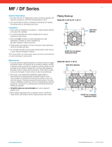
The Compression Cycle
The compression cycle of a rotary screw
compressor is a continuous process from
intake to discharge with no reciprocating
mechanisms starting and stopping as
found in reciprocating compressors. The
compressor consists of two rotors in
constant mesh, housed in a cylinder with
two parallel adjoining bores. The male
drive rotor has four or fi ve lobes that mesh
with six fl utes in the female rotor. All parts
are machined to exacting tolerances.
As the rotors rotate, (male-clockwise as
viewed from the power input end) air is
drawn into the cylinder through the inlet
port located at the power input end. A
volume of air is trapped as the rotor lobes
pass the inlet cut off points in the cylinders.
Compression occurs as the male rotor
rolls into the female fl ute, progressively
reducing the space thereby raising the
pressure. Compression continues until
the lobe and fl ute pass the discharge port.
The compressed air is then discharged into
the air/fl uid reservoir. There are four or
fi ve complete compression cycles for each
complete rotation of the male rotor.
INLET PORT CYLINDER
MALE
ROTOR
FEMALE ROTOR DISCHARGE PORT
Compression Cycle
A) INTAKE B) COMPRESSION C) DISCHARGE
4

Section II - Description
Air Flow
When the compressor is operating,
a partial vacuum is produced at the
compressor inlet. Air entering via the air
fi lter fl ows through the inlet valve into
the rotor housing where it is compressed,
then discharged into the air/fl uid reservoir.
Compressed air passes through the air/
fl uid separator, then through a minimum
pressure check valve, through the
aftercooler and moisture trap to the service
connection.
Cooling System
Air-cooled Fluid Coolers
The air-cooled fl uid cooler and aftercooler
are fi nned aluminum plate design. QSI-
90, 120 and 140 models use a one-piece
combination cooler/aftercooler. Ambient
air is induced through the fi ns by a
centrifugal fan, cooling the fl uid and air in
the plates. To maintain proper compressor
operation, the ambient air temperature
should not exceed the temperatures listed
in Appendix B - Technical Data. The cooler
fi ns must be kept clean at all times. Fluid
leaving the receiver passes through a
thermal mixing valve before traveling on
to the cooler. The purpose of the thermal
valve is to maintain a minimum fl uid
discharge temperature at the compressor
of approximately 190°F.
Aftercoolers
Aftercoolers reduce the amount of water
in the discharge air. They are used to
lower the temperature of the discharge
air thereby condensing water vapor from
the compressed air. This allows most of
the contained water to be trapped and
expelled from the unit, reducing water
related problems downstream.
Moisture Separator
A combination moisture separator and
water trap is provided for collecting and
expelling water to the customer’s drain.
5

Section II - Description
Capacity Control System
As the motor starts driving the compressor
rotors, air is drawn in, compressed and
discharged into the system downstream.
When the air pressure at the service
connection exceeds the set point of the
pilot valve (normally 100 PSIG), it begins to
close the air supply off to the unloader.
The air forces a piston to move within
the cylinder, closing the inlet valve. The
compressor will continue to run, matching
air demand with air delivery by constantly
adjusting the position of the inlet valve.
The inlet valve regulates compressor
capacity between 100% and nearly 0% of
rated delivery.
When maximum pressure (typically 15
PSIG above normal full load pressure)
has been obtained in the air system,
complete compressor unloading occurs.
The pressure switch Or transducer sends
a signal to the control and the solenoid
valve opens, venting the residual pressure
through the blowdown valve.
Controller Options
Standard QSI compressors are equipped
with either an electronic controller with
an HMI control panel which utilizes a
microprocessor to control the compressor
or standard controls with a auto dual
operating mode and lights, indicators
and gauges for monitoring compressor
operation.
6

Section II - Description
Standard Control Lights, Indicators &
Gauges
Main Power on Light
Indicates when power from the main
disconnect switch has been turned on
and there is live power at the compressor
starter and control panel. This light will
remain on as long as there is power to the
unit, regardless of the position of the auto
dual switch.
CAUTION!
Always check power supply
disconnect. The power on light may
be inoperable.
High Discharge Air Temperature Light
Indicates when the unit has sensed an
unusually high discharge temperature.
Hourmeter
Indicates actual hours of operation on the
compressor.
Air Pressure Gauge
This gauge indicates air pressure available
for distribution to the service line.
CAUTION!
Gauge may not register when the unit
is unloaded or off. Make certain all air
pressure is relieved prior to servicing.
Percent Capacity Gauge
This gauge is graduated in percent of the
total capacity of the unit. Readings taken
from this gauge give an indication of the
amount of air being used.
Discharge Temperature Gauge
This gauge indicates the temperature of
the air/fl uid mixture as it discharges from
the compressor. The normal reading is 180-
200°F.
7

Section II - Description
Operating Modes
WARNING!
Never assume it is safe to work on a
compressor because it is not operating.
It may be in standby mode and could
restart at any time. Follow all safety
instructions in Section V - Maintenance
or Service Preparation.
Load/No Load
In the Load/No Load mode, the
compressor does not modulate the inlet
valve. The valve is either fully open or it is
closed. If system demands include regular
periods of air usage at less than full load,
a large compressed air storage capability
is required with this type of control.
Without adequate storage, rapid cycling
may occur. This will cause wide system
pressure fl uctuations that may affect the
performance of equipment using the
compressed air. Load/No Load works with
Auto Dual control to turn the compressor
off during extended periods of no demand.
8

Section II - Description
Electrical System
Electrical system diagrams are shown in
the parts manual sent with the compressor.
The appropriate diagram is also included
in the control panel on all Quincy QSI
compressors.
NOTICE!
Due to continuous product
improvements and updates, it is
suggested that the wiring diagram
included in the control panel be used
when servicing the electrical control.
Standard QSI drive motors are open, drip
proof (ODP), 3600 RPM motors with a
maximum ambient temperature rating of
104°F (40°C).
QSI series compressors utilize 460V
incoming power through a full voltage
(across the line) starter. A dual output
transformer in the control panel reduces
the voltage to 120 VAC for the various
controls on the unit. These controls
include the PLC, HMI, high air temperature
safety switch and solenoid. Other
incoming line voltages and a wye-delta
starter are available as options. The
compressor is provided with a NEMA 4
enclosure.
DANGER!
High voltage could cause death or
serious injury. Disconnect all power
supplies before opening or servicing
the electrical enclosure.
High Air Temperature Switch
A high air temperature (HAT) switch
is standard on QSI units. The HAT is
located on the air/fl uid reservoir and
protects the unit by sensing unusually high
temperatures and shutting the unit down.
The HAT is set to trip at approximately
235°F and is nonadjustable.
WARNING!
Never remove, bypass or tamper with
the HAT switch. Failure to provide this
safety feature could cause death or
serious injury and property damage. If
the compressor is shutting down due to
high temperature, contact a qualified
service technician immediately.
9

Section III - Installation
Receiving•
Moving the Unit to the Installation •
Site
Location•
Shipping Supports•
Piping Connections•
Pressure Vessels•
Relief Valves•
Electrical•
Pneumatic Circuit Breakers or •
Velocity Fuses
Guards•
Manual Vent and Shutoff Valves•
Compressor Rotation•
Fan Rotation•
Receiving
Upon receipt, immediately inspect the
compressor for any visible damage that
may have occurred during shipment. If
visible damage is found, the delivering
carrier must make a notation on the
freight bill and the customer should
request a damage report. If the shipment
is accepted and damage is found later,
it is classifi ed as concealed damage.
Concealed damage should be reported
to the delivering carrier within 15 days
of delivery. The delivering carrier must
prepare a damage report. Itemized
supporting papers are essential to fi ling a
claim.
Read the compressor nameplate to be
sure the compressor is the model and size
ordered and that optionally ordered items
are included.
Check the reservoir and pressure relief
valves to be sure they are adequate for the
pressure at which you intend to operate.
Moving the Unit to the Installation Site
Forklift slots are provided on both sides of
the main frame. Use of chains and slings
should be limited to the main frame. Do
not attempt to lift the unit by attaching to
any components. Optional lifting eyes are
available.
NOTICE!
See Appendix A and B for detailed
technical information and dimensions.
CAUTION!
Improper lifting may result in component,
system damage or personal injury.
Follow good shop practices and safety
procedures when moving the unit.
10

Section III - Installation
Location
Locate the compressor on a level surface
in a clean, well-lit and well-ventilated
area. Allow suffi cient space (four feet
of clearance on all sides and top of
the compressor) for safe and proper
daily inspection and maintenance. The
entire length of the frame base must be
supported. Shim where necessary but do
not use wood.
WARNING!
Under no circumstances should a
compressor be installed in an area
exposed to a toxic, volatile or corrosive
atmosphere, nor should toxic, volatile
or corrosive agents be stored near the
compressor.
Ambient temperature should not exceed
110°F. High ambient temperatures may
result in a high air temperature shutdown.
All models are intended for indoor
installation, however, it is possible, with
certain modifi cations, to accommodate
some outdoor locations. Cabinet models
are water-resistant but not water tight.
Sheltering from rain, snow and freezing
temperatures is mandatory.
WARNING!
Do not operate in temperatures below
34°F or above the limits outlined in
Appendix B - Technical Data.
Do not locate the unit where the hot
exhaust air from other compressors or heat
generating equipment may be drawn into
the unit. Never restrict the fl ow of exhaust
air from the fl uid cooler or cooling fan.
Heated exhaust air must be exhausted
outside to prevent high temperature
conditions in the compressor room. If
the room is not properly ventilated,
compressor operating temperatures will
increase and cause a high temperature
shutdown.
CAUTION!
Clean, fresh air, of sufficient quantity,
is required for proper compressor
operation.
In high humidity areas, avoid placing
the compressor in a basement or other
damp locations. Control the compressor
temperatures and monitor compressor fl uid
for signs of water contamination. Fluid and
fi lter changes may need to be increased,
and/or fl uid may need to be changed to
QuinSyn-PG in high humidity areas.
Quincy QSI compressors are essentially
vibration free, however, some customers
may choose to bolt the unit to the fl oor
to prevent the accidental breakage of
piping or electrical connections as a result
of being bumped. Use only lag bolts to
secure the unit. Do not pull the bolts down
tight. Overtightening the lag bolts may
place the frame in a twist or bind causing
breakage of fl uid coolers, piping and
reservoirs.
WARNING!
Removal or painting over safety labels
will result in uninformed conditions.
This could result in personal injury or
property damage. Warning signs and
labels shall be provided with enough
light to read, conspicuously located
and maintained for legibility. Do
not remove any warning, caution or
instructional material attached.
11

Section III - Installation
Shipping Supports
Shipping supports are used to secure
the motor and airend during shipping to
prevent damage to the motor, airend,
reservoir and the connections to these
components.
The shipping supports are painted red and
are located near the motor support.
NOTICE!
Once the compressor has been located
and secured at the installation site, the
shipping supports must be removed
before operating the unit.
To remove the shipping supports, remove
the screws attaching them to the airend
and to the base.
Piping Connections
Never join pipes or fi ttings by soldering.
Lead-tin solders have low strength, a
low creep limit, and may, depending on
the alloy, start melting at 360°F. Silver
soldering and hard soldering are forms of
brazing and should not be confused with
lead-tin soldering. Never use plastic, PVC,
ABS pipe or rubber hose in a compressed
air system.
Piping Fit-up
Care must be taken to avoid assembling
the piping in a strain with the compressor.
Piping should line up without having
to be sprung or twisted into position.
Adequate expansion loops or bends
should be installed to prevent undue
stress at the compressor resulting from the
changes between hot and cold conditions.
Pipe supports should be mounted
independently of the compressor and
anchored, as necessary, to limit vibration
and prevent expansion strains. Piping
should never be of smaller size than the
connection on the compressor unit.
Pressure Vessels
Air receiver tanks should be in accordance
with ASME Boiler and Pressure Vessel
Code Section VIII. CAUTION!
ASME coded pressure vessels must
not be modified, welded, repaired,
reworked or subjected to operating
conditions outside the nameplate
ratings. Such actions will negate code
status, affect insurance status and
may cause death, serious injury and
property damage.
12

Section III - Installation
Relief Valves
Pressure relief valves are sized
to protect the system. Never
change the pressure setting or
tamper with the valve. Only
the relief valve manufacturer
or an approved representative
is qualifi ed to make such a
change.
DANGER!
Relief valves are to protect system
integrity in accordance with ANSI/
ASME B19 safety standards. Failure
to provide properly sized relief valves
could result in death or serious injury.
Electrical
Before installation, the electrical supply
should be checked for adequate wire size
and capacity. During installation, a suitable
fused disconnect switch or circuit breaker
should be provided. Any unreasonable
voltage unbalance (5%) between the legs
must be eliminated and any low voltage
corrected to prevent excessive current
draw. The installation, electric motor,
wiring and all electrical controls must
be in accordance with National Electric
Code, and all state and local codes. A
qualifi ed electrician should perform all
electrical work. Air compressors must be
grounded in accordance with applicable
codes. See control panel for the proper
wiring diagram.
Quincy would like to emphasize the
importance of providing adequate
grounding for air compressors. The
common practice of grounding units to
building structural steel may not actually
provide adequate grounding protection, as
paint and corrosion buildup may exist.
CAUTION!
NEMA electrical enclosures and
components must be appropriate to
the area in which they are installed.
Relief valves are to be placed ahead of
any potential blockage point that includes,
but is not limited to, such components
as shutoff valves, heat exchangers and
discharge silencers. Ideally, the relief
valve should be threaded directly into the
pressure point it is sensing, not connected
with tubing or pipe and pointed away from
any personnel. Always direct discharge
from relief valves to a safe area away from
personnel.
13

Section III - Installation
Pneumatic Circuit Breakers or Velocity
Fuses
Pneumatic safety devices are designed to
prevent hoses from whipping, which could
result in a serious or fatal accident.
The Occupational Safety and Health Act,
Section 1926.303 Paragraph 7 published
in Code of Federal Regulations 29 CFR
1920.1 (revised 07/01/1982), states “all
hoses exceeding 1/2” inside diameter
shall have a safety device at the source of
supply or branch line to reduce pressure in
case of a hose failure.”
Guards
All mechanical action or motion is
hazardous in varying degrees and needs to
be guarded. Guarding shall comply with
OSHA Safety and Health Standards 29 CFR
1910.219 in OSHA manual 2206 (revised
11/07/1978) and any state or local codes.
WARNING!
Cabinet panels and drive guards must
be fastened in place before starting
the machine and never removed before
lock out/tag out of the main power
supply.
Manual Vent and Shutoff Valve
Install a manual valve to vent the
compressor and the compressor discharge
line to atmosphere. If the air receiver tank
services a single compressor, the manual
valve can be installed in the receiver.
When a manual shutoff valve (block valve)
is used, a manual valve should be installed
upstream from the valve, and a pressure
relief valve installed upstream from the
manual vent valve. These valves are
to be designed and installed to permit
maintenance to be performed in a safe
manner. Never substitute a check valve for
a manual shutoff valve (block valve) if the
purpose is to isolate the compressor from a
system for servicing.
WARNING!
Relieve compressor and system air
pressure by opening the appropriate
manual relief valve prior to servicing.
Failure to relieve all system pressure
could result in death or serious injury
and property damage.
14

Section III - Installation
Compressor Rotation
Compressor rotation must be checked
prior to start-up. Proper rotation is
clockwise (as viewed from the power-
input end). The power-input end of the
compressor is marked with an arrow
noting the proper rotation. Operating the
compressor in incorrect rotation will result
in extreme damage to the compressor
and warranty coverage will be voided. To
check for proper rotation, jog the starter
button, allowing the motor to turn 2 or 3
revolutions. Observe the drive element
for correct direction. If incorrect rotation is
observed, lock out power supply, reverse
electrical leads L1 and L3 at the motor
starter. Recheck for correct rotation.
Alternate method to check rotation is to
remove drive coupling element prior to
bump starting the motor.
Fan Rotation
QSI compressors use a centrifugal fan.Fan
rotation is checked making sure the fan
ratation matches the arrow decal. The fan
must rotate in the direction indicated by
the arrow.
NOTICE!
Never assume the fan rotation
is correct based on the induced
air flow across the coolers. A
centrifugal fan can pull the airflow
across the coolers when rotating
in either direction, however,
incorrect rotation will cause a
high discharge temperature.
15

Section IV - Operating Procedures
Prior to Starting•
Starting the Compressor•
Stopping the Compressor •
HMI Control Panel Operation•
Prior to Starting
CAUTION!
Provisions should be made to have the
instruction manual readily available
to the operator and maintenance
personnel. If, for any reason, any parts
of the manual become illegible or if
the manual is lost, have it replaced
immediately. The instruction manual
should be read periodically to refresh
one’s memory. This may prevent a
serious accident.
Before starting the compressor, review
Sections II and III of this manual. Be certain
that all installation requirements have
been met and that the purpose and use of
the controls are thoroughly understood.
Before placing the compressor into
operation, do the following:
Remove all loose items and tools from ♦
around the compressor.
Check fluid level in the air/fluid ♦
reservoir. See Compressor Fluid
Section.
Check the fan and fan mounting for ♦
tightness.
Manually rotate the compressor ♦
through enough revolutions to be
certain there are no mechanical
interferences.
Check all pressure connections for ♦
tightness.
Check to make sure all relief valves are ♦
in place.
Check to make sure all panels and ♦
guards are in place and securely
mounted.
Check fuses, circuit breakers and ♦
thermal overloads for proper size.
Close the main power disconnect ♦
switch and jog the starter switch button
to check the rotational direction of the
compressor.
Check the fan rotation. ♦
Remove the red shipping brackets. ♦
16
/