Page is loading ...

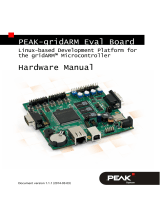
Evaluation Board User Guide
UG-649
One
Technology
Way
•
P.O.
Box
9106
•
Norwood,
MA
02062-9106,
U.S.A.
•
Tel:
781.329.4700
•
Fax:
781.461.3113
•
www.analog.com
Advantiv EVAL-ADV8005-SMZ Video Evaluation Board
PLEASE SEE THE LAST PAGE FOR AN IMPORTANT
WARNING AND LEGAL TERMS AND CONDITIONS.
Rev. PrB | Page 1 of 9
FEATURES
Primary Inputs: 1 HDMI (HDCP)
Secondary Inputs: 1 HDMI (HDCP)
(the board also includes VGA input and Component input
but these are not currently supported by the SW driver)
Outputs: 1 HDMI
ADDITIONAL EQUIPMENT/SOFTWARE NEEDED
Computer with RS-232 I/O for:
Sending commands to the software driver and viewing
debug messages from the software driver
Reading/writing registers using the AVES3 application for
Windows (requires Windows 7 or higher)
Updating the software driver (if desired or necessary)
GENERAL DESCRIPTION
The Advantiv® EVAL-ADV8005-SMZ video evaluation board
(AVEB) is a low cost solution for evaluating the performance of
the ADV8005 video signal processor.
The evaluation board provides a Blackfin® ADSP-BF524 processor
for system control and includes a software driver (firmware)
that provides a serial command interface to control the board's
functionality.
This evaluation board includes High-bandwidth Digital
Content Protection (HDCP) technology and is only available
to licensees of HDCP.
PHOTOGRAPH OF EVALUATION BOARD
Figure 1. Advantiv EVAL-ADV8005-SMZ Video Evaluation Board

UG-649 Evaluation Board User Guide
Rev. PrB | Page 2 of 9
TABLE OF CONTENTS
Features .............................................................................................. 1
Additional Equipment/Software Needed ...................................... 1
General Description ......................................................................... 1
Photograph of Evaluation Board .................................................... 1
Revision History ............................................................................... 2
Terminology ...................................................................................... 4
Evaluation Board Hardware ............................................................ 5
Configuring The Evaluation Board ............................................6
Evaluation Board Software ...............................................................7
Upgrading the Application binary using u-boot .......................7
Upgrading the OSD binary using u-boot...................................8
Evaluation Board Artwork and Components ................................9
Related Links ..................................................................................9
REVISION HISTORY

Evaluation Board User Guide UG-649
Rev. PrB | Page 3 of 9

UG-649 Evaluation Board User Guide
Rev. PrB | Page 4 of 9
TERMINOLOGY
Throughout this user guide, the following terms are used.
Source
A source outputs digital audio/video over a DVI/HDMI
interface. This can be a DVD/Blu-ray player, set-top box, game
console, or any other device with a DVI/HDMI output.
Sink
A sink accepts video through a DVI/HDMI interface. This is
nearly always a display with DVI/HDMI input in the context of
this user guide.
Software driver
"Software driver" refers to the software that runs on the ADSP-
BF524 and implements the link between a source and sink with
respect to this evaluation board.

Evaluation Board User Guide UG-649
Rev. PrB | Page 5 of 9
EVALUATION BOARD HARDWARE
A block diagram of the EVAL-ADV8005-SMZ is shown in Figure 2 and components are described in Table 1:
DIGITAL
AUDIO
VIDEO
ANALOG OUTPUTS
HDMI INPUT
ADV7625
SDRAM
MEMORY
HDMI
DIGITAL
AUDIO
VIDEO
DIGITAL
AUDIO
VIDEO
HEADER
FOR TTL
INPUT
ANALOG INPUTS
HDMI INPUT
HDMI CONNECTOR
BF524
BLACKFIN
CPU
ADV8005
ADV7842
FPGA
I2C
DIGITAL
AUDIO
VIDEO
HEADER
FOR TTL
OUTPUT
IR
RECEIVER
SDRAM
MEMORY
JTAG
RS232
PUSH
BUTTONS
HDMI CONNECTOR
FLASH
MEMORY
Figure 2. Block Diagram of the EVAL-ADV8005-SMZ
Table 1. Evaluation Board Hardware Components
Reference
Designator
Function Description
JT2 Power Connector J12 is where the 7.5 V, 4 A power supply is connected.
SWT8 BF524 Reset This switch resets the BF524 processor.
PT1 BF524 RS-232 port RS-232 interface between the BF524 and the computer (for user control and debug output).
PT2 BF524 USB port USB interface between the BF524 and the computer (will be used in future to update OSD)
JT10 BF524 JTAG The ICE-100B or the HPUSB-ICE is connected here to program the BF524 flash or to execute source code
debugging.
JT11 HDMI Input HDMI Input for the ADV7625 (This is the primary video input on the SW driver that is shipped with this board)
JT12 HDMI Input HDMI Input for the ADV7842 (used for picture-in-picture on the SW driver that is shipped with this board)
JT13 Component Input Component input for the ADV7842 (used for picture-in-picture on the SW driver that is shipped with this
board)
JT14 Graphics Input Graphics (RGB) input for the ADV7842 (used for picture-in-picture on the SW driver that is shipped with this
board)
JT4 HDMI Output HDMI Output (TX1) from the ADV8005
JT6 Dig A/V Input Header for Digital Audio/Video Input (TTL)
JT3 Dig A/V Output Header for Digital Audio/Video Output (TTL)

UG-649 Evaluation Board User Guide
Rev. PrB | Page 6 of 9
CONFIGURING THE EVALUATION BOARD
Whereas in the past, we provided scripts to configure our evaluation boards, due to the flexibility of the ADV8003, we strongly
recommend using the software driver to configure the board and evaluate the components.
Whether the software driver starts automatically depends on if a jumper is installed across Pin 1 and Pin 2 of JT7, as follows:
* If a jumper is not installed on JT7 pins 1-2, the application will automatically start the software driver after power-up or reset. At that point
the board can be configured using the console commands (or in a limited manner by the supplied infrared remote control)
* If jumper is installed on JT7 pins 1-2, the application will pause at the command prompt and not start the software driver in order to
allow the user to configure the board. The user would probably only do this if they wanted to experiment with configuring the board with
an external microprocessor.
The RS-232 command-line interface operates at 115,200 baud, eight data bits, no parity, one stop bit, and no flow control. Typing help via
RS-232 lists the commands that can be used to control the board as well as indicate the version of firmware and build date.
The SW driver is a collection of routines that configures the various devices via I2C. The RS232 output is used to provide useful
information back to the user. Registers can still be read/written from the command line, but anything that is written to a register can be
overwritten by the SW driver.
Since the commands for the software driver change frequently, we describe these in a separate document available in the EVAL-
ADV8005-SMZ support page on EngineerZone (https://ez.analog.com/docs/DOC-11128).
AVES3
AVES3 is a Windows®-based application that runs on a PC and allows the user to read and write registers on the ADV7842, ADV7625,
and ADV8005. It also displays the individual bit fields for each register and allows the user to read/write these individual bit fields. The
software supports RS-232, USB, and I
2
C (using the Total Phase Aardvark I
2
C/SPI host adapter).
Starting with AVES3, each evaluation board will have its own AVES3 folder which will contain files specific to that evaluation board.
The AVES3 folder for this board can be downloaded from the EVAL-ADV8005-SMZ support page on EngineerZone
(https://ez.analog.com/docs/DOC-11128).

Evaluation Board User Guide UG-649
Rev. PrB | Page 7 of 9
EVALUATION BOARD SOFTWARE
The SW driver on evaluation board can be updated using the u-boot bootloader that comes with board. However, we suggest that
customers purchase VisualDSP++ 5.0 and a low-cost JTAG debugger for Blackfin processors (HPUSB-ICE or ICE-100B) to use in case
the u-boot software is accidentally erased or corrupted.
UPGRADING THE APPLICATION BINARY USING U-BOOT
Every EVAL-ADV8005-SMZ evaluation board ships with the U-Boot boot loader firmware. Assuming this software hasn't been
erased/corrupted, you have the option of upgrading the firmware using only an RS-232 cable and software.
The output from u-boot should look something like this:
-------------------
U-Boot 2012.07-rc2 (ADI-2012R2) (Jul 16 2013 - 11:21:16)
CPU: ADSP bf524-0.2 (Detected Rev: 0.2) (spi flash boot)
Board: ADI Advantiv™ Video Evaluation Board
Support: http://ez.analog.com
Clock: VCO: 300 MHz, Core: 300 MHz, System: 100 MHz
RAM: 8 MiB
SF: Detected M25P32 with page size 64 KiB, total 4 MiB
In: serial
Out: serial
Err: serial
KGDB: [on serial] ready
Hit any key to stop autoboot:
-------------------
If you see this RS232 output, you can use the following steps to upgrade the application binary on your board (if you determine this is
necessary). Note that these instructions assume you are using the version 4.78 of Tera Term for Windows (which is free to download and
use). We have experienced YMODEM issues with previous versions of TeraTerm, so we strongly suggest using version 4.78 or higher.
1. After you see the hit any key to stop autoboot prompt, press a key during the countdown. You should then see a prompt, bfin >.
2. At the prompt, type the following command:
sf probe 0:1
You should see the following:
SF: Detected M25P32 with page size 64 KiB, total 4 MiB
bfin>
3. At the prompt, type the following command:
loady
You should see the following output:
## Ready for binary (ymodem) download to 0x00800000 at 115200 bps...
4. In Tera Term, under File, click Transfer, then YMODEM, and select Send…
5. Select the application binary file (for example, BF_7625_8005_VSP_1.80_RC3_20140321.bin) and click Open.
You should see the YMODEM send dialog box progress quickly from 0% to 100%. If the software stalls at Packet 1 or Packet 2 for a few
seconds, you may need to cancel and retry. It is possible that you may need to repeat Step 3 through Step 5 a few times to accomplish the
transfer. After the transfer is complete, you should see something like the following output:
CCxyzModem - CRC mode, 0(SOH)/721(STX)/0(CAN) packets, 4 retries
## Total Size = 0x000b3f70 = 737136 Bytes
bfin>
6. At the prompt, type the following command to erase the application area of the SPI flash memory:
sf erase 0x60000 0xc0000
(Note: that this is slightly larger than the value 0xa0000 used on previous evaluation boards)
You should then see the following output:
bfin>
7. At the prompt, type the following command to program the application area of the SPI flash memory:
sf write $(loadaddr) 0x60000 $(filesize)
You should then see the following output:
bfin>
8. At this point, if you reset your board and allow the countdown to complete, U-Boot should launch the application binary that you just
programmed.

UG-649 Evaluation Board User Guide
Rev. PrB | Page 8 of 9
UPGRADING THE OSD BINARY USING U-BOOT
u-boot can also be used to program the OSD binary (located in UT27). You can use the following steps to upgrade the OSD binary on
your board (if you determine this is necessary). Note that these instructions assume you are using version 4.78 of Tera Term for Windows
(which is free to download and use). Note: we have experienced YMODEM issues with previous versions of TeraTerm, so we strongly
suggest using version 4.78 or higher.
1. At the bfin> prompt, type the following command:
run spiloopon
2. You should see the following output:
gpio: pin pg9 (gpio 25) value is 1
gpio: pin pf5 (gpio 5) value is 0
gpio: pin pf7 (gpio 7) value is 1
3. Type the following command:
sf probe 0:3
4. You should see the following output:
SF: Detected M25P128 with page size 256 KiB, total 16 MiB
bfin>
( Note: you may need to enter this command 2-3 times in order to detect the M25P128 correctly.)
At the prompt, type the following command:
loady
You should see the following output:
## Ready for binary (ymodem) download to 0x00800000 at 115200 bps...
1. In Tera Term, under File, click Transfer, then YMODEM, and select Send…
2. Select the OSD binary file (for example, OSD_1.80RC3_20140312.bin) and click Open.
3. You should see the YMODEM send dialog box progress slowly from 0% to 100%. If the software stalls at Packet 1 or Packet 2 for a
few seconds, you may need upgrade Teraterm to version 4.78. (Note: we have noticed that if the software stalls, it typically results in a
wrong file size. We believe this was an issue with YMODEM transfer in Teraterm and the version 4.78 appears to have fixed it.)
4. After the transfer is complete, you should see something similar to the following output:
CCxyzModem - CRC mode, 0(SOH)/7739(STX)/0(CAN) packets, 3 retries
## Total Size = 0x0078e6e5 = 7923429 Bytes
5. bfin>At the prompt, type the following command to erase the contents of UT27 (serial flash memory for ADV8005 OSD)
sf erase 0x0 0x800000
You should then see the following output:
bfin>
6. At the prompt, type the following command to program UT27 with the OSD binary
sf write $(loadaddr) 0x0 $(filesize)
You should then see the following output:
bfin>

Evaluation Board User Guide UG-649
Rev. PrB | Page 9 of 9
EVALUATION BOARD ARTWORK AND COMPONENTS
Figure 3. Assembly Drawing (Top Side) of the EVAL-ADV8005-SMZ
RELATED LINKS
Resource Description
TBD TBD
I
2
C refers to a communications protocol originally developed by Philips Semiconductors (now NXP Semiconductors).
/