Page is loading ...

Quattro
®
AC/PM
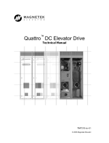
Quattro AC/PM Elevator Drive
Technical Manual
To properly use the product, read this manual thoroughly and retain for easy reference, inspection,
and maintenance. Ensure that the end user receives this manual.
TM7341 Rev 11
© Magnetek Elevator 2019

WARRANTY Standard products manufactured by the Company are warranted to be free from
defects in workmanship and material for a period of one year from the date of
shipment, and any products which are defective in workmanship or material will be
repaired or replaced, at the Company’s option, at no charge to the Buyer. Final
determination as to whether a product is actually defective rests with the Company.
The obligation of the Company hereunder shall be limited solely to repair or replace,
at the Company’s discretion, products that fall within the foregoing limitations, and
shall be conditioned upon receipt by the Company of written notice of any alleged
defects or deficiency promptly after discovery and within the warranty period, and in
the case of components or units purchased by the Company, the obligation of the
Company shall not exceed the settlement that the Company is able to obtain from the
supplier thereof. No products shall be returned to the Company without its prior
consent. Products which the company consents to have returned shall be shipped
prepaid f.o.b. the Company factory. The Company cannot assume responsibility or
accept invoices for unauthorized repairs to its components, even though defective.
The life of the products the Company depends, to a large extent, upon type of usage
thereof and THE COMPANY MAKES NO WARRANTY AS TO FITNESS OF ITS
PRODUCTS FOR THE SPECIFIC APPLICATIONS BY THE BUYER NOR AS TO
PERIOD OF SERVICE UNLESS THE COMPANY SPECIFICALLY AGREES
OTHERWISE IN WRITING AFTER PROPOSED USAGE HAS BEEN MADE KNOWN
TO IT.
This warranty does not apply to experimental products for which no warranty is made
or given and Buyer waives any claim thereto.
THE FOREGOING WARRANTY IS EXCLUSIVE AND IN LIEU OF ALL OTHER
WARRANTIES, EXPRESSED OR IMPLIED, INCLUDING, BUT LIMITED TO, ANY
WARRANTY OF MECHANTIBILITY OR OF FITNESS FOR A PARTICULAR
PURPOSE AND BUYER HEREBY WAIVES ANY AND ALL CLAIMS THEREFORE.
LIMITATIONS IN NO EVENT SHALL MAGNETEK BE LIABLE FOR LOSS OF PROFIT,
OF LIABILITY INDIRECT, CONSEQUENTIAL OR INCIDENTAL DAMAGES WHETHER
ARISING OUT OF WARRANTY, BREACH OF CONTRACT OR TORT.
QUATTRO is a trademark of Magnetek, Inc.
All rights reserved. No part of this publication may be reproduced or used in any form or by any means - graphic, electronic, or
mechanical including photocopying, recording, taping, or information storage and retrieval systems - without written permission
of the publisher.
© 2019 Magnetek, Inc.

1
TM7341 Rev 11
Table of Contents
Drive Model Numbers (Cube) .............................................................................................................. 6
Drive Model Numbers (Enclosed) ........................................................................................................ 7
Introduction .......................................................................................................................................... 20
Drive Ratings and Specifications ....................................................................................................... 20
Quattro Startup Guide ......................................................................................................................... 21
Initial Inspection ................................................................................................................................. 21
Grounding considerations .................................................................................................................. 22
Initial adjustments after power up ...................................................................................................... 22
Interconnections .................................................................................................................................. 24
Logic Inputs ........................................................................................................................................ 28
Analog Inputs ..................................................................................................................................... 28
Logic Outputs ..................................................................................................................................... 29
Relay Outputs .................................................................................................................................... 30
Solid State Relay Outputs .................................................................................................................. 30
Analog Outputs .................................................................................................................................. 30
Encoder Connections ......................................................................................................................... 31
Drive Sequencing ................................................................................................................................ 33
NORMAL operating sequence ........................................................................................................... 33
ABNORMAL Operation Sequence ..................................................................................................... 34
Quattro AC/PM Pre-Charge ............................................................................................................... 34
Drive Operation and Feature Overview ............................................................................................. 35
Analog Velocity Follower .................................................................................................................... 35
Preset Speed & Profile Generator ..................................................................................................... 35
Serial Link Follower ............................................................................................................................ 35
Pre-Torque ......................................................................................................................................... 35
Torque Feed Forward ........................................................................................................................ 35
Torque/Current Ramp-Down .............................................................................................................. 35
DSPR ................................................................................................................................................. 36
Over-Speed Test ................................................................................................................................ 36
Fault & Alarm Reset ........................................................................................................................... 36
Electronic Motor Over-Load ............................................................................................................... 36
MONITOR / Adjust / Set-up Parameters: ........................................................................................... 36
Parameters ........................................................................................................................................... 37
Parameter Introduction ....................................................................................................................... 37
Adjust A0 menu ................................................................................................................................... 39
Drive A1 submenu .............................................................................................................................. 39
Multistep Ref A3 submenu ................................................................................................................. 56
Motor Side Power Converter A4 submenu ........................................................................................ 58
Line Side Power Converter A5 submenu ........................................................................................... 62
Motor A6 submenu ............................................................................................................................. 64
Configure C0 menu ............................................................................................................................. 70
User Switches C1 submenu ............................................................................................................... 70
Logic Inputs C2 submenu .................................................................................................................. 87

TM7341 Rev 11
2
Logic Outputs C3 submenu................................................................................................................ 90
Analog Outputs C4 submenu ............................................................................................................. 92
Display D0 menu .................................................................................................................................. 94
Elevator Data D1 submenu ................................................................................................................ 94
MS Power Data D2 submenu............................................................................................................. 97
LS Power Data D3 submenu.............................................................................................................. 99
Utility U0 menu .................................................................................................................................. 100
Fault F0 menu .................................................................................................................................... 107
Maintenance ....................................................................................................................................... 109
Maintenance Overview ..................................................................................................................... 109
Drive Servicing ................................................................................................................................. 109
Troubleshooting ................................................................................................................................ 110
Appendix ............................................................................................................................................ 137
Motor Calculations ........................................................................................................................... 137
Induction Motor Adaptive Tune ........................................................................................................ 138
PM Start-Up Procedure .................................................................................................................... 142
Rotor Alignment Procedure .............................................................................................................. 144
Fine Tune Alignment Procedure ...................................................................................................... 148
Setting up PM Auto-Tune ................................................................................................................. 149
Inertia Calculations ........................................................................................................................... 151
Drive Overload Curve ....................................................................................................................... 152
CE Guidelines .................................................................................................................................. 153
Safe Off ............................................................................................................................................ 156
Backup Power Option ...................................................................................................................... 158
Control Power Consumption (Enclosed) .......................................................................................... 161
Watts Loss (Enclosed) ..................................................................................................................... 161
Input / Output Ratings (Enclosed) .................................................................................................... 161
Control Power Consumption (Cube) ................................................................................................ 162
Watts Loss (Cube) ........................................................................................................................... 162
Input / Output Ratings (Cube) .......................................................................................................... 162
Wire Terminal Specs (Enclosed) ..................................................................................................... 163
Wire Terminal Specs (Cube) ............................................................................................................ 164
Dimensions / Weights Standard ....................................................................................................... 165
Component Locations - Enclosed .................................................................................................... 172
Testpoints (Main Control Board – Power Supplies) ......................................................................... 180
Testpoints (Product Interface Board – Power Supplies) .................................................................. 181
Testpoints (Product Interface Board – Other) .................................................................................. 182
Testpoints (Product Interface Board - LED definitions) ................................................................... 183
Testpoints (Power Distribution Board Enclosed – Power Supplies) ................................................ 184
Testpoints (Power Conversion Board Cube – Power Supplies) ...................................................... 185
Testpoints (Gate Drive Board Enclosed – LED definitions) ............................................................. 186
Testpoints (Customer Interface Board – Power Supplies) ............................................................... 188
Testpoints (Customer Interface Board – Other) ............................................................................... 189
Testpoints (Customer Interface Board – LED) ................................................................................. 190
Testpoints (EnDat Optional Board – Other) ..................................................................................... 191
Input Voltage Requirements ............................................................................................................. 192

3
TM7341 Rev 11
Quattro Cube PM Winding Shorting Contactor (ME2) ..................................................................... 193
Spare Parts Quattro AC/PM Drive ................................................................................................... 194
Index ................................................................................................................................................... 205

TM7341 Rev 11
4
Change History:
R11 Changed the EnDat encoder color code table

5
TM7341 Rev 11
The Quattro AC/PM is available in two frame sizes: the cube version and the enclosed version.
Cube Version
Enclosed Version

Quattro AC/PM Model Numbers
TM7341 Rev 11
6
Drive Model Numbers (Cube)
The Quattro AC drive cube is currently available with six different output currents and a variety of
options.
options
00 = No Operator, No Contactor, IM software
01 = Operator, No Contactor, IM software
02 = Operator, Contactor, IM software
03 = No Operator, No Contactor, PM software, PM option card
04 = Operator, No Contactor, PM software, PM option card
05 = Operator, Contactor, PM software, PM option card
06 = No Operator, Contactor, IM software
07 = No Operator, Contactor, PM software, PM option card
08 = No Operator, No Contactor, IM software,DC Bus terminals
09 = Operator, No Contactor, IM software,DC Bus terminals
0A = Operator, Contactor, IM software,DC Bus terminals
0B = No Operator, No Contactor, PM software, PM option card,DC Bus
terminals
0C = Operator, No Contactor, PM software, PM option card,DC Bus
terminals
0D = Operator, Contactor, PM software, PM option card,DC Bus teminals
0E = No Operator, Contactor, IM software,DC Bus terminals
0F = No Operator, Contactor, PM software, PM option card,DC Bus
terminals
Note options 08 – 0F are required for the backup power mode.
output current rating
028 = 28A output current
034 = 34A output current
042 = 42A output current
054 = 54A output current
068 = 68A output current
085 = 85A output current
QAC
-
-
DRIVE
1
1
1
0

Quattro AC/PM Model Numbers
7
TM7341 Rev 11
Drive Model Numbers (Enclosed)
The Quattro AC/PM drive enclosed is currently available with four different output currents and a
variety of options.
The enclosure option consists of a customer I/O panel. The customer I/O panel option is a larger
width cabinet that allows for customer interfacing within the supplied cabinet. See Dimensions /
Weights on page 165.
enclosure options
6 = no customer I/O panel
7 = customer I/O panel
options
00 = No Operator, No Contactor
01 = Operator, No Contactor
02 = No Operator, Single Contactor
03 = Operator, Single Contactor
auto transformer options
0 = no Auto Transformer included
3 = 480VAC:380VAC transformer 60Hz
4 = 575VAC:380VAC transformer 60Hz
5 = 208VAC:380VAC transformer 60Hz
6 = 240VAC:380VAC transformer 60Hz
9 = 380VAC:480VAC transformer 50/60Hz
A = 400VAC:480VAC transformer 50/60Hz
B = 415VAC:480VAC transformer 50/60Hz
C = 575VAC:480VAC transformer 60Hz
D = 380VAC:208VAC transformer 60Hz
E = 380VAC:240VAC transformer 60Hz
F = 480VAC:208VAC transformer 60Hz
G = 480VAC:240VAC transformer 60Hz
H = 480VAC:400VAC transformer 50/60Hz
I = 480VAC:415VAC transformer 50/60Hz
J = 480VAC:380VAC transformer 50/60Hz
K = 380VAC:480VAC transformer 60Hz
L = 600VAC:480VAC transformer 60Hz
M = 600VAC:380VAC transformer 60Hz
N = 600VAC:240VAC transformer 60Hz
P = 600VAC:150VAC transformer 60Hz
Q = 415VAC:240VAC transformer 50/60Hz
control transformer options
1 = no control transformer included
3 = 208VAC input to control transformer
4 = 230VAC input to control transformer
5 = 240VAC input to control transformer
6 = 416VAC input to control transformer
7 = 460VAC input to control transformer
8 = 480VAC input to control transformer
9 = 550VAC input to control transformer
A = 575VAC input to control transformer
B = 600VAC input to control transformer
output current rating
085 = 85A output current
115 = 115A output current
140 = 140A output current
170 = 170A output current
Q
-
-
DRIVE
AC – Induction Motor (IM)
Control Software
PM – Permanent Magnet (PM)
Motor Control Software
1

Quick Parameter Reference
TM7341 Rev 11
8
Sub
menu
Parameter
Units
Range
Default
Site
Setting
A1
A1 DRIVE Submenu – see A1 DRIVE Submenu on page 39.
A1
Contract Car Spd
ft/min
0.0 – 2000.0
400.0
m/s
0.000 – 10.000
2.000
A1
Contract Mtr Spd
RPM
30.0 – 3000.0
i
130.0
18.0 – 3000.0
ii
A1
Response
Rad/sec
1.0 – 20.0
i
10.0
1.0 – 60.0
ii
A1
Inertia
Sec
0.25 – 10.00
i
2.00
0.10 – 10.00
ii
A1
Encoder Pulses
PPR
600 – 32700
i
1024
i
500 – 25000
ii
2048
ii
A1
Serial Cnts/Rev
ii
Cnts/Rev
600 – 25000
ii
8192
ii
A1
Torque Limit
% of rated torque
0.0 – 275.0
200.0
A1
Flux Wkn Factor
i
%
60 – 100
i
100
i
A1
Trq Lim Msg Dly
Sec
0.00 – 10.00
0.50
A1
Gain Reduce Mult
%
10 – 100
100
A1
Gain Chng Level
% of rated spd
0.0 – 100.0
100.0
A1
Spd Dev Hi Level
i
%
00.0 – 99.9
i
10.0
i
A1
Ramped Stop Time
Seconds
0.00 – 2.50
0.20
A1
Contact Flt Time
Seconds
0.10 – 5.00
0.50
A1
Contactor DO Dly
Sec
0.00 – 5.00
0.00
A1
Flt Reset Delay
Seconds
000 – 120
5
A1
Flt Resets/Hour
Faults
00 – 10
3
A1
Brake Pick Time
Seconds
0.00 – 5.00
1.00
A1
AB Zero Spd Lev
%
0.00 – 2.00
0.00
A1
AB Off Delay
Sec
0.00 – 9.99
0.00
A1
Brake Hold Time
Seconds
0.00 – 5.00
0.20
A1
Overspeed Level
% of contract spd
90.0 – 150.0
115.0
A1
Overspeed Time
Seconds
0.00 – 9.99
1.00
A1
Overspeed Mult
%
100.0 – 150.0
125.0
A1
Spd Dev Lo Level
% of contract spd
0.1 – 20.0
10.0
A1
Spd Dev Time
Seconds
0.00 – 9.99
0.50
A1
Spd Dev Alm Lvl
ii
%
0.0 – 99.9
ii
10.0
ii
A1
Spd Dev Flt Lvl
ii
%
0.0 – 99.9
ii
25.0
ii
A1
Up To Spd. Level
%
0.00 – 110.00
80.00
A1
Zero Speed Level
% of contract spd
0.00 – 99.99
1.00
A1
Zero Speed Time
Seconds
0.00 – 9.99
0.10
A1
Up/Dwn Threshold
% of contract spd
0.00 – 9.99
1.00
A1
Notch Filter Frq
Hz
5 – 60
20
A1
Notch Filt Depth
%
000 – 100
0
A1
Run Delay Timer
Sec
0.00 – 0.99
0.00
A1
Tach Rate Gain
none
00.0 – 30.0
0.0
i
Parameters accessible through Induction Closed-Loop software
ii
Parameters accessible through PM software

Quick Parameter Reference
9
TM7341 Rev 11
Sub
menu
Parameter
Units
Range
Default
Site
Setting
A1
Inner Loop Xover
rad/sec
00.1 – 20.0
i
2.0
0.1 – 60.0
ii
A1
Spd Phase Margin
Degrees
45 – 90
80
A1
Spd Command Bias
Volts
-6.000 – 6.000
0.000
A1
Spd Command Mult
none
0.90 – 5.00
1.00
A1
Spd Zero Band
Volts
0.000 – 1.000
0.000
A1
Pre Torque Bias
Volts
-6.00 – 6.00
0.00
A1
Pre Torque Mult
none
-10.00 – 10.00
1.00
A1
Pre Torque Time
Seconds
0.00 – 10.00
0.00
A1
Ana Out 1 Offset
%
-99.9 – 99.9
0.0
A1
Ana Out 2 Offset
%
-99.9 – 99.9
0.0
A1
Ana Out 1 Gain
none
00.0 – 10.0
1.0
A1
Ana Out 2 Gain
none
00.0 – 10.0
1.0
A1
Ser2 Insp Spd
ft/min
000.0 – 100.0
30.0
m/s
0.000 – 0.500
0.150
A1
Ser2 RS Crp Spd
ft/min
000.0 – 300.0
10.0
m/s
0.000 – 1.540
0.050
A1
Ser2 RS Crp Time
Sec
0.0 – 200.0
180.0
A1
Ser2 Flt Tol
Sec
0.00 – 2.00
0.50
A1
Mspd Delay 1
Sec
00.000 – 10.000
0.000
A1
Mspd Delay 2
Sec
00.000 – 10.000
0.000
A1
Mspd Delay 3
Sec
00.000 – 10.000
0.000
A1
Mspd Delay 4
Sec
00.000 – 10.000
0.000
A1
Mid Speed Level
%
000.00 – 110.00
80.00
A1
Encdr Flt Sense
ii
%
10 – 100
ii
30
ii
A1
ARB Advance
ii
Sec
0.0 – 2.00
ii
0.30
ii
A1
ARB Decay
ii
Sec
0.0 – 2.00
ii
0.20
ii
A1
ARB Timeout
ii
Sec
0.0 – 2.00
ii
0.80
ii
A1
ARB Deadband
ii
none
0 – 5
ii
1.00
ii
A1
ARB KP
ii
none
0.0 – 320.00
ii
1.00
ii
A1
ARB KI
ii
none
0.0 – 320.00
ii
1.00
ii
A1
ARB FFWD
ii
none
0 – 32767
ii
0
ii
A1
Abs Ref Offset
ii
Degs
-180.00 – 180.00
ii
0.00
ii
A1
NTSD Target Spd
ft/min
00.0 – 50.0
0.0
m/sec
0.000 – 0.254
A1
NTSD Threshold 1
ft/min
0.0 – 1500.0
0.0
m/sec
0.000 – 8.000
A1
NTSD Threshold 2
ft/min
0.0 – 1500.0
0.0
m/sec
0.000 – 8.000
A1
NTSD Threshold 3
ft/min
0.0 – 1500.0
0.0
m/sec
0.000 – 8.000
A1
Brk Flt Level
ii
%
0.0 – 20.0
ii
2.0
ii
i
Parameters accessible through Induction Closed-Loop software
ii
Parameters accessible through PM software

Quick Parameter Reference
TM7341 Rev 11
10
Sub
menu
Parameter
Units
Range
Default
Site
Setting
A1
DSPR Time
Minutes
000 – 546
10
A2
A2 S-CURVES Submenu – see A2 S-CURVES Submenu on page 53.
A2
Accel Rate 0
ft/s
2
0.00 – 7.99
3.00
m/s
2
0.000 – 3.999
0.900
A2
Decel Rate 0
ft/s
2
0.00 – 7.99
3.00
m/s
2
0.000 – 3.999
0.900
A2
Accel Jerk In 0
ft/s
3
00.0 – 29.9
8.0
m/s
3
0.00 – 9.99
2.40
A2
Accel Jerk Out 0
ft/s
3
00.0 – 29.9
8.0
m/s
3
0.00 – 9.99
2.40
A2
Decel Jerk In 0
ft/s
3
00.0 – 29.9
8.0
m/s
3
0.00 – 9.99
2.40
A2
Decel Jerk Out 0
ft/s
3
00.0 – 29.9
8.0
m/s
3
0.00 – 9.99
2.40
A2
Accel Rate 1
ft/s
2
0.00 – 7.99
3.00
m/s
2
0.000 – 3.999
0.900
A2
Decel Rate 1
ft/s
2
0.00 – 7.99
3.00
m/s
2
0.000 – 3.999
0.900
A2
Accel Jerk In 1
ft/s
3
00.0 – 29.9
8.0
m/s
3
0.00 – 9.99
2.40
A2
Accel Jerk Out 1
ft/s
3
00.0 – 29.9
8.0
m/s
3
0.00 – 9.99
2.40
A2
Decel Jerk In 1
ft/s
3
00.0 – 29.9
8.0
m/s
3
0.00 – 9.99
2.40
A2
Decel Jerk Out 1
ft/s
3
00.0 – 29.9
8.0
m/s
3
0.00 – 9.99
2.40
A2
Accel Rate 2
ft/s
2
0.00 – 7.99
3.00
m/s
2
0.000 – 3.999
0.900
A2
Decel Rate 2
ft/s
2
0.00 – 7.99
3.00
m/s
2
0.000 – 3.999
0.900
A2
Accel Jerk In 2
ft/s
3
00.0 – 29.9
8.0
m/s
3
0.00 – 9.99
2.40
A2
Accel Jerk Out 2
ft/s
3
00.0 – 29.9
8.0
m/s
3
0.00 – 9.99
2.40
A2
Decel Jerk In 2
ft/s
3
00.0 – 29.9
8.0
m/s
3
0.00 – 9.99
2.40
A2
Decel Jerk Out 2
ft/s
3
00.0 – 29.9
8.0
m/s
3
0.00 – 9.99
2.40
A2
Accel Rate 3
ft/s
2
0.00 – 7.99
3.00
m/s
2
0.000 – 3.999
0.900
A2
Decel Rate 3
ft/s
2
0.00 – 7.99
3.00
m/s
2
0.000 – 3.999
0.900
A2
Accel Jerk In 3
ft/s
3
00.0 – 29.9
8.0
m/s
3
0.00 – 9.99
2.40
A2
Accel Jerk Out 3
ft/s
3
00.0 – 29.9
8.0
m/s
3
0.00 – 9.99
2.40
A2
Decel Jerk In 3
ft/s
3
00.0 – 29.9
8.0
m/s
3
0.00 – 9.99
2.40
A2
Decel Jerk Out 3
ft/s
3
00.0 – 29.9
8.0
m/s
3
0.00 – 9.99
2.40
A2
Accel Rate 4
ft/s
2
0.00 – 7.99
5.00
m/s
2
0.000 – 3.999
1.500
A2
Decel Rate 4
ft/s
2
0.00 – 7.99
5.00
m/s
2
0.000 – 3.999
1.500
A2
Accel Jerk In 4
ft/s
3
00.0 – 29.9
0.0
m/s
3
0.00 – 9.99
0.00

Quick Parameter Reference
11
TM7341 Rev 11
Sub
menu
Parameter
Units
Range
Default
Site
Setting
A2
Accel Jerk Out 4
ft/s
3
00.0 – 29.9
0.0
m/s
3
0.00 – 9.99
0.00
A2
Decel Jerk In 4
ft/s
3
00.0 – 29.9
0.0
m/s
3
0.00 – 9.99
0.00
A2
Decel Jerk Out 4
ft/s
3
00.0 – 29.9
0.0
m/s
3
0.00 – 9.99
0.00
A3
A3 MULTISTEP REF Submenu – see A3 MULTISTEP REF Submenu on page 56.
A3
Speed Command 1
ft/min
-3000.0 – 3000.0
0.0
m/sec
-16.000 – 16.000
0.000
A3
Speed Command 2
ft/min
-3000.0 – 3000.0
0.0
m/sec
-16.000 – 16.000
0.000
A3
Speed Command 3
ft/min
-3000.0 – 3000.0
0.0
m/sec
-16.000 – 16.000
0.000
A3
Speed Command 4
ft/min
-3000.0 – 3000.0
0.0
m/sec
-16.000 – 16.000
0.000
A3
Speed Command 5
ft/min
-3000.0 – 3000.0
0.0
m/sec
-16.000 – 16.000
0.000
A3
Speed Command 6
ft/min
-3000.0 – 3000.0
0.0
m/sec
-16.000 – 16.000
0.000
A3
Speed Command 7
ft/min
-3000.0 – 3000.0
0.0
m/sec
-16.000 – 16.000
0.000
A3
Speed Command 8
ft/min
-3000.0 – 3000.0
0.0
m/sec
-16.000 – 16.000
0.000
A3
Speed Command 9
ft/min
-3000.0 – 3000.0
0.0
m/sec
-16.000 – 16.000
0.000
A3
Speed Command 10
ft/min
-3000.0 – 3000.0
0.0
m/sec
-16.000 – 16.000
0.000
A3
Speed Command 11
ft/min
-3000.0 – 3000.0
0.0
m/sec
-16.000 – 16.000
0.000
A3
Speed Command 12
ft/min
-3000.0 – 3000.0
0.0
m/sec
-16.000 – 16.000
0.000
A3
Speed Command 13
ft/min
-3000.0 – 3000.0
0.0
m/sec
-16.000 – 16.000
0.000
A3
Speed Command 14
ft/min
-3000.0 – 3000.0
0.0
m/sec
-16.000 – 16.000
0.000
A3
Speed Command 15
ft/min
-3000.0 – 3000.0
0.0
m/sec
-16.000 – 16.000
0.000
A4
A4 MS PWR CONVRT Submenu – see A4 MS PWR CONVRT Submenu on page 57
A4
UV Alarm Level
%
80 – 99
90
A4
UV Fault Level
%
50 – 99
80
A4
PWM Frequency
kHz
2.5 – 16.0
10.0
A4
Extern Reactance
%
0.0 – 10.0
0.0
A4
ID Reg Diff Gain
none
0.00 – 1.20
i
0.60
0.0 – 0.60
ii
A4
ID Reg Prop Gain
none
0.10 – 0.40
i
0.10
0.100 – 3.000
ii
A4
ID Reg Intg Gain
ii
none
0.00 – 2.00
ii
1.00
ii
i
Parameters accessible through Induction Closed-Loop software
ii
Parameters accessible through PM software

Quick Parameter Reference
TM7341 Rev 11
12
Sub
menu
Parameter
Units
Range
Default
Site
Setting
A4
IQ Reg Diff Gain
none
0.00 – 1.20
i
0.60
0.00 – 0.60
ii
A4
IQ Reg Prop Gain
none
0.10 – 0.40
i
0.10
0.100 – 3.000
ii
A4
IQ Reg Intg Gain
ii
none
0.00 – 2.00
ii
1.00
ii
A4
Fine Tune Ofst
ii
deg
-75.00 – 75.00
ii
0.00
ii
A4
ID Ref Threshold
ii
none
0.00 – 0.20
ii
0.00
ii
A4
Flux Weaken Rate
ii
none
0.000 – 1.000
ii
0.000
ii
A4
Flux Weaken Lev
ii
none
0.70 – 1.00
ii
0.95
ii
A4
Align Vlt Factor
ii
none
0.05 – 1.99
ii
1.00
ii
A4
Autoalign Volts
ii
%
1 – 50
ii
10
ii
A5
A5 LS PWR CONVRT Submenu – see A5 LS PWR CONVRT Submenu on page 62.
A5
Input L-L Volts
Vrms
150 – 480
480
A5
Initial L Freq
Hz
50 – 60
55
A5
DC Bus V Boost
Volts
15 – 75
30
A5
SW Bus OV Level
Vdc
100 – 850
850
A5
Bus Vref Source
none
− track line v
− trk vin param
TRACK LINE V
A5
LS PWM Frequency
kHz
8.0 – 12.0
10.0
A5
Pre Chge Thresh
none
1 – 60
28
A5
PLL Filter Fc
Hz
20.0 – 150.0
40.0
A5
Pole Filter
kHz
0.1 – 3.0
2.2
A5
LS ID Reg P Gain
none
0.00 – 9.99
0.60
iii
0.30
iv
A5
LS ID Reg I Gain
none
0 – 999
20
iii
10
iv
A5
LS IQ Reg P Gain
none
0.00 – 9.99
0.60
iii
0.30
iv
A5
LS IQ Reg I Gain
none
0 – 999
20
iii
40
iv
A5
DC Bus Reg P GN
none
0.00 – 9.99
3.00
A5
DC Bus Reg I GN
none
0 – 999
40
A6
A6 MOTOR Submenu – see A6 MOTOR Submenu on page 64.
A6
Motor ID
none
− 4 pole dflt
i
− 6 pole dflt
i
4 POLE DFLT
i
small pm dflt
ii
SMALL PM DFLT
ii
A6
Rated Mtr Power
HP
1.0 – 500.0
0.00
kW
0.75 – 400.00
A6
Rated Mtr Volts
V
85.0 – 575.0
0.0
A6
Rated Excit Freq
i
Hz
5.0 – 400.0
i
0.0
i
A6
Rated Motor Curr
A
1.00 – 800.00
0.00
i
Parameters accessible through Induction Closed-Loop software
ii
Parameters accessible through PM software
iii
Parameter settings for the Cube drive
iv
Parameter settings for the Enclosed drive

Quick Parameter Reference
13
TM7341 Rev 11
Sub
menu
Parameter
Units
Range
Default
Site
Setting
A6
Motor Poles
none
2 – 32
i
per motor ID
2 – 128
ii
A6
Rated Mtr Speed
RPM
50.0 – 3000.0
i
0.0
18.0 – 3000.0
ii
A6
% No Load Curr
i
%
1.0 – 80.0
i
per motor ID
A6
Stator Leakage X
i
%
0.1 – 20.0
i
per motor ID
A6
Rotor Leakage X
i
%
0.0 – 20.0
i
per motor ID
A6
Flux Sat Break
i
%
0 – 100
i
75
i
A6
Flux Sat Slope 1
i
%
0 – 200
i
0
i
A6
Flux Sat Slope 2
i
%
0 – 200
i
50
i
A6
Ovld Start Level
%
100 – 150
110
A6
Ovld Time Out
sec
5.0 – 120.0
60.0
A6
Stator Resist
%
0.1 – 20.0
i
per motor ID
0.0 – 20.0
ii
A6
Motor Iron Loss
%
0.1 – 15.0
i
per motor ID
0.0 – 15.0
ii
A6
Motor Mech Loss
%
0.1 – 15.0
i
per motor ID
0.0 – 15.0
ii
A6
D Axis Induct
ii
mH
0.50 – 150.00
ii
10.00
ii
A6
Q Axis Induct
ii
mH
0.50 – 150.00
ii
10.00
ii
A6
OL Align Scale
ii
none
0.50 – 2.00
ii
0.78
ii
A6
Encoder Ang Ofst
ii
none
0 – 30000
ii
30000
ii
C1
C1 USER SWITCHES Submenu – see C1 USER SWITCHES Submenu on page 70.
C1
Spd Command Src
none
− multi-step
− ser mult step
− analog input
− serial
MULTI-STEP
C1
Run Command Src
none
− external tb
− serial
− serial+extrn
EXTERNAL TB
C1
Motor Rotation
none
− forward
− reverse
FORWARD
C1
Encoder Select
ii
none
− endat abslute
ii
ENDAT
ABSLUTE
ii
C1
Encoder Fault
none
− enable
− disable
ENABLE
C1
Cont Confirm Src
none
− external tb
EXTERNAL TB
C1
Fast Flux
i
none
− disabled
i
− enabled
i
DISABLED
i
C1
HI/LO Gain Src
none
− internal
− external tb
− serial
INTERNAL
C1
I-Reg Inner Loop
ii
none
− enabled med
ii
− enabled high
ii
− disabled
ii
− enabled low
ii
ENABLED MED
ii
C1
Ramped Stop Sel
none
− none
− ramp on stop
NONE
C1
Ramp Down En Src
none
− external tb
− run logic
− serial
EXTERNAL TB
i
Parameters accessible through Induction Closed-Loop software
ii
Parameters accessible through PM software

Quick Parameter Reference
TM7341 Rev 11
14
Sub
menu
Parameter
Units
Range
Default
Site
Setting
C1
S-Curve Abort
none
− disabled
− enabled
DISABLED
C1
Spd Ref Release
none
− reg release
− brake picked
REG RELEASE
C1
Brake Pick Src
none
− internal
− serial
INTERNAL
C1
Brake Pick Cnfm
none
− none
− external tb
− internal time
− serial
− on speed cmd
NONE
C1
Motor Ovrld Sel
none
− alarm
− flt immediate
− fault at stop
ALARM
C1
Stopping Mode
none
− immediate
− ramp to stop
IMMEDIATE
C1
Auto Stop
none
− disable
− enable
DISABLE
C1
Serial Mode
none
− none
− mode 1
− mode 2
− mode 2 test
NONE
C1
Ser2 Flt Mode
none
− immediate
− run remove
− rescue
IMMEDIATE
C1
Speed Reg Type
none
− elev spd reg
− pi speed reg
− external reg
ELEV SPD REG
C1
Brake Hold Src
none
− internal
− serial
INTERNAL
C1
Brk Pick Flt Ena
none
− disable
− enable
DISABLE
C1
Brk Hold Flt Ena
none
− disable
− enable
DISABLE
C1
Ext Torq Cmd Src
none
− none
− serial
− analog input
NONE
C1
Fault Reset Src
none
− external tb
− serial
− automatic
EXTERNAL TB
C1
Overspd Test Src
none
− external tb
− serial
EXTERNAL TB
C1
Pretorque Source
none
− none
− analog input
− serial
NONE
C1
Pretorque Latch
none
− not latched
− latched
NOT LATCHED
C1
Ptorq Latch Clck
none
− external tb
− serial
EXTERNAL TB
C1
Dir Confirm
none
− disabled
− enabled
DISABLED
C1
Mlt-Spd TO Dly1
none
− none
− mspd 1 - 15
NONE
C1
Mlt-Spd TO Dly2
none
NONE
C1
Mlt-Spd TO Dly3
none
NONE
C1
Mlt-Spd TO Dly4
none
NONE
C1
Priority Msg
none
− enable
− disable
ENABLE

Quick Parameter Reference
15
TM7341 Rev 11
Sub
menu
Parameter
Units
Range
Default
Site
Setting
C1
Arb Select
none
− disable
− arb3
DISABLE
C1
Endat Interp
ii
none
− times 8
ii
− times 16
ii
− times 32
ii
− times 64
ii
− times 128
ii
− times 256
ii
− times 512
ii
− times 1024
ii
TIMES 128
ii
C1
Endat Out Mult
ii
none
− times 8
ii
− times 1
ii
− times 2
ii
− times 4
ii
TIMES 8
ii
C1
Drive Enable Src
none
− external tb
− serial
− serial+extern
EXTERNAL TB
C1
NTSD Mode
none
− external
− 1 threshold
− 2 thresholds
− 3 thresholds
EXTERNAL
C1
PWM Mode
ii
none
− 3PH-2PH
ii
− 2PH
ii
− 3PH
ii
3PH-2PH
ii
C1
Boost Enable Src
none
− enable on de
− external tb
− serial
− enable on run
ENABLE ON DE
C1
Bu Pwr Mode
none
− none
− external tb
− serial+extern
− serial
NONE
C1
Engr Parm Lock
ii
none
− locked
ii
− unlocked
ii
LOCKED
ii
i
Parameters accessible through Induction Closed-Loop software
ii
Parameters accessible through PM software

Quick Parameter Reference
TM7341 Rev 11
16
Sub
menu
Parameter
Units
Range
Default
Site
Setting
C2
C2 LOGIC INPUTS Submenu – see C2 LOGIC INPUTS Submenu on page 87.
C2
Log In 1 TB1-1
− boost enable
− bu pwr enable
− contact cfirm
− ctr pwr sense
− drive enable
− extrn fault 1
− extrn fault 2
− extrn fault 3
− extrn / flt 4
− fault reset
− low gain sel
− mech brk hold
− mech brk pick
− no function
− ntsd input 1
− ntsd input 2
− ospd test src
− pre-trq latch
− run 2
− run
− run down
− run up
− s-curve sel 0
− s-curve sel 1
− ser2 insp ena
− step ref b0
− step ref b1
− step ref b2
− step ref b3
− trq ramp down
− up/dwn
CONTACT CFIRM
C2
Log In 2 TB1-2
CTR PWR SENSE
C2
Log In 3 TB1-3
DRIVE ENABLE
C2
Log In 4 TB1-4
RUN
C2
Log In 5 TB1-5
FAULT RESET
C2
Log In 6 TB1-6
UP/DWN
C2
Log In 7 TB1-7
STEP REF B0
C2
Log In 8 TB1-8
STEP REF B1
C2
Log In 9 TB1-9
STEP REF B2
C2
N.C. INPUTS
Hex Number
001 HEX
C3
C3 Logic Outputs Submenu – see C3 Logic Outputs Submenu on page 89.
C3
Log Out 1 TB1-25
− alarm
− alarm+flt
− at mid speed
− auto brake
− bu pwr active
− brake hold
− brake pick
− brk hold flt
− brk pick flt
− car going dwn
− car going up
− charge fault
− close contact
− contactor flt
− curr reg flt
− drv overload
− encoder flt
− fault
− flux confirm
− ground fault
− in low gain
− motor trq lim
− mtr overload
− no function
− not alarm
− not fault
− ntsd active
− over curr flt
− overspeed flt
− overtemp flt
− overvolt flt
− ovrtemp alarm
− phase fault
− ramp down ena
− ready 2 start
− ready to run
− regen trq lim
− run commanded
− run confirm
− safe off
− speed dev
− speed dev low
− speed ref rls
− speed reg rls
− undervolt flt
− up to speed
− uv alarm
− zero speed
CLOSE CONTACT
C3
Log Out 2 TB1-26
RUN
COMMANDED
C3
Log Out 3 TB1-27
MTR OVERLOAD
C3
Log Out 4 TB1-28
ENCODER FLT
C3
Log Out 5 TB1-29
FAULT
C3
Log Out 6 TB1-30
SPEED REG RLS
C3
Log Out 7 TB1-31
SPEED REG RLS
C3
Solid State Rly1
NO FUNCTION
C3
Solid State Rly2
NO FUNCTION
C3
Relay Coil 1
NO FUNCTION
C3
Relay Coil 2
NO FUNCTION

Quick Parameter Reference
17
TM7341 Rev 11
Sub
menu
Parameter
Units
Range
Default
Site
Setting
C4
C4 ANALOG OUTPUT Submenu – see C4 ANALOG OUTPUT Submenu on page 91.
C4
Ana Out 1 TB1-12
− abs pos angle
ii
− absolut angl
ii
− arb state
− aux torq cmd
− bus voltage
− current out
− d-current ref
ii
− dist torq est
− drv overload
− flux current
− flux output
i
− flux ref
i
− flux voltage
− frequency out
− increm angle
ii
− mtr overload
− pos fdbk angl
ii
− power output
− pretorque ref
− slip freq
i
− spd rg tq cmd
− speed command
− speed error
− speed feedbk
− speed ref
− tach rate cmd
− torq current
− torq voltage
− torque output
− torque ref
− u8-addr1
− u8-addr2
− u8-addr3
− voltage out
SPEED REF
C4
Ana Out 2 TB1-13
SPEED FEEDBK
i
Parameters accessible through Induction Closed-Loop software
ii
Parameters accessible through PM software

Quick Parameter Reference
TM7341 Rev 11
18
Menu
Parameter
Unit
D1
D1 ELEVATOR DATA Submenu
D1
Speed Command
ft/min or m/sec
D1
Speed Reference
ft/min or m/sec
D1
Speed Feedback
ft/min or m/sec
D1
Encoder Speed
RPM
D1
Speed Error
ft/min or m/sec
D1
Est Inertia
Seconds
D1
Logic Outputs
1 = true; 0 = false
D1
Logic Inputs
1 = true; 0 = false
D1
Rx Logic In
1 = true; 0 = false
D1
Rx Com Status
1 = true; 0 = false
D1
Pre-Torque Ref
% of rated torque
D1
Spd Reg Torq Cmd
% of rated torque
D1
Tach Rate Cmd
% of rated torque
D1
FF Torque Cmd
% of rated torque
D1
NTSD 1 Spd Fdbk
ft/min or m/sec
D1
NTSD 2 Spd Fdbk
ft/min or m/sec
D1
NTSD 3 Spd Fdbk
ft/min or m/sec
D2
D2 MS POWER DATA Submenu
D2
DC Bus Voltage
V
D2
Motor Current
A
D2
Motor Voltage
V
D2
Motor Frequency
Hz
D2
Motor Torque
% rated torque
D2
Est No Load Curr
i
%
D2
Est Rated RPM
i
RPM
D2
Torque Reference
% of rated torque
D2
Flux Reference
i
%
D2
Flux Output
i
%
D2
% Motor Current
% rated current
D2
Power Output
kW
D2
Slip Frequency
i
Hz
D2
D-Curr Reference
ii
%
D2
Motor Overload
%
D2
Drive Overload
%
D2
Flux Current
%
D2
Torque Current
%
D2
Flux Voltage
%
D2
Torque Voltage
%
D2
Base Impedance
Ohms
D2
Rated Excit Freq
i
Hz
D2
Rotor Position
ii
Deg
D2
DS Module Temp
C
D2
Highest Temp.
C
i
Parameters accessible through Induction
Closed-Loop software
Menu
Parameter
Unit
D3
D3 LS POWER DATA Submenu
D3
DC Bus Volts
V
D3
DC Bus Volts Ref
V
D3
Input Vab
V
D3
Input Vca
V
D3
Input Hz
Hz
D3
LS Input Current
A
D3
LS Power Input
kW
D3
LS Overload
%
D3
LS D Axis I
%
D3
LS Q Axis I
%
D3
LS D Axis V
%
D3
LS Q Axis V
%
D3
LS Module Temp
C
ii
Parameters accessible through PM software
/

