Page is loading ...

Coanda Inlet
HC/MIT/IGB-1494-01/09
Installation manual
Coanda inlet
IS 600
IS 800

© Munters AB, 2008
© Munters AB, 2008
Munters reserves the right to make alterations to specifications, quantities, dimensions etc. for
production or other reasons subsequent to publication.
The information contained herein has been prepared by qualified experts within Munters. While we
believe the information is accurate and complete, we make no warranty or representation for any
particular purpose. The information is offered in good faith and with the understanding that any use of
the units or accessories in breach of the directions and warnings in this document is at the sole discretion
and risk of the user.

3
© Munters AB, 2008
© Munters AB, 2008
Contents
IS 600 / 800 - INLET THROUGH THE LOFT
1. Assembly instruction 4
2. Assembly instruction: regulator arm on Star diffusor 6
3. Mounting the Inlet in the ridge 7
4. Mounting the Inlet in the ridge - through the loft 8
5. Mount the inlet on one side of the roof 9
6. Mount the inlet on one side of the roof - through the loft 10
7. Mount the flashing in the ridge 11
8. Mount the flashing on one side of the roof 12
9. Mount flexible flashing 13
10. Assembly instruction - Inlet with fan 14
IS 600 / 800 - INLET FROM LOFT
11. Assembly instruction - Air inlet from loft 15
12. Assembly instruction - Regulator arm on Star diffusor 16
13. Assembly instruction - Inlet from loft 17
14. Assembly instruction - Inlet Jupiter with fan 18
IS 600 / 800 - AIR DISTRIBUTOR - WIRE PULLING SYSTEM
15. Mount the air distributor under the inlet Saturn 19
16. Mounting the wire pulling system on diffusor placed in
two rows 20
17. Mounting the wire pulling system on diffusor placed in
one row 21
18. Mount the Neptronic on the diffusor 22

4
© Munters AB, 2008
© Munters AB, 2008
1 Assembly instruction - Inlet
Tools:
1Drillingmachine
1Drill(5 mm)
1Screwdriver (Philip)
1Diagonal cuttingnipper
Foldthe netintoacirkeland
assemblewith cable clips2,5x98
(N131-063)
Place thebirdnet ontothe top.
4,9x16
w/washer (H71-004)
Drill holes at each steel-clips.
Fastenwithdrilling screw
Topcomplete
Placethe bird netinthe conictop.
Drill holes at each steel-clips.
Fastenwithdrillingscrew 4,9x16
w/washer (H71-004)

© Munters AB, 2008
5
© Munters AB, 2008
Assembly instruction-Inlet
The pipe mustbe
placedinthe fold
in the diffusor, so
that the pipeis
on level with the
insideofthe diffusor
Screw8pcs. sheet metal screw 4,8x16
(N136-121) intothe pipeand diffusoron level with
the inlet suspensioninthe middle ofthe fold on
the diffusor approx12cm fromthe edgeofthe diffusor.
Clickthe two rolling junctions together
Cutofthe pipe
Pushthe sleeve down the
pipe,and fastenit with
8 pcs.of sheet metal
screws 4,8x16 (N136-121)
and washers 5,3x15
stainless (02-420)
Then pushthe next pipe
intothe sleeveand fasten
with8pcs.of sheet metal
screws 4,8x16 (N136-121)
and washers 5,3x15
stainless (02-420)
Assembled
pipes

6
© Munters AB, 2008
© Munters AB, 2008
2 Assembly instruction-Regulator arm
on Star diffusor
1.
2.
3.
5.
4.
6.
7.
Theinlet suspension is placedonlevel with this point
The cross-stiffeningonthe backside of the stardiffusoris
so that a linecan be drawnperpendiculartothe side wall.
fastened onlevel with this point. This point must be placed
The adjustabletightening screw
must point downwards when assembling
thewire pulling system
N.B.!! When the stardiffusoris hungup, theRegulator arm
be placedtothe left side,whenyou are standing faced
to thewire pullingcontrol center. (seepage 12)
must
Place the Regulator arm in parallelwiththe red lineonthe hub
(closed diffusor)
N.B.!! When the stardiffusoris hungup, theRegulator arm
must be placedtothe left side,whenyou are standing faced
to thewire pullingcontrol center. (seepage 12)

© Munters AB, 2008
7
© Munters AB, 2008
Ø800 -minimum 90 cm
Removethe
insulation
Cut hole for
theinlet
3 Mounting the inletin the ridge
Hang up theinlet
in 4wires
Mountashighup against the raftersas possible
If afan in theinlet
(seepage11)
NB!
Stay tightener
6mmRF(01-121)
Assemblethe wire
with wire clamp
3mmRF
(01-031)
Theangleiron
is placedon
theinlet
Wire 3mmSt
(01-002)
Assemblethe wire
with wire clamp
3mmRF
(01-031)
Angle iron
45°
(900-061)
Coachscrew
8*70(02-312)
Ø600 -minimum 70 cm

8
© Munters AB, 2008
© Munters AB, 2008
4 Mountthe inletin the ridge -
throughthe loft
Ø600-minimum70cm
Removethe
insulation
Cut holefor
theinlet
Ceiling
Ceiling
Hang up theinlet
in 4wires
Cut holeinthe
ceilingfor the
Ceiling
1. Mountthe pipe on the
screw 4,8x16 PH (N136-121)
2. Screwthe pipestogether
(seepage2)
If afan in theinlet
(see page11)
NB!
Stay tightener
6mmRF(01-121)
Assemble thewire
with wire clamp
3mmRF
(01-031)
The angleiron
is placedon
theinlet
Wire 3mmSt
(01-002)
Insulation
Assemble thewire
with wire clamp
3mmRF
(01-031)
Angle iron
45˚
(900-061)
Coach screw
8*70 (02-312)
Ø800-minimum90cm

© Munters AB, 2008
9
© Munters AB, 2008
5 Mountthe Inletonone sideof the roof
Removethe
Insulation
Cut holefor
theInlet
Hang up theinlet
in 4wires
Mountashighupagainst therafters as possible
(see page11)
Holesizefor Inlet
NB!
mm546
mm266
mm786
25˚
20˚
15˚
Roof
Roof
Roof
623mm
Assemble thewire
with wire clamp
3mmRF
(01-031)
Angle iron
45˚
(900-061)
Coach screw
8*70 (02-312)
Stay tightener
6mmRF(01-121)
Assemble thewire
with wire clamp
3mmRF
(01-031)
The angleiron
is placedon
theinlet
Wire 3mmSt.
(01-002)
mm758
mm288
mm319
25˚
20˚
15˚
Roof
Roof
Roof
828mm
TU 600 TU 800
If fan in the inlet
(seepage11)

10
© Munters AB, 2008
© Munters AB, 2008
mm758
mm288
mm319
25˚
20˚
15˚
Roof
Roof
Roof
828mm
TU 600 TU 800
6 Mount the inletonone sideof the roof
through the loft
Removethe
Insulation
Cut holefor
theinlet
Hang up theinlet
in 4wires
Ceiling
Ceiling
Cut holeinthe ceiling
Ceiling
1. Mountthe pipe
2. Screwthe pipes
together
(seepage2)
(see page11)
NB!
Stay tightener
6mmRF(01-121)
Assemble thewire
with wire clamp
3mmRF
(01-031)
The angleiron
is placedon
theinlet
Wire 3mmSt.
(01-002)
Assemble thewire
with wire clamp
3mmRF
(01-031)
Angle iron
45˚
(900-061)
Coach screw
8*70 (02-312)
Holesizefor Inlet
mm546
mm266
mm786
25˚
20˚
15˚
Roof
Roof
Roof
623mm
1. Mount thepipe
on diffusor
2. Screwthe pipes
together
(seepage2)
If fan in theinlet
(seepage11)
Removethe
Insulation
Cut hole for
theinlet
Hang up theinlet
in 4wires
Ceiling
Ceiling
Cut hole in the ceiling
forthe diffusor part
Stay tightener
6mmRF(01-121)
Assemblethe wire
with wire clamp
3mmRF
(01-031)
Theangleiron
is placedon
theinlet
Wire 3mmSt.
(01-002)
Assemblethe wire
with wire clamp
3mmRF
(01-031)
Angle iron
45°
(900-061)
Coachscrew
8*70(02-312)

© Munters AB, 2008
11
© Munters AB, 2008
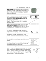
7 Mountthe flashing in theridge
Multiflexridge flashing
placedonthe pipe
Pushthe top60mm downoverthe
pipe andfastenwithdrilling screw
4,8x19w/washer(H71-002)
Ceiling
Fastenthe flashing
on thepipewith
4 screws 4,8x16
(N136-121)
Pushthe rubberbandoverthe
pipe and flashing. Removethe
white edging,and pressthe
rubberband ontothe pipe
Sealupwithweatherstrip
(birds) and fastenwith
screws(H72-016)
Mounted Inlet
Multiflex Ridgecan be used for slopesof 10°,15° and 20°
The sameprocedure
Important! Fasten therubberbandat6points
bothonthe pipe andthe flashingwith screws,
exceptthe screwsatthe rollingjunctions.
Fastenwith screwsclose to theedgeofthe
rollingjunctions
MultiflexRidge canbe used for slopesof 10°,15° and 20°

12
© Munters AB, 2008
© Munters AB, 2008
8 Mount the flashingonone sideof the roof
Pushthe top60mm down over the
pipeand fasten with drilling screw
w/washer 4,8x19 (H71-002)
Multiflexcan be used for slopesof 10°,15° and 20°
4. Cut a slitinthe roof50mm wide and
100mm fromthe multiflex upper edge
on the first topby the
multiflex edge.
Important: Endthe slit in the steel plate
in both sides
5. Mountt
intothe slit witha
he intermediate plate
weatherstrip
underthe steel plate,and fasten
with screws through every top.
7. Placethe plain
sideonthe Multiflex
flashing.Tighten with
siliconeand fasten with
screws throughthe intermediate
plate,the flashingand the roof.
2. Make tight with
weatherstrip (birds),
and fastenthe flashing with screws all
theway round.
Cut of a roof
with steel plate
NB! If the roofis madeof asbestos cement,
put intermediate plate underthe slit, and
the procedureisthe sameas with steel plates
6. Jointinthe corners
after mounting.
100mm
200 mm
300 mm
700 mm
1. Pushthe flashing downth pipe
8. Fastenthe flashing
alongthe sides with
screws.
Pushthe rubber band over the
pipeand flashing. Remove the
white edging,and press the
rubber band ontothe pipe
Important! Fastenthe rubber bandat6points
bothonthe pipeand the flashing with screws,
exceptthe screwsatthe rolling junctions.
Fasten with screws closetothe edgeof the
rolling junctions
Mounted flashing
1. Pushthe flashing downthe pipe

© Munters AB, 2008
13
© Munters AB, 2008
mc35
65 cm
mc001
200cm
9 Mounting flexible flashing
Cutaholeinthe flashing according
to thesizeinthe drawing.
The holecan be moved.
Join theflashingatthe edge.
Fastenthe flashingwith self-drilling
screws 10x1-6(D25-001)
Thisedgeis pushed underslit
If steelplates,use intermediate plate
(seemountingMultiflex flashing)
Theflashingispressed
down aroundthe Inlet
mc57
80 cm
mc051
200cm
TU 600
TU 800

14
© Munters AB, 2008
© Munters AB, 2008
Mount the flange
on the motor with
4set screw 6x16
Fastenthe fanonthe shaft
9 Assembly instruction-Inlet withfan
2. Mountthe fan
on motor suspensions
which are mounted in
thepipe
Airinlet Ø600
Stainless steel
ring
Support-ringis mounted
together with motor fittings
and45° angle iron
Angle
iron
Motor-
fittings
Support-ring
NB!The fanbladesare placed underthe motor
Mount3-motor fittings
inside thepipeinrough-bored
holes
4pcs.
Motorsuspension
cutofthe pipe
Bolt+
nut
2.Mount the fan
on motor suspensions
which are mounted in
thepipeinrough-bored
holes
Airinlet Ø800
Stainless steel
ring
NB!Noticethatthe fanisintop
at Ø800
10
Mount3-motor fittings
inside thepipeinrough-bored
holes
4pcs.
NB!Noticethatthe fanisintop
at Ø800

© Munters AB, 2008
15
© Munters AB, 2008
11 Assembly instruction-Air inlet from loft
ceiling
Cut hole in the ceiling
forthe diffusor part
Hang up theinlet
in 4wires,sothatthe wires
areplacedas close to the
inletas possible
ceiling
Assemblethe wire
with wire clamp
3mmRF
(01-031)
Angle iron
45°
(900-061)
Stay tightener
6mmRF(01-121)
Assemblethe wire
with wire clamp
3mmRF
(01-031)
Theangleiron
is placedon
theinlet
Wire 3mmRF
(01-002)
Insulation
Coachscrew
8*70(02-312)
Clickthe two rollingjunctionstogether
Cutofthe pipe

16
© Munters AB, 2008
© Munters AB, 2008
1
2 Assembly instruction-Regulator arm
on Star diffusor
1.
2.
3.
5.
4.
6.
7.
Theinlet suspension is placedonlevel with this point
The cross-stiffeningonthe backside of the stardiffusoris
so that a linecan be drawnperpendiculartothe side wall.
fastened onlevel with this point. This point must be placed
The adjustabletightening screw
must point downwards when assembling
thewire pulling system
N.B.!! When the stardiffusoris hungup, theRegulator arm
be placedtothe left side,whenyou are standing faced
to thewire pullingcontrol center. (seepage 12)
must
Place the Regulator arm in parallelwiththe red lineonthe hub
(closed diffusor)
12 Assembly instruction-Regulator arm
on Star diffusor
N.B.!! When the stardiffusoris hungup, theRegulator arm
must be placedtothe left side,whenyou are standing faced
to thewire pullingcontrol center. (seepage 12)

© Munters AB, 2008
17
© Munters AB, 2008
Mountthe pipe
on thediffusor
Ceiling
1. Thepipemustbe
placedinthe fold in the
diffusor,sothatthe pipe is
on levelwiththe insideof
thediffusor
.
2. Screw8pcs. sheetmetal screw4,8x16
(N136-121)intothe pipe anddiffusoronlevel with
theinlet suspension in themittelof the fold on
thediffusorapprox.12cm fromthe edge of thediffusor.
13 Assembly instruction-Inlet fromloft
2. Screw8pcs. sheetmetal screw4,8x16
(N136-121)intothe pipe anddiffusoronlevel with
theinlet suspension in themiddle of thefoldon
thediffusorapprox.12cm fromthe edge of thediffusor.

18
© Munters AB, 2008
© Munters AB, 2008
Mount the flange
on the motor with
4set screw 6x16
Fastenthe fanonthe shaft
14 Assembly instruction-Inlet Jupiter withfan
NB !! Thefan bladesmustbeplaced underthe motor
Ceiling
Mount the fan
into the motor fittings
Ceiling
Mountthe top (incl.net)
with 4pcs.sheet metal
screw 4,8x16
Mount3pcs.motor fittings
inside thepipeinrough-bored
holes
Motorsuspension
cutofthe pipe
Bolt+
nut

© Munters AB, 2008
19
© Munters AB, 2008
15 Mount the air distributor under the inlet
Saturn
Fig. 1
Fig. 1
screwthe
into aØ7mm hole
screw eye

20
© Munters AB, 2008
© Munters AB, 2008
16 Mounting the wire pulling system on
diffusors placedin2rows
See fig.1
or 2
Putthe wire through
a snap hookand fasten
with2clamps.
Hangthe weightin the
snap hook
Wire4mm
(01-003
Piano wire 3mm
(L111-029)
The wireand the Piano wireare assembled with
2 Thimblers,1Stay tightenerand 4 Clamps
Fig. 3
Fig.3
Fig.3
Stay tightener
8mm (01-103)
Clamp3mm
(01-031)
Clamp5mm
(01-023)
The wire mustrun 8cm
fromthe ceiling
Fig.4
Fig.4
Fig.1
Oilhydromat
Fig.2
LinakLA32
NB!
The diffusor mustbe closed when mounting
the wire. The Regulatorarm will thenbein
a positionof approx.15° to the wire.
Fastenthe wire on the Regulator arm
55 cm fromthe centerofthe diffusor.
Thimble 5mm
(01-122)
Thimble 5mm
(01-122)
Stop fittings
(120-081)
Stop fittings
(120-081)
Split-pin 5mm
(N136-108)
Clamp5mm
(01-023)
Bar with holes
(B11-125)
Bar with holes
(B11-125)
Bottom fittings
(120-080)
Bottom fittings
(120-080)
Linak
Fig.5
Fig.5
Pianowire3mm
(L111-029)
Wire 4mm (01-003)
When adjusting,the actuator rod
mustbe down (closed). The strokeof
the Oilhydromat and
Linak LA32are 32 cm.
Wire4mm
(01-003
Piano wire 3mm
(L111-029)
Clamps 3mm
(01-031)
Clamps 5mm
(01-023)
Fig.5
Important!! Whenthe diffuseris suspended,the Regulatorarm must
be on theleft, whenyou facethe damper controller (fig.1or 2)
Important!! When thediffusorissuspended, theRegulatorarm must
be on theleft, when you facethe damper controller (fig. 1or2)
/