Page is loading ...

Manual for use and maintenance
including assembling instructions
+ CE Declaration of conformity
WM54 Fiberglass Wall Mount Fan
with Damper Door
Air extraction fan
Ag/MIT/UmGB-2483-07/17 Rev 1.2
WM54F
Wall Mount Fan
With Damper Door

2 | © Munters AB, 2019
Thank You
Thank you for purchasing a Munters WM54F Fiberglass with Damper! Munters equipment is designed to be the highest
performing, highest quality equipment you can buy. With the proper installation and maintenance it will provide many years
of service.
Please Note
To achieve maximum performance and insure long life from your Munters product it is essential that it be installed and
maintained properly. Please read all instructions carefully before beginning installation.
This manual for use and maintenance is an integral part of the apparatus together with the attached technical
documentation and has been produced with reference to Directive 2006/42/EC, paragraph A, Annex II, and to ErP Directive
2009/125/CE Commission Regulation 327/2011.
This document is destined for the user of the apparatus: it may not be reproduced in whole or in part, committed to computer
memory as a file or delivered to third parties without the prior authorisation of the assembler of the system. Munters Italy
S.p.A. reserves the right to effect modifications to the apparatus in accordance with technical and legal developments and
to make alterations to specifications, quantities, etc.,for production or other reasons, subsequent to publication.
Warranty
For Warranty information please refers to "General terms and condition of sale" available on
https://www.munters.com/globalassets/terms-and-policies/condizioni_generali_vendita.pdf
Conditions and Limitations
• Products and Systems involved in a warranty claim under the "General terms
and condition of sale" shall have been properly installed, maintained and
operated under competent supervision, according to the instructions provided
by Munters;
• Malfunction or failure resulting from misuse, abuse, negligence, alteration,
accident or lack of proper installation or maintenance shall not be considered a
defect under the Warranty.

3 | © Munters AB, 2019
CONTENTS
1. CE DECLARATION ....................................................................................................................................... 4
1.1 Disclaimer ............................................................................................................................. 5
1.2 Introduction............................................................................................................................ 5
1.3 Notes ..................................................................................................................................... 5
1.4 Data for Fan Eco Design Directive ......................................................................................... 5
1.5 Disposal ................................................................................................................................ 5
2. SAFETY ASPECTS ....................................................................................................................................... 6
2.1 Personnel requirements......................................................................................................... 6
2.2 General safety instructions .................................................................................................... 6
2.3 Safety devices ....................................................................................................................... 7
2.4 Residual risks ........................................................................................................................ 8
3. OPERATING CONDITIONS .......................................................................................................................... 9
3.1 Intended conditions of use ..................................................................................................... 9
3.2 Non-permitted conditions of use ............................................................................................ 9
4. UNPACKING THE EQUIPMENT ................................................................................................................ 11
4.1 Personnel Requirements ..................................................................................................... 11
4.2 Part List ............................................................................................................................... 11
4.3 Fan Dimensions .................................................................................................................. 13
4.4 Tools Required For Installation ............................................................................................ 13
5. INSTALLATION INSTRUCTIONS .............................................................................................................. 14
5.1 Install ................................................................................................................................... 14
6. ELECTRICAL WIRING................................................................................................................................ 32
7. OPERATION ............................................................................................................................................... 34
8. MAINTENANCE .......................................................................................................................................... 35
9. TROUBLESHOOTING ................................................................................................................................ 36
10. WINTERIZING ........................................................................................................................................... 37
10.1 Winterizing ......................................................................................................................... 37
10.2 Winter Weather Protection ................................................................................................. 37
11. EXPLODED VIEW ..................................................................................................................................... 38
WARNING
All the components and spare parts MUST be storaged in dry and clean environment.

4 | © Munters AB, 2019
1. CE DECLARATION
CE Declaration of Conformity
(complies with Subparagraph A Annex II Directive 2006/42/EC)
Munters Italy S.p.A.
with registered offices in Strada Piani, 2 – 18027 Chiusavecchia (IM) – Italy
(Company Registration nr. 00081050080)
declares on its own responsibility that the apparatus:
Designation
Fan designed for moving air to control temperature and humidity in
greenhouses or rearing sheds
Model
WM54F
Year of manufacture
2017
conforms with the essential safety requirements stated by Apparatus Directive 2006/42/EC
and performance requirements comply with the ERP Directive 2009/125/CE,
with particular reference to the following provisions:
UNI EN 953:2009, UNI EN ISO 12100:2010, UNI EN ISO 12499:2009,
UNI EN ISO 13857:2008, CEI EN 60204-1:2006 (CEI 44-5),
UNI EN ISO 5801:2009
Chiusavecchia, 19
th
September 2019
Massimo Colombo
Legal Representative

5 | © Munters AB, 2019
1.1 Disclaimer
Munters reserves the right to make alternations to specifications, quantities, dimensions etc. for production or other
reasons, subsequent to publication. The information contained herein has been prepared by qualified experts within
Munters. While we believe the information is accurate and complete, we make no warranty or representation for any
particular purposes. The information is offered in good faith and with the understanding that any use of the units or
accessories in breach of the directions and warnings in this document is at the sole discretion and risk of the user.
1.2 Introduction
In order to realize the full benefit from this product it is important that it is installed, commissioned and operated correctly.
Before installation or using the fan, this manual should be studied carefully. It is also recommended that it is kept safely for
future reference. The manual is intended as a reference for installation, commissioning and day-to-day operation of the
Munters fans.
1.3 Notes
Date of release: 2017.
Munters cannot guarantee to inform users about the changes or to distribute new manuals to them.
All rights reserved. No part of this manual may be reproduced in any manner whatsoever without the expressed written
permission of Munters. The contents of this manual are subject to change without notice.
1.4 Data for Fan Eco Design Directive
Product information requirements →
(according to ANNEX I -3.2 of regulation)
1
2
3
4
optional
5
6a
6b
6c
7
8
Fan description
(*)
Overall efficiency η%
Measurement category
Efficiency category
Efficiency grade
Target efficiency grade 2015
VSD must be installed with the fan
Motor power input at optimum
energy efficiency [W]
Flow rate at optimum energy
efficiency [m
3
/h]
Pressure at optimum energy
efficiency [Pa]
RPM at optimum energy
efficiency
Specific ratio
WM54F 1.5hp 3ph 50Hz OS
39,3
A
static
44,9
40
no
1310
30.562
60
510
1
WM54F 2hp 3ph 50Hz OS
39,8
A
static
44,4
40
no
1852
34.755
76
566
1
* Fans tested are configured according to COMMISSION REGULATION (EU) No 327/2011 of 30th March 2011 - ANNEX II - 1.5. Efficiency values, according
to Commission Regulation (EU) 327/2011, refers to exhaust fans only.
1.5 Disposal
Do not dispose of this product with general household waste. This product must be disposed according to the laws
governing Waste Electrical and Electronic Equipment. If required, contact your local authorities for information regarding
the available disposal facilities.

6 | © Munters AB, 2019
2. SAFETY ASPECTS
WARNING
Failure to respect safety or behavioral rules can produce hazardous situations for users as well as
damage to the machine and the place where it is installed. The fan must only be used if it is in perfect operating
condition, by personnel who are perfectly aware of the safety measures and possible hazards, and in strict
compliance with the instructions given in this manual.
2.1 Personnel requirements
Equipment may only be used by personnel who know and apply the specific requirements given in the user and
maintenance manual and the more general instructions contained in various regulations for accident prevention and
applicable legislation regarding safety in the workplace, as well as other European Community directives incorporated by
the member states into their national legislation.
Knowledge and understanding of the manual and of the attached documents constitute an indispensable tool for reducing
hazards and promoting the safety and health of workers.
Personnel training
All operators engaged in the use of the fan must have received adequate information from the employer relating to:
• risks to health and safety at work connected with the use of the machine;
• first aid procedures, fire precautions and evacuation of workplaces;
• devices provided for the safety of operators, and residual risks generated by the machine.
In particular, the employer has the following duties:
• when assigning tasks to operators, to take into account their capabilities in the interests of safeguarding their
health and safety;
• to provide adequate means of protection;
• to require compliance by individual operators with the company rules and provisions regarding safety and the use
of the collective and individual protective measures at their disposal;
• to ensure that normal and special maintenance operations, or in any event operations necessary for machine
safety, are regularly carried out.
All operators must take care of their own safety and health as well as that of other people in the workplace who may be
affected by their actions or omissions, in accordance with their personal skills, and the instructions and means provided to
them by the employer.
WARNING
Unauthorized tampering/replacement of one or more parts of the machine, or the use of accessories,
tools or materials other than those recommended by the manufacturer, are prohibited and release the
manufacturer from all liability.
WARNING
Operators must be trained to deal with the occurrence of possible faults, malfunctions or dangerous
conditions to themselves or others, and in such an event must:
• stop the fan immediately by operating the emergency stop device (mushroom-shaped pushbutton/main
switch mounted on the electrical panel);
• not carry out operations which are beyond their duties and/or technical knowledge.
2.2 General safety instructions
WARNING
• Safety devices must not be removed or rendered ineffective;
• the fan must not be started with guards removed;
• any adjustment or maintenance operation must be performed with the electrical isolating device activated and
locked in position with a padlock;
• any operation is prohibited which may cause arcing or sparks or other situations which could start a fire;
• in the event of alarm signals resulting in the intervention of safety devices, the operator must ask for immediate
action by qualified technicians responsible for maintenance;
• user must ensure that the environmental and electricity supply conditions in which the fan operates are always
within the limits specified in this user manual;
• do not for any reason modify parts of the fan in order to fit additional devices.

7 | © Munters AB, 2019
2.3 Safety devices
In the process of designing and building the fan, the manufacturer adopted the necessary technical solutions to ensure
compliance with fundamental safety requirements: the object of the risk reduction process was to ensure that the operator
can use the fan in safety. The machine is provided with protection devices of fixed type and is fitted with an actuator for
the emergency stop function.
Fixed guards
The fixed guards are solidly fixed to the structure of the machine and cannot easily be eluded: the guards are fixed with
systems which require the use of tools for dismantling.
WARNING
Do not start the fan with fixed guards removed: the guards can only be removed with special tools,
by specialized and trained personnel and with the system stationary (emergency system activated and electricity
and hydraulic fluid isolated). At the end of maintenance operations, the guards which were removed must be
replaced correctly.
Position of guard
Type of guard
Notes
Intake side of fan
Guard of fixed type
made of metal mesh.
Dimensions and positioning in accordance with the instructions in the
standard UNI EN 13857. Removable only by means of special tool.
Outlet side of fan
Guard of fixed type
made of metal mesh.
Dimensions and positioning in accordance with the instructions in the
standard UNI EN 13857. Removable only by means of special tool.
Emergency stop function
The machine must be equipped at the installation stage with an electrical panel, on
which must be installed an actuator for the emergency stop function, which when
operated brings dangerous movements to a halt by isolation of the power supply: the
button must be mushroom-shaped and coloured red, provided with mechanical
restraint and released by turning.

8 | © Munters AB, 2019
2.4 Residual risks
Mechanical hazards
Part of machine/stage of use
Description
Plates/provisions/PPE
Installation of machine
Hazard arising from failure to observe
ergonomic principles, caused by
excessive strain, i.e. generic
mechanical hazard during the moving
and installing stages of the machine.
Electrical hazards
System area
Description
Plates/provisions/PPE
Panels, covers and electrical
apparatus.
The safety signs must be fixed in an
extremely visible position on the door of
the electrical panel and on covers
containing electrical apparatus, to
highlight the risks to which an operator
could be exposed in the event of
opening the electrical panel (danger
resulting from the presence of live
parts), the level of voltage present, the
prohibition of tampering by
unauthorized personnel and the
prohibition on the use of liquids on
electrical apparatus in the event of fire.
Hazards generated by noise
(measured at 2m distance)
Fan model
Sound pressure level Lp [dB(A)]
WM54HF – 1.5 hp
77.2
WM54HF – 2.0 hp
77.6
WARNING
The user and the employer must comply with current national law in terms of protection against
daily personal exposure of operators to noise, by providing the use of personal protective equipment (earmuffs,
earplugs, etc.) if necessary, depending on the overall level of sound pressure in the installation area, and the daily
personal exposure of the employees. In areas where the overall sound level reaches excessive values, personal protective
equipment must be used.
WARNING
The fan must only be used if it is in perfect operating condition, by personnel, aged more than 14
years who are perfectly aware of the safety measures and possible hazards, and in strict compliance with the
instructions given in this manual.

9 | © Munters AB, 2019
3. OPERATING CONDITIONS
3.1 Intended conditions of use
Fans are machines designed for moving air to control temperature and humidity in greenhouses or rearing sheds by
extraction, not under pressure. They can even be installed horizontally, without altering or modifying their characteristics.
Normal ambient temperature limits are -15°C to +40°C. Maximum altitude is 1000m above sea level. Should a fan be
required to operate at a higher altitude, the loss in mass flow (heat removing capacity) due to lower air density should be
taken into consideration.
The fan has been designed and built to operate in safety for the user, if used according to the conditions intended by the
manufacturer and stated in this user and maintenance manual.
NOTE
For further information, please refer to the technical documentation attached to this manual.
3.2 Non-permitted conditions of use
Total or partial failure to observe the instructions given in this manual could cause damage to the fan and/or people.
The following uses are to be considered not permitted and improper:
• use in the event of faults and/or tampering with the installed safety devices;
• use by personnel not specifically trained;
• installation of the fan for extraction or circulation under pressure;
• use contrary to existing regulations;
• incorrect installation differing from instructions given in this manual;
• supply from an electrical network with characteristics different from that specified in the wiring diagram;
• total or partial failure to observe instructions;
• insufficient maintenance;
• use of non-original spare parts;
• use of lubricants with characteristics different from those specified in the technical documentation attached to the
manual;
• use by minors;
• use under the influence of drugs, alcohol, etc.
WARNING Use of the fan other than as described in the user manual or outside the operational limits laid down
by the manufacturer is considered IMPROPER USE. In the event of IMPROPER USE the manufacturer declines
all liability in relation to any damage that may be caused to persons or property, and any kind of warranty will be
considered invalidated.

10 | © Munters AB, 2019
Use of non-original spare parts
Original spare parts ensure the reliability and safety of the operation of the fan: in the event of maintenance/replacement,
consult the spare parts list, the list of parts and components used and the relevant technical documentation attached to
this manual.
WARNING In the event of replacement of safety devices, it is essential to maintain the safety and operational
characteristics of the original device, preferring replacement with an identical component.
Insufficient maintenance
A correct normal maintenance is one that maintains the original integrity or restores the fan’s efficiency, while at the same
time limiting normal deterioration resulting from use.
Special maintenance work can also prolong the usable life of the machine and/or, secondarily, can improve its efficiency,
reliability, productivity and ease of maintenance and inspection.
Unauthorized modifications or tampering
No operation is permitted which is aimed at making modifications to the fan and the safety devices fitted to it; similarly, it
is not possible to alter its operational and performance characteristics.
WARNING Interference with the command and control circuits is prohibited: such operations could cause damage
to the equipment and serious danger to the operator.
NOTE Modifications made to the fan which do not come into the categories of normal and special maintenance,
or which alter its operational and performance characteristics, invalidate the machine’s compliance with the
requirements of the applicable directives, as attested by the manufacturer with the EC declaration of conformity:
it is up to the person responsible for the modification to resubmit the machine to the assessment conformity procedures
specified in the applicable directives.
Use in a potentially explosive atmosphere
The fan has been designed and built to operate in environments where the presence of a potentially explosive atmosphere
is not expected, in other words it is not intended to handle materials which release explosive dust. Emission into the
atmosphere of harmful particles or gases must be contained within the limits established by current regulations.
WARNING The fan has been designed and built in such a way that it CANNOT operate in a classified area,
according to directive 1999/92/EC.
WARNING The metal sheets used for constructing the metal parts of the have a surface coating made of an alloy
of Zinc, Aluminum and Magnesium, classified as Zm120 (equivalent to 9 μm of coating thickness on each side of
the panels) which corresponds to a corrosion resistance in salty mist of 1800 hours.
Whenever it is intended to use the fans in ambients characterized by the presence of particularly aggressive agents
(ammonia, clavulanic acid, etc.) the user, before installing the fan at the installation site must verify that the environmental
conditions are compatible with the intended use of the materials that compose the fan.

11 | © Munters AB, 2019
4. UNPACKING THE EQUIPMENT
WARNING
Failure to respect safety or behavioral rules can produce hazardous situations for users as well as
damage to the machine and the place where it is installed. The fan must only be used if it is in perfect operating
condition, by personnel who are perfectly aware of the safety measures and possible hazards, and in strict
compliance with the instructions given in this manual.
4.1 Personnel Requirements
Equipment may only be used by personnel who know and apply the specific requirements given in the user and
maintenance manual and the more general instructions contained in various regulations for accident prevention and
applicable legislation regarding safety in the workplace, as well as other European Community directives incorporated by
the member states into their national legislation.
Knowledge and understanding of the manual and of the attached documents constitute an indispensable tool for reducing
hazards and promoting the safety and health of workers.
WARNING
Operators must be trained to deal with the occurrence of possible faults, malfunctions or dangerous
conditions to themselves or others, and in such an event must:
• stop the fan immediately by operating the emergency stop device (mushroom-shaped pushbutton/main
switch mounted on the electrical panel);
• not carry out operations which are beyond their duties and/or technical knowledge.
4.2 Part List
Each WM54F requires:
1 – 54” Fiberglass Orifice
1 – 54” Propeller
1 – Central Support
1 – Motor
1 – Motor pulley
1 – Drip Shield
1 – Main Frame Assembly
1 – Plastic Door Assembly
4 – Plastic Cone Sections
1 – Round Safety Mesh
1 – Flat Safety Mesh
1 – Motor slide
1 – Tensioner bracket
4 – Cone Support Brackets
4 – Cone/Strut Mounting Bracket
1 – V-belt
1 – Hub with Bearings & Shaft
1 – Central Pulley
1 – Belt tensioner
1 – Motor stiffener bracket
2 – Tension Spring
1 – Cable
Bolts and Nuts

12 | © Munters AB, 2019
Bolts and nuts for 1 – WM54F Fan Installation
[A]…. 28 – Ø8x32 Washer
[B]…. 2 – Ø6.3x19 Self-tapping Screw
[C]…. 4 – M8x25 Hex Screw
[D]…. 4 – Ø8 Ext Toothed Washer
[E]…. 4 – M8 Hex Nut
[F]…. 4 – M6x30 Hex Screw
[G]…. 4 – M6 Hex Nut with Flange
[H].... 4 – Ø8x24 Washer
[I]…. 1 – M10x25 Hex Screw
[J].... 1 – D10 Spring Washer
[K]…. 1 – M25 Hex Nut
[L]…. 1 – Waterproof distence piece
[M]…. 1 – Cup Cover Nut
[P]…. 12 – Plastic Clip
[Q]…. 1 – Cable
[R]…. 4 – Cable Clamp
[S]…. 1 – M10x50 Hex Screw
[AA]…. 18 – M8x30 Hex Screw
[BB]…. 4 – M8x45 Hex Screw
[CC]…. 7 – M8x65 Hex Screw
[DD]…. 33 – M8 Hex Nut with Flange
[EE]….. 8 – Ø4.8x13 Self-tapping Screw
WARNING
Unauthorized tampering/replacement of one or more parts of the machine, or the use of accessories,
tools or materials other than those recommended by the manufacturer, are prohibited and release the
manufacturer from all liability.

13 | © Munters AB, 2019
4.3 Fan Dimensions
Fan Specifications: 50Hz shown
Voltage: 230/400 VAC
Phase: 3
DIMENSIONS
Size
A
B
C
D - Dia
E
F
Wall Opening
54”
1524 x 1524
1245
185 max
1684
81
121
1435 x 1435
4.4 Tools Required For Installation
Pneumatic screwdriver
8mm Spanner
17mm Spanner
10mm Long Spanner
13mm Long Spanner
36mm Spanner
Screw Head Adaptor
Small Hammer
10mm Combination Spanner
Screwdriver
17mm Combination Spanner
WARNING
The user and the employer must comply with current national law in terms of protection against daily
personal exposure of operators to noise, by providing the use of personal protective equipment
(earmuffs,earplugs, etc.) if necessary, depending on the overall level of sound pressure in the installation area,
and the daily personal exposure of the employees. In areas where the overall sound level reaches excessive values,
personal protective equipment must be used.

14 | © Munters AB, 2019
5. INSTALLATION INSTRUCTIONS
5.1 Install
Step 1
Construct framed opening to correct size according to the Wall Opening listed in chart A below. See Figure 1. When
installing exterior sheet metal before fan, leave 50mm of the framing exposed on all sides so the orifice can mount flush to
the frame.
Wall Opening
Minimum Spacing
Center To Center
Fan Diameter
(W. x H.)
“Z”
Dimension
54”
1435 x 1435
305 recommended; 90 minimum
1524 Minimum
NOTE
Damper doors should be carefully set aside out of direct sunlight until needed.
Figure 1
Frame Construction
WARNING
In case of a sandwich panel installation, the fans cannot be fixed directly on the "foam" sidewall, but
a proper metal supporting structure shall be used for steadily holding the fans in place as shown in Figure 1.
WARNING
There must be no obstacle neither in front or behind the fans. The outgoing airflow must be kept
free at least of a length of 3-times fan diameter and the ingoing airflow must be kept free at least in a radius of
1.5 m distance in front of the fan.

15 | © Munters AB, 2019
Step 2
Place the Central Support on saw horses or a flat work surface. The large center hole should be pointing horizontally.
Attach the Motor Slide and the Tensioner Bracket to the Central Support using (3) Long Bolts [CC], (4) Washers [A] and
(3) Nuts [DD]. The Motor Slide and the Tensioner Bracket share the middle hole. See Figure 2.
Figure 2
Step 2B
Attach the 3” Tensioner Pulley to the Belt Tensioner using Bolt [S]. Then attach the Belt Tensioner assembly to the
Tensioner Bracket using Bolt [I] and Washer [J]. The Belt Tensioner has to be perpendicular to the Central Support. Hold
tensioner at this setting and tighten the 10mm bolt to 50 Nm. See Figure 2B.
Figure 2B

16 | © Munters AB, 2019
Step 3
Attach Central Pulley to Hub using (4) Bolts [F] and Nuts [G] and tighten to 14 Nm. See Figure 3.
Figure 3
Step 4
Rotate the Central Support on the saw horses so the Motor Slide is pointing up. Then slide the Waterproof Distance Piece
[L] over the hub shaft as shown in Figure 4. Attached the Pulley/Hub Assembly to the Central Support using (1) Hex Nut
[K] and tighten to 60 Nm. See Figure 4. Then place the Cup Cover Nut [M] over the Hex Nut and fasten in place with (1)
Tapping Screw [B]. See Figure 4. Set aside the Support Assembly for use in a later step.
Figure 4

17 | © Munters AB, 2019
Step 5
Place Fiberglass Orifice on saw horses with the round orifice pointing up and place (1) Cone/Strut Mounting Bracket in
each corner of the Fiberglass Orifice. See Figure 5.
Figure 5
Step 6
The corners of the Fiberglass Orifice with 2 holes on the diagonal are the corners where the Support Assembly attaches.
Attach the Support Assembly using (4) Long Bolts [CC], (4) Washers [A] and (4) Nuts [DD] and in the opposite corners
attach the Cone/Strut Mounting Bracket to the orifice using (1) Short Bolt [AA], Washer [A] and Nut [DD]. See Figure 5.
Figure 6

18 | © Munters AB, 2019
Step 7
Insert the V-belt over the Central Pulley.
Attach Propeller to Hub Assembly using (4) Bolts [C], Washers [D] and Nuts [E] and tighten to 22 Nm. See Figure 7.
Figure 7
Step 8
Slide the Main Frame Assembly onto the Fiberglass Orifice with the pin on the Main Frame opposite the drain hole. See
Figure 8A.
Line up the 4 holes in the Main Frame with the holes in the orifice and fasten using (8) Self-tapping Screws [EE] paying
attention to stay at least 15 mm from the Orifice edge to avoid damaging it. See Figure 8B.
Figure 8A Figure 8B

19 | © Munters AB, 2019
Step 9
Attach Drip Shield to bottom of framed opening using (3) proper Screws (Not Provided). See Figure 9A and 9B. If a
100mm wall is used a support board must be installed as shown in Figure 9B. Be sure not to deform Drip Shield when
installing screws.
Figure 9A Figure 9B
Step 10
Locate the Drain hole in the Fiberglass Orifice. This is the bottom of the Orifice. Set the bottom edge of the panel on the
Drip Shield ledge and center the panel on the opening. Then secure the Orifice to the wall using (16) proper screws (Not
Provided). See Figure 10A and 10B.
NOTE
The proper type of fixing screw has to be selected depending on the material of the wall of the installation.
Figure 10A Figure 10B

20 | © Munters AB, 2019
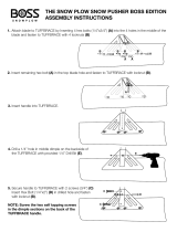
Step 11
Carefully remove folded Butterfly assembly from box. Open doors and lay them flat on solid surface with the Munters Logo
down. The Bottom of the doors has the Hinge Pin with the Nylon Washers. The Wing sits down in the Groove of the upper
right and lower left doors. The Wing will start just after the last spring mounting dimple and follow the Groove. Make sure
Wing is seated in bottom of Groove and fasten in place using (3) Seal-Washer Screws per wing present in the butterfly
package. Make sure Hinge Pins do not fall out. See Figure 11.
Figure 11
/