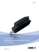
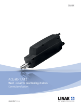
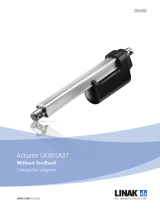
Linak MEDLINE LA32 User manual

Type
User manual

This manual is also suitable for

PRODUCT DATA SHEET
ACTUATOR
LA32
Features:
24 V DC permanent magnet motor
Thrust up to 6000 N (with ball screw)
Stainless steel piston rod
High-strength plastic housing protects motor
and gears
Elegant and compact design with small
installation dimensions
Protection class: IPX1
• Colour: black
2250 mm straight cable with 6.3 mm jack plug
Low noise level: 46 dB (A); measuring method
DS/EN ISO 3746, actuator not loaded
LA32K with ball screw and double-acting brake
(i.e. push and pull / both directions)
Options:
Protection class: IPX5 or IPX6
Reed-switch for exact positioning (8 pulses per
spindle revolution)
LA32 with 5 mm pitch F: Manual quick release
LA32 with 5 mm pitch FH: Manual quick release
with dampened movement
Mechanical splines function (push only)
Electrical splines function, built-in micro-switch in
back fixture, the actuator can therefore only be
used for push. (Only with 01 and 02 back fixture)
LA32K with ball screw and double-acting brake
(i.e. push and pull/both directions)
LA32KAS with ball screw and safety nut
LA32KSM with ball screw, safety nut and
mechanical splines
Available with 0.2 m or 0.4 m coiled cable
LA32JKSM available with 2-speed facility for the
LINAK JUMBO SYSTEM
CS32; electronic limit switch (built-in)
Usage:
Duty cycle: Max. 10% or 2 minutes continuous use
followed by 18 min. not in use
Ambient temperature +5° to +40° C
For use with LINAK control boxes CB8, CB12, CB14
and CS16 PCB or internal CS32 PCB
Should LA32 be used with a non LINAK control
unit, please ask the nearest LINAK representative
for further details
Accessories::
CS16; electronic limit switch
• Optical encoder
SLS: safety limit switch
The LA32 is a powerful actuator that can be supplied
with a ball screw spindle to give outstanding perfor-
mance. The ideal choice for a wide range of applica-
tions including adjustment of hospital beds.
The LA32 has many special options including a safety
nut, splines, quick release (F) and an optional protec-
tion class up to IPX6 standard.
32 1 1 0 0 +
0
0400
250
Cables: Jack cable (General tolerance +/- 0.07m)
0 = *Straight 2.3 m 5 = Straight without plug 1 m (CS) always black
1 = *Straight 1.05 m X = *Other cablel/ length
2 = *Coiled 0.4 m * always the same colour as the actuator
3 = *Coiled 0,2 m
4 = Straight without plug 0,5 m (Potentiometer) always black
Protection Class: 0 = IPX1
1 = IPX5
2 = IPX6 Washable
Motor type: 0 = 24V 4 = 24V L-motor standard motor, will always have to
1 = 24V S-motor be chosen for use with a LINAK control box.
2 = 12V S-motor 5 = 12V motor
3 = 24V Jumbo motor
Stroke length: XXX = mm Max. 400 mm for 3-6 mm pitch (up to 600 mm with special (20%) items
Max. 500 mm for 9-12 mm pitch (up to 600 mm with special (20%) items
Min. 100 mm
Install. dim. 0 = Standard
X = Other install. dim.
Option: 0 = None 4 = Brake
1 = Safety nut 5 = Brake with safety nut.
2 = Steel splines
3 = Steel splines with safety nut.
Colour: + = Grey
- = Black
Option: 0 = None
F = Quick release (F) H = Quick release, dampened movement(FH)
Positioning C/S 0 = None
Optical encoder: P = Potentiometer 1 kohm R = Reed switch
L = Potentiometer 5 Kohm D = Optical encoder
T = Potentiometer 10 Kohm
Y = CS 32A mount. (Not IP65 / 66)
Z = CS 32B mount.
C = CS 32C mount.
Back Fixture: 1 = Standard 5 = Large standard
2 = Turned 90 degrees 6 = Large turned 90 degrees
A = Standard with El-splines
B = Turned 90 degrees with El-splines
Spindle type: 1 = 3 mm (1 threaded) 7 = 12 mm (4-threaded)
2 = 6 mm (2 threaded) 8 = 5 mm (2-threaded)
3 = 9 mm (3 threaded) K = Ball spindle
4 = 4 mm (2 threaded)
5 = 2,5 mm (1 threaded)
Actuator type: 32 = LA32
Precautions:
As there is friction in the spindle/gear system, a load of 800 N is necessary to start the lowering function
with LA32F. The actuator will use up to 3.5 Amp. in inward direction unloaded due to a brake system
that is fitted as standard on all types of LA32F.
Release of the QR is only possible with a Bowden cable release force 25-60 N.
The piston rod eyes are “crimped” in place and cannot be screwed loose
Protective cap
“Crimped” piston rod eye Piston rod without eye
Piston rods without eyes are not tested
LA32 with quick release and free wheeling function must not be sold to new products
Maximum load in pull = 2000N
LA32
Ordering example:
Dimension
Installation dimensions: S + 173: (with/without safety nut)
(Min. install dim. 273 mm) S + 181: (LA323. with/without safety nut)
S + 184: with splines
S + 198: with splines and safety nut
S + 210: LA32K, LA32KAS, LA32 with safety nut
S + 215: with brake
S + 267: LA32KSM
Install. dimensions: S + 173: LA32.F
S + 196: LA32FH
LA32 with quick release:
3D view of the back fi xture.
(here type “01” is shown.
Drawing no.: 0321200
112
23
0
+0.2
6.1
Length
28
-0.2
0
25.9
0
+0.2
6.1
Ø21.9
20
Ø
-0.2
0
25.9
Ø30
Ø
0
+0.1
10.1
Ø
0
+0.2
10.1
30
51
24.5
1311
30
204
S S + 173
Ø36
0
+0.2
16
36
18
Ø
0
+0.2
12.1
99
LA32001B
LINAK A/S
Drawing no.: LA32F001C
02
05
06
01
01 02 05 06
Technical specifications:
Type
321xxx+00xxx4xx
322xxx+00xxx4xx
322xxx+40xxx4xx
32Kxxx+x0xxx4xx
32Kxxx+10xxx4xx
32Kxxx+30xxx4xx
328xxF+x0xxx4xx
32Kxxx+30xxx3xx
(2000N)
4.5
9.5
(7500N)
#
#
(2000N)
13.6/8.5
15/6.5
(7500N)
3000
3000
3000
Push
7500
P
= Stroke lengths where potentiometer is possible as standard
* LINAK control boxes are designed so that they will short-circuit the motor terminals (poles) of the actuator(s) when the actuator(s) are not
running. This solution gives the actuator(s) a higher self-locking ability. If the actuator(s) are not connected to a LINAK control box the termi-
nals of the motor must be short-circuited to achieve the above mentioned self-locking ability.
# = Not with spindle potentiometer (stroke length max. 220 mm)
K = Ball screw
KAS = Ball screw with safety nut
KSM = Ball screw with splines and safety nut
R = Reed-switch
F = Manual quick release
FH = Manual quick release with dampened movement
KAS and KSM are only available on LA32K (with ball screw)
The above measurements are made in connection with a CB12, the LA32JKSM with a CBJ1 high speed.
Graphs:
LA32 current v´s load
0
0,5
1
1,5
2
2,5
3
3,5
4
4,5
5
0 1000 2000 3000 4000 5000 6000
Thrust (Nm)
Amp.
6mm pitch
5mm pitch
3mm pitch
Ball screw
Thrust (N)
LA32 speed v´s load
0
2
4
6
8
10
12
14
16
0123456
Thrust KN
Speed (mm/s)
3mm pitch
Ball screw
6mm pitch
5mm pitch
Thrust (N)
1000 2000 3000 4000 5000 6000
Measurements are made in connection with a CB12
Terms of use
The user is responsible for determining the suitability of LINAK products for specifi c application.
LINAK takes great care in providing accurate and up-to-date information on its products.
However, due to continuous development in order to improve its products, LINAK products are
subject to frequent modifi cations and changes without prior notice. Therefore, LINAK cannot
guarantee the correct and actual status of said information on its products.
While LINAK uses its best efforts to fulfi l orders, LINAK cannot, for the same reasons as
mentioned above, guarantee the availability of any particular product. Therefore, LINAK reserves
the right to discontinue the sale of any product displayed on its website or listed in its catalogues
or other written material drawn up by LINAK.
All sales are subject to the Standard Terms of Sale and Delivery for LINAK. For a copy hereof,
please contact LINAK.
Copyright ® LINAK 2010.03 . MA M9-02-060-N . Chapter 5.9
  • Page 1 1
  • Page 2 2
  • Page 3 3
  • Page 4 4

Linak MEDLINE LA32 User manual

Type
User manual
This manual is also suitable for

Ask a question and I''ll find the answer in the document

Finding information in a document is now easier with AI