Page is loading ...


2 CY4672 Reference Design Guide, Document # 001-16968 Revision **
Copyrights
Copyrights
© Cypress Semiconductor Corporation, 2007. The information contained herein is subject to change without notice. Cypress
Semiconductor Corporation assumes no responsibility for the use of any circuitry other than circuitry embodied in a Cypress
product. Nor does it convey or imply any license under patent or other rights. Cypress products are not warranted nor
intended to be used for medical, life support, life saving, critical control or safety applications, unless pursuant to an express
written agreement with Cypress. Furthermore, Cypress does not authorize its products for use as critical components in life-
support systems where a malfunction or failure may reasonably be expected to result in significant injury to the user. The
inclusion of Cypress products in life-support systems application implies that the manufacturer assumes all risk of such use
and in doing so indemnifies Cypress against all charges.
Cypress, the Cypress Logo, PRoC, and WirelessUSB are trademarks or registered trademarks of Cypress Semiconductor
Corporation. Windows is a registered trademark of Microsoft Corporation. All other product or company names used in this
manual may be trademarks, registered trademarks, or servicemarks of their respective owners.
Any Source Code (software and/or firmware) is owned by Cypress Semiconductor Corporation (Cypress) and is protected by
and subject to worldwide patent protection (United States and foreign), United States copyright laws and international treaty
provisions. Cypress hereby grants to licensee a personal, non-exclusive, non-transferable license to copy, use, modify, create
derivative works of, and compile the Cypress Source Code and derivative works for the sole purpose of creating custom soft-
ware and or firmware in support of licensee product to be used only in conjunction with a Cypress integrated circuit as speci-
fied in the applicable agreement. Any reproduction, modification, translation, compilation, or representation of this Source
Code except as specified above is prohibited without the express written permission of Cypress.
Disclaimer
CYPRESS MAKES NO WARRANTY OF ANY KIND, EXPRESS OR IMPLIED, WITH REGARD TO THIS MATERIAL,
INCLUDING, BUT NOT LIMITED TO, THE IMPLIED WARRANTIES OF MERCHANTABILITY AND FITNESS FOR A PAR-
TICULAR PURPOSE. Cypress reserves the right to make changes without further notice to the materials described herein.
Cypress does not assume any liability arising out of the application or use of any product or circuit described herein. Cypress
does not authorize its products for use as critical components in life-support systems where a malfunction or failure may rea-
sonably be expected to result in significant injury to the user. The inclusion of Cypress' product in a life-support systems appli-
cation implies that the manufacturer assumes all risk of such use and in doing so indemnifies Cypress against all charges.
Use may be limited by and subject to the applicable Cypress software license agreement.
[+] Feedback

CY4672 Reference Design Guide, Document # 001-16968 Revision ** 3
Contents
1. Introduction 9
1.1 Scope...........................................................................................................................9
1.2 Chapter Overviews .....................................................................................................9
1.3 Support........................................................................................................................9
1.4 Conventions...............................................................................................................10
1.4.1 Definitions ......................................................................................................10
1.4.2 Acronyms.......................................................................................................10
2. WirelessUSB™ Protocol 2.2 13
2.1 General Overview......................................................................................................13
2.1.1 Radio Channel Management .........................................................................13
2.1.2 Pseudo Noise Codes .....................................................................................13
2.1.3 Chip Error Correction.....................................................................................14
2.1.4 Automatic Acknowledgment (AutoACK).........................................................14
2.1.5 Network ID .....................................................................................................14
2.1.6 Manufacturing ID............................................................................................14
2.1.7 Channel Selection Algorithm..........................................................................15
2.2 Protocol Modes..........................................................................................................15
2.2.1 Ping Mode (Bridge Only)................................................................................16
2.2.2 Idle Mode (HID only)......................................................................................17
2.2.3 Reconnect Mode (HID only)...........................................................................17
2.2.4 Button Bind Mode...........................................................................................17
2.2.5 Enhanced KISSBind™...................................................................................18
2.2.6 Unbind............................................................................................................20
2.2.7 Data Mode......................................................................................................20
2.2.8 Back Channel Data Support...........................................................................20
2.2.9 Dynamic Data Rate and Dynamic PA.............................................................22
2.3 Packet Structures ......................................................................................................23
2.3.1 Bind/KISSBind Request Packet (HID) ...........................................................23
2.3.2 Bind Response Packet (Bridge) ....................................................................24
2.3.3 Connect Request (HID)..................................................................................24
2.3.4 Connect Response Packet (Bridge)...............................................................24
2.3.5 Ping Packet (Bridge) .....................................................................................25
2.3.6 Data Packet/Back Channel Data Packet (Bridge and HID)............................25
2.4 Bind and Reconnect Timing.......................................................................................26
2.5 Signature Byte ...........................................................................................................28
2.6 Encryption .................................................................................................................29
2.6.1 TEA Encryption..............................................................................................29
2.6.1.1 TEA Key Management over WirelessUSB.......................................29
2.6.2 AES Encryption..............................................................................................30
2.6.2.1 AES Key Management.....................................................................31
2.6.3 Encryption and Power Consumption Trade Off..............................................31
[+] Feedback

4 CY4672 Reference Design Guide, Document # 001-16968 Revision **
Contents
3. Mouse 33
3.1 Introduction................................................................................................................33
3.1.1 Design Features ............................................................................................33
3.2 Hardware Overview...................................................................................................33
3.2.1 RDK Mouse Assembly...................................................................................33
3.2.2 Hardware Block Diagram...............................................................................35
3.2.3 Schematics ...................................................................................................35
3.2.4 Hardware Considerations .............................................................................36
3.3 Firmware Architecture ...............................................................................................36
3.3.1 ROM/RAM Usage..........................................................................................36
3.3.2 PRoC LP Device Configuration......................................................................36
3.3.2.1 Global Configuration........................................................................38
3.3.2.2 SPI Master User Module .................................................................38
3.3.2.3 Programmable Interval Timer User Module.....................................39
3.3.2.4 Flash Security..................................................................................39
3.3.3 Model.............................................................................................................39
3.3.4 Common Code...............................................................................................40
3.3.4.1 Generated Library Code..................................................................40
3.3.4.2 Debounce Module ...........................................................................40
3.3.4.3 SPI Module......................................................................................40
3.3.4.4 Radio Driver.....................................................................................41
3.3.4.5 Protocol Module...............................................................................41
3.3.4.6 Flash Module...................................................................................41
3.3.4.7 Port Module .....................................................................................41
3.3.4.8 Poll Module......................................................................................41
3.3.4.9 Timer Module...................................................................................41
3.3.4.10 ISR Module......................................................................................42
3.3.5 Application Code............................................................................................42
3.3.5.1 Mouse Module.................................................................................42
3.3.5.2 Optical Module.................................................................................43
3.3.5.3 Testmode Module............................................................................43
3.3.5.4 Buttons Module................................................................................44
3.3.5.5 Mfgtest Module................................................................................44
3.3.5.6 Wheel Module..................................................................................44
3.3.5.7 Battery Module ................................................................................45
3.3.6 Configuration Options....................................................................................45
3.3.6.1 MOUSE_REPORT_IN_MS .............................................................45
3.3.6.2 MOUSE_ACTIVE_MS.....................................................................45
3.3.6.3 MOUSE_DISCONNECTED_POLL_MS..........................................45
3.3.6.4 MOUSE_TX_TIMEOUT_MS ...........................................................45
3.3.6.5 MOUSE_CONNECT_ATTEMPT_TIMES........................................46
3.3.6.6 PLATFORM_H ................................................................................46
3.3.6.7 MOUSE_800_NOT_400_CPI..........................................................46
3.3.6.8 MOUSE_BATTERY_STATUS.........................................................46
3.3.6.9 MOUSE_TEST_MODE ...................................................................46
3.3.6.10 MFG_TEST_CODE.........................................................................46
3.3.6.11 MFG_TX_MODES...........................................................................46
3.3.6.12 MASTER_PROTOCOL ...................................................................46
3.3.6.13 PAYLOAD_LENGTH.......................................................................46
3.3.6.14 KISS_BIND......................................................................................47
3.3.6.15 RSSI_QUALIFY...............................................................................47
3.3.6.16 AUTO_CONNECT...........................................................................47
3.3.7 Platform and Architecture Portability..............................................................47
[+] Feedback

CY4672 Reference Design Guide, Document # 001-16968 Revision ** 5
Contents
3.3.8 Initialization ....................................................................................................47
3.3.9 Wireless Protocol Data Payload.....................................................................47
3.3.9.1 Packet Format 1...............................................................................48
3.3.9.2 Packet Format 2...............................................................................48
3.3.9.3 Packet Format 3...............................................................................48
3.3.10 Interrupt usage and timing .............................................................................48
3.3.11 Code Performance Analysis...........................................................................49
3.4 Development Environment ........................................................................................49
3.4.1 Tools...............................................................................................................49
3.4.2 Tips and Tricks...............................................................................................50
3.4.2.1 M8C Sleep.......................................................................................50
3.4.2.2 Watchdog Timer...............................................................................50
3.4.3 Critical Test Points..........................................................................................50
4. Keyboard 51
4.1 Introduction................................................................................................................51
4.1.1 Design Features.............................................................................................51
4.2 Hardware Overview ...................................................................................................51
4.2.1 RDK Keyboard Assembly...............................................................................52
4.2.2 Schematic ......................................................................................................54
4.2.3 Keyboard Matrix.............................................................................................55
4.2.4 Hardware Considerations...............................................................................55
4.3 Firmware Architecture................................................................................................56
4.3.1 ROM/RAM usage...........................................................................................56
4.3.2 enCoRe II Device Configuration.....................................................................56
4.3.2.1 Global Configuration........................................................................58
4.3.2.2 SPI Master User Module..................................................................59
4.3.2.3 Programmable Interval Timer User Module.....................................59
4.3.2.4 Flash Security..................................................................................59
4.3.3 Model .............................................................................................................60
4.3.4 Common Code...............................................................................................60
4.3.4.1 Generated Library Code ..................................................................60
4.3.4.2 Radio Driver.....................................................................................60
4.3.4.3 Protocol Module...............................................................................61
4.3.4.4 Flash Module ...................................................................................61
4.3.4.5 ISR Module......................................................................................61
4.3.4.6 Timer Module...................................................................................61
4.3.5 Application Code............................................................................................61
4.3.5.1 Keyboard Module.............................................................................61
4.3.5.2 Mfgtest Module ................................................................................62
4.3.5.3 Battery Module.................................................................................62
4.3.5.4 Test Module.....................................................................................62
4.3.5.5 Encrypt Module................................................................................63
4.3.6 Configuration Options ....................................................................................63
4.3.6.1 KEYBOARD_KEEP_ALIVE_TIMEOUT...........................................63
4.3.6.2 KEY_DOWN_DELAY_SAMPLE_PERIOD......................................63
4.3.6.3 KEYBOARD_DEBOUNCE_COUNT................................................63
4.3.6.4 KEYBOARD_MULTIMEDIA_SUPPORT .........................................63
4.3.6.5 KEYBOARD_TEST_MODES...........................................................64
4.3.6.6 KEYBOARD_TEST_MODE_PERIOD.............................................64
4.3.6.7 PANGRAM_TEST_MODE...............................................................64
4.3.6.8 KEYBOARD_BATTERY_VOLTAGE_SUPPORT............................64
4.3.6.9 LP_RDK_KEYBOARD_MATRIX .....................................................64
[+] Feedback

6 CY4672 Reference Design Guide, Document # 001-16968 Revision **
Contents
4.3.6.10 KEYBOARD_TX_TIMEOUT............................................................64
4.3.6.11 TIMER_CAL ....................................................................................64
4.3.6.12 ENCRYPT_TEA ..............................................................................64
4.3.6.13 ENCRYPT_AES ..............................................................................64
4.3.6.14 MFG_TEST_CODE.........................................................................64
4.3.6.15 MFG_ENTER_BY_PIN....................................................................64
4.3.6.16 MFG_TX_MODES...........................................................................65
4.3.6.17 MOUSE_EMULATION_MODE........................................................65
4.3.6.18 BACK_CHANNEL_SUPPORT ........................................................65
4.3.6.19 MASTER_PROTOCOL ...................................................................65
4.3.6.20 PAYLOAD_LENGTH.......................................................................65
4.3.6.21 KISS_BIND......................................................................................65
4.3.6.22 RSSI_QUALIFY...............................................................................65
4.3.6.23 PLATFORM_H ................................................................................65
4.3.7 Platform and Architecture Portability..............................................................65
4.3.8 Initialization....................................................................................................66
4.3.9 Wireless Protocol Data Payload ....................................................................66
4.3.9.1 Keyboard Application Report Formats.............................................66
4.3.10 Ghost Key Detection......................................................................................70
4.3.11 Interrupt Usage / Timing ................................................................................70
4.3.12 Code Performance Analysis ..........................................................................71
4.4 Modifying the Keyboard Matrix or Adding New Keys ................................................72
4.4.1 Modifying the Keyboard Matrix ......................................................................72
4.4.2 Adding New Keys ..........................................................................................72
4.5 Development Environment........................................................................................73
4.5.1 Tools ..............................................................................................................73
4.5.2 Tips and Tricks...............................................................................................73
4.5.2.1 M8C Sleep.......................................................................................73
4.5.2.2 Watchdog Timer ..............................................................................73
4.5.3 Critical Test Points .........................................................................................74
5. Bridge 75
5.1 Introduction................................................................................................................75
5.1.1 Design Features ............................................................................................75
5.2 Hardware Overview...................................................................................................75
5.2.1 Bridge Photographs.......................................................................................76
5.2.2 In-System Programming................................................................................76
5.2.3 Schematics ....................................................................................................77
5.2.4 LED Usage ....................................................................................................77
5.3 Firmware Architecture ...............................................................................................78
5.3.1 ROM/RAM Usage..........................................................................................78
5.3.2 PRoC LP Device Configuration......................................................................78
5.3.2.1 Global Configuration........................................................................80
5.3.2.2 SPI Master User Module .................................................................81
5.3.2.3 USB Device User Module................................................................81
5.3.2.4 1 Millisecond Interval Timer User Module .......................................81
5.3.2.5 Flash Security..................................................................................81
5.3.3 Model.............................................................................................................82
5.3.4 Common Code...............................................................................................82
5.3.4.1 PSoC Generated Library Code........................................................82
5.3.4.2 Flash................................................................................................83
5.3.4.3 Timer ...............................................................................................83
5.3.4.4 Radio Driver.....................................................................................83
[+] Feedback

CY4672 Reference Design Guide, Document # 001-16968 Revision ** 7
Contents
5.3.4.5 Master Protocol................................................................................83
5.3.5 Application Code............................................................................................83
5.3.5.1 Bridge Module..................................................................................83
5.3.5.2 USB Module.....................................................................................84
5.3.5.3 Mfgtest Module ................................................................................84
5.3.5.4 Encrypt Module................................................................................84
5.3.6 Configuration Options ....................................................................................85
5.3.6.1 MFG_TEST_CODE .........................................................................85
5.3.6.2 MFG_TX_MODES...........................................................................85
5.3.6.3 MFG_ENTER_BY_PIN....................................................................85
5.3.6.4 MFG_ENTER_BY_BUTTON...........................................................85
5.3.6.5 MFG_ENTER_BY_USBSE1............................................................85
5.3.6.6 ENCRYPT_TEA...............................................................................85
5.3.6.7 ENCRYPT_AES...............................................................................85
5.3.6.8 GREEN_LED_ON_TIME.................................................................85
5.3.6.9 DOWNKEY_TIME_OUT..................................................................85
5.3.6.10 BACK_CHANNEL_SUPPORT.........................................................86
5.3.6.11 MASTER_PROTOCOL....................................................................86
5.3.6.12 PAYLOAD_LENGTH .......................................................................86
5.3.6.13 POWER_BIND.................................................................................86
5.3.6.14 KISS_BIND......................................................................................86
5.3.6.15 RSSI_QUALIFY...............................................................................86
5.3.6.16 PROMISCUOUS_MODE.................................................................86
5.3.6.17 DAL_ENABLE..................................................................................86
5.3.7 Platform and Architecture Portability..............................................................87
5.3.8 Initialization ....................................................................................................87
5.3.9 Wireless Protocol Data Payload.....................................................................87
5.3.10 Suspend and Remote Wakeup ......................................................................87
5.3.11 Interrupt Usage/Timing...................................................................................87
5.3.12 Code Performance Analysis...........................................................................88
5.4 USB Interface ............................................................................................................88
5.4.1 USB Descriptors.............................................................................................88
5.4.1.1 Device/Config Descriptors ...............................................................89
5.4.1.2 Keyboard HID Report Descriptor.....................................................89
5.4.1.3 Mouse/Keyboard HID Report Descriptor .........................................90
5.4.2 Keyboard Report Format................................................................................93
5.4.3 Mouse Report Format....................................................................................95
5.4.4 Battery Level and Link Quality Reports..........................................................95
5.4.4.1 Requesting a New Battery Reading.................................................96
5.4.4.2 Obtaining the RadioParams Report.................................................96
5.4.5 Example USB Bus Analyzer (CATC) Traces..................................................97
5.5 Development and Debug Environment....................................................................100
5.5.1 Tools.............................................................................................................100
5.5.2 Tips and Tricks.............................................................................................100
6. Manufacturing Test Support, MTK 101
6.1 Introduction..............................................................................................................101
6.2 MTK Block Diagram.................................................................................................101
6.3 MTK Serial Protocol.................................................................................................101
6.4 MTK RF Protocol.....................................................................................................103
6.5 MTK DUT Source Code Porting ..............................................................................103
6.6 Accessing MTK in the DUT .....................................................................................103
[+] Feedback

8 CY4672 Reference Design Guide, Document # 001-16968 Revision **
Contents
7. Regulatory Testing Results 105
7.1 Introduction..............................................................................................................105
8. Power Considerations 107
8.1 RDK Keyboard.........................................................................................................107
8.1.1 Usage Model................................................................................................107
8.1.2 Current Measurements................................................................................107
8.1.3 Battery Life Calculations..............................................................................108
8.2 RDK Mouse.............................................................................................................108
8.2.1 Usage Model................................................................................................108
8.2.2 Current Measurements................................................................................109
8.2.3 Battery Life Calculations..............................................................................109
9. Software Guide 111
9.1 Introduction..............................................................................................................111
9.2 Software Code Modules..........................................................................................111
9.2.1 USB HID API module................................................................................... 111
9.2.1.1 CHidDevice Class Methods...........................................................112
9.2.1.2 CHidManager Class Methods........................................................113
9.2.2 System Tray Module....................................................................................114
9.2.2.1 CCySysTray Class Methods..........................................................114
9.2.3 WirelessUSB System Tray Application Module ...........................................115
9.2.3.1 CWirelessUSBTrayApp Class Methods ........................................115
9.2.3.2 CMainFrame Class Methods.........................................................116
9.2.3.3 CWirelessUSBStatusPropertyPage Class Methods......................117
9.2.3.4 CWirelessUSBStatusPropertySheet Class Methods.....................117
9.2.3.5 CHidTrayDevice Class Methods....................................................118
9.2.3.6 CHidTrayManager Class Methods ................................................118
9.3 Development Environment......................................................................................118
Appendix A. References 119
Index 121
Revision History 125
[+] Feedback

CY4672 Reference Design Guide, Document # 001-16968 Revision ** 9
1. Introduction
1.1 Scope
This document was written for firmware and hardware developers that want to understand and make
modifications to the PRoC™ LP KBM Reference Design Kit (RDK).
This document provides a description of the hardware along with architecture and configuration
options for the PRoC LP KBM RDK.
1.2 Chapter Overviews
1.3 Support
Technical Support can be reached at http://www.cypress.com/support or can be contacted by phone
at: 1-800-541-4736.
Table 1-1. Overview of the CY4672 Reference Design Guide Chapters
Chapter Description
Introduction
(on page 9)
Describes the purpose of this guide, overviews each chapter, supplies
product support information, and lists documentation conventions.
WirelessUSB™ Protocol 2.2
(on page 13)
Presents an overview of the radio channel management and pseudo
noise code. Lists the protocol modes, packet structures, bind and recon-
nect timing, signature byte and the encryption methods.
Mouse
(on page 33)
Discusses the design features, hardware, firmware architecture, and the
development environment.
Keyboard
(on page 51)
Describes the design features, hardware, firmware architecture, modify-
ing the keyboard matrix or adding new keys, and the development envi-
ronment.
Bridge
(on page 75)
Describes the design features, hardware, firmware architecture, USB
interface, and the development and debut environment.
Manufacturing Test Support, MTK
(on page 101)
Details the MTK block diagram, MTK serial protocol, MTK RF protocol,
MTK DUT source code porting, and accessing MTK in the DUT.
Regulatory Testing Results
(on page 105)
Describes all EMC test results.
Power Considerations
(on page 107)
Details the usage mode, current measurments, and battery life calcula-
tions for both the RDK keyboard and RDK mouse.
Software Guide
(on page 111)
Describes software code modules and the development environment.
[+] Feedback

10 CY4672 Reference Design Guide, Document # 001-16968 Revision **
Introduction
1.4 Conventions
The following are easily identifiable conventions used throughout this user guide.
1.4.1 Definitions
The following are some definitions of words found in this document. There may be other meanings to
these definitions outside of this document.
Bridge – The bridge is the receiving radio and USB hardware that connects to the PC and enumer-
ates as a Human Interface Device.
Device – The reference to device in this document means the keyboard or mouse device that is
sending radio packets to the bridge.
1.4.2 Acronyms
The following are acronyms used throughout this user guide.
Table 1-2. Documentation Conventions
Convention Usage
Courier New
Size 12
Displays file locations and source code:
C:\ …cd\icc\, user entered text.
Italics Displays file names and reference documentation:
sourcefile.hex
[bracketed, bold] Displays keyboard commands in procedures:
[Enter] or [Ctrl] [C]
File > New Project Represents menu paths:
File > New Project > Clone
Bold Displays commands, menu paths and selections, and icon
names in procedures:
Click the Debugger icon, and then click Next.
Table 1-3. Acronyms
Acronym Description
AES advanced encryption standard
ADC analog-to-digital converter
API application programming interface
CRC cyclic redundancy check; mechanism to help detect errors
DSSS direct sequence spread spectrum communication
DVK
development kit. It is produced by Cypress Semiconductor for
showcasing Cypress products with a working development
environment
HID
human interface device. It is a product that allows an individ-
ual to interface with a computer. A keyboard and mouse are
HID devices
MID manufacturing ID
PN codes
pseudo noise codes; WirelessUSB™ systems encode their
data within PN codes
[+] Feedback

CY4672 Reference Design Guide, Document # 001-16968 Revision ** 11
Introduction
RDK
reference design kit; it is produced by Cypress Semiconductor
and used by third parties to produce off-the-shelf products.
Everything required to take a product to production is included
in the kit. This document is part of the CY4672 Keyboard/
Mouse RDK
RSSI receive signal strength indicator
SOP start of packet
TEA tiny encryption algorithm
USB
universal serial bus; a well-known serial standard used in the
computing world
WirelessUSB a trademark name for Cypress 2.4 GHz radio products
Table 1-3. Acronyms (continued)
Acronym Description
[+] Feedback


CY4672 Reference Design Guide, Document # 001-16968 Revision ** 13
2. WirelessUSB™ Protocol 2.2
2.1 General Overview
The WirelessUSB™ protocol 2.2 is designed to address 2-way Human Interface Devices (HID) as
well as general purpose devices; it provides reliable 2-way communication between a wireless
device configured as 1:1 (one HID and one bridge) or 2:1 (two HIDs and one bridge) systems. The
WirelessUSB protocol 2.2 allows HID applications to establish a connection to the bridge and
receive ACK and DATA packets from the bridge.
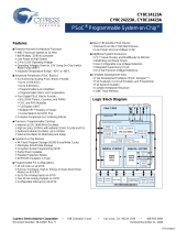
Figure 2-1. WirelessUSB 2-Way System
2.1.1 Radio Channel Management
WirelessUSB uses the unlicensed 2.4 GHz Industrial, Scientific, and Medical (ISM) band for wireless
connectivity. WirelessUSB uses 78 of the available channels and splits the 78 channels into 6 chan-
nel subsets consisting of 13 channels each. The channel subsets are used by each network to mini-
mize the probability of interference from other WirelessUSB systems (see the Channel Selection
Algorithm on page 15 section for more details). A designated channel subset is used during bind
mode (along with an associated pseudo noise code) in order to enable all WirelessUSB devices to
effectively communicate during this procedure.
2.1.2 Pseudo Noise Codes
Pseudo noise codes (PN codes) are the codes used to achieve the special matched filter character-
istics of direct sequence spread spectrum (DSSS) communication. Certain codes referred to as ‘mul-
tiplicative codes’ are used for WirelessUSB 2-way communication. These codes have minimal cross-
correlation properties, meaning they are less susceptible to interference caused by overlapping
transmissions on the same channel. The length of the PN code results in different communication
characteristics. Higher data rates are achieved with 32-chips/bit PN codes, while 64-chips/bit PN
codes allow a longer range. The number of frequency/code pairs is large enough to comfortably
Host PC
or Laptop
WirelessUSB
Keyboard
(Transceiver)
WirelessUSB
Mouse
(Transceiver)
WirelessUSB-LS
Bridge
(Transceiver)
USB
-
[+] Feedback

14 CY4672 Reference Design Guide, Document # 001-16968 Revision **
WirelessUSB™ Protocol 2.2
accommodate hundreds of WirelessUSB devices in the same space. Each bridge/HID pair must use
the same PN code and channel in order to communicate with each other.
2.1.3 Chip Error Correction
In the presence of interference (or near the limits of range), the transmitted PN code will often be
received with some PN code chips corrupted. DSSS receivers use a data correlator to decode the
incoming data stream. WirelessUSB LP supports a separate start of packet (SOP) and data thresh-
old. The RDK uses an SOP threshold of ‘4’. The data threshold is set to the default value of ‘4’.
2.1.4 Automatic Acknowledgment (AutoACK)
The WirelessUSB LP radio contains an automatic acknowledgment feature that allows it to automat-
ically send an ACK to any valid packet that is received. The WirelessUSB LP radio also uses the
concept of transactions to allow the radio in the HID to automatically power down after transmitting a
packet and receiving an AutoACK instead of waiting for the firmware to power the radio down. This
conserves power and reduces the firmware complexity of WirelessUSB applications.
2.1.5 Network ID
The network ID contains the parameters for the channel selection algorithm as well as the PN code
to be used. HIDs retrieve the network ID information from the bridge during the bind procedure. A
special network ID is reserved for bind mode, known as the bind ID. The bind ID gives a common
channel subset so that any two devices can communicate with each other during bind mode. The
network ID is composed of the following fields:
PIN This is a random number between 2–5 that defines the channel subset and is
used in the channel selection algorithm.
Base Channel This is the first channel to be used in the channel selection algorithm, that deter-
mines which channels are contained in the channel subset.
PN Code This is used as an index to select one of 10 used SOP PN codes, as noted in the
radio driver document.
CRC Seed This 8-bit value is used for the CRC calculation, that further diversifies transmis-
sions from different networks. All packets sent between non-bound devices use
the default CRC seed of 0x0000. All packets sent between bound devices use a
CRC seed that is common to all devices bound to a particular bridge or network
but unique from network to network.
2.1.6 Manufacturing ID
Each WirelessUSB radio contains a 4-byte manufacturing ID (MID), that has been laser fused into
the device during manufacturing. The bridge uses its MID to help randomize channel subsets, PN
codes and network CRC seeds. The bridge sends its MID to the HIDs when binding. The HID then
stores the bridge’s MID in non-volatile memory after binding. The HID sends the bridge’s MID as part
of the connect request packet, allowing the bridge to verify the identity of the HID when establishing
a connection.
Both the bridge and the HID use the bridge’s MID as to generate the device network ID components.
The following equations ensure that each network will have a unique set of network ID components:
PN Code = [(mid_1 << 2) + mid_2 + mid_3] mod 10
Base Channel = [(mid_2 >> 2) – (mid_1 << 5) + mid_3] mod 78
PIN = [(((mid_1 -mid_2) & PIN_MASK) + MIN_PIN)] mod 78
CRC Seed = ((mid_2 >> 6)) + mid_1 + mid_3 if=0 then Seed = 1
[+] Feedback

CY4672 Reference Design Guide, Document # 001-16968 Revision ** 15
WirelessUSB™ Protocol 2.2
2.1.7 Channel Selection Algorithm
The channel selection algorithm produces a subset containing 13 of the possible 78 channels. The
channel selection algorithm is based on the network ID, with each channel in the subset being six
megahertz from the nearest neighboring channels in the subset. This algorithm reduces the possibil-
ity of multiple bridges selecting the same channels in the same order at the same time.
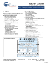
2.2 Protocol Modes
Figure 2-2. Protocol Master
POR
Ping
Mode
Data
Mode
Manual
Bind Mode
Connected Data
KISSBind
Ping
Ping for other networks,
sample the background
RSSI
Bind channel
and PN code
Connected channel and
PN Code
Background RSSI or Link
quality exceeded
[+] Feedback

16 CY4672 Reference Design Guide, Document # 001-16968 Revision **
WirelessUSB™ Protocol 2.2
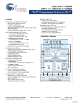
Figure 2-3. Protocol Slave
2.2.1 Ping Mode (Bridge Only)
Ping mode is used by the bridge to find an available channel; channels are unavailable if they are
being used by another network with the same PN code, or if there is excessive noise on the channel.
The bridge first listens for activity on the selected channel. If the channel is inactive the bridge alter-
nately transmits ping packets and listens for ping response packets for a defined* period of time.
During ping mode the bridge also checks the Receive Signal Strength Indicator (RSSI) of the radio in
order to determine if a non-WirelessUSB device is using this channel (or a WirelessUSB device on
the same channel using a different PN code). If a ping response is received, indicating that another
bridge is using this channel the bridge selects the next channel using the channel selection algorithm
and repeats this procedure. The bridge also selects another channel using the channel selection
algorithm if RSSI is high; this indicates that there are other RF sources on the channel. If a ping
response is not received and RSSI is low, the bridge assumes the channel is available and moves to
data mode. Bridges send ping response packets in response to all received ping packets if the
bridge is in data mode. HIDs never respond to ping packets.
[*The timeout value is configurable using the PING_NUM_RSSI define.]
POR
Idle
Mode
Bind
Mode
Data
Mode
Reconnect
Mode
Bound
UnBound,
KISSBind disabled
Wait for
user Bind
event
KISSBind
Mode
UnBound,
KISSBind enabled
Bind fails
Lost
connection
with bridge
Bridge
found
Search for bridge
and sleep if
necessary
Sleep when no data
to be sent
[+] Feedback

CY4672 Reference Design Guide, Document # 001-16968 Revision ** 17
WirelessUSB™ Protocol 2.2
2.2.2 Idle Mode (HID only)
The HID enters this mode after a power on reset before it has had any communication with the RDK
bridge. If the bridge’s MID is stored in non-volatile memory the HID retrieves the bridge’s MID, calcu-
late the network ID and move to reconnect mode. If the bridge’s MID is not stored in non-volatile
memory the HID waits in idle mode until a user-initiated event causes the HID to enter bind mode.
After a defined period of time in idle mode the HID goes to sleep in order to conserve power. When
the HID wakes up due to a user action, it re-enters Idle mode.
2.2.3 Reconnect Mode (HID only)
Reconnect mode is used by the HID to discover the current channel used by the bridge and to estab-
lish a connection with the bridge. Upon entering reconnect mode the HID uses the network ID to
select a channel using the channel selection algorithm. The HID transmits ‘connect requests’ con-
taining the manufacturing ID of the desired bridge and listens for an AutoACK. If an AutoACK is
received the HID disables the AutoACK and continues to listen for a ‘connect response’. If a bridge
in data mode receives a ‘connect request’ containing its manufacturing ID, it sends a positive ‘con-
nect response’ to the HID. If a HID receives a positive ‘connect response’ it moves to data mode. If a
HID does not receive a positive ‘connect response’, it selects the next channel using the channel
selection algorithm and repeats the procedure. If the HID does not receive a positive ‘connect
response’ on any of the channels in the subset, it enters goes to sleep in order to conserve power.
When the HID wakes up due to a user action it reenters reconnect mode.
2.2.4 Button Bind Mode
HID
Bind mode allows the HID to retrieve the bridge’s manufacturing ID which is used to calculate the
network ID. Upon entering bind mode the HID sets the current channel and PN code to the channel
and PN code specified in the bind ID. The HID then transmits bind requests and listens for an
AutoACK. If an AutoACK is received, the HID (keeping the AutoACK enabled) continues to listen for
a bind response (containing the bridge’s MID) from the bridge. If a bind response is not received, the
HID moves to the next channel. If a bind response is received, the HID stores the bridge’s MID, cal-
culates the network ID, and moves to reconnect mode. The algorithms used to calculate these fields
are implementation specific and should be the same on the bridge and the HID (both devices use the
bridge’s manufacturing ID to calculate these fields). If a defined* period of time has elapsed while in
bind mode without receiving a bind response, the HID exits bind mode and restores the channel and
PN code settings that were in use prior to entering bind mode. Bind mode should last long enough
for the user to locate and push the button on both the bridge and the HID. A user-initiated event can
cause the HID to enter bind mode from any other mode.
[*The timeout value is configurable using the BIND_RETRY_COUNT define.]
Bridge
Upon entering bind mode the bridge sets the current channel and PN code to the channel and PN
code specified in the bind ID. The bridge listens for a bind request on each channel for approxi-
mately 320 ms before selecting the next channel using the channel selection algorithm. This reduces
the possibility of the bridge not receiving the bind request from the HID in the event of channel inter-
ference. If the bridge receives a bind request from the HID containing a supported device type, it
sends a bind response containing the bridge’s manufacturing ID and then switches to ping mode.
The bridge also switches to ping mode if the defined* time period has elapsed while in bind mode.
The channel selection algorithm uses the bind ID to produce the channel subset for bind mode.
[*The timeout value is configurable using the NUM_CHANNELS_PER_SUBSET define.]
[+] Feedback

18 CY4672 Reference Design Guide, Document # 001-16968 Revision **
WirelessUSB™ Protocol 2.2
2.2.5 Enhanced KISSBind™
KISSBind provides the ability to automatically bind out of the box without any intervention by the
user other than installing the batteries. KISSBind essentially is a bind process while in the data
mode. The bridge goes through the normal process of pinging and then going to the data mode. The
device upon powering up and determining that it is not bound, transmits KISS_BIND_REQ packets
on all channels and PN codes looking for a bridge that has not been bound to that specific device.
The bridge keeps track of which device is connected and only responds with a KISS_BIND_RESP
packet if it is not already bound to that specific device. Once bound, the bridge stores the device
specific state in Flash.
HID
When the HID first powers up it checks the validity of the flash bind parameters. If the bind parame-
ters checksum is not valid then the HID is considered to be un-bound. The HID then transmits KISS-
Bind request packets on all channels and PN codes using a CRC seed of zero in order to locate the
bridge. If an AutoACK is received the HID enters the receive state to listen for a KISSBind response
packet from the bridge. The HID completes the KISSBind process if a KISSBind response packet is
received from the bridge. If, after RX_PACKET_TIMEOUT (ms), the HID does not receive from the
bridge it then resumes the channel/PN code search for the bridge. If the search sequence is unsuc-
cessful after BIND_RETRY_COUNT attempts, then the HID enters a low power state waiting for a
button press or other activity and begin the search process all over.
Bridge
The bridge, upon powering up, enters the ping mode in order to locate a suitable channel/PN code
based on its MID. When the ping mode is complete the bridge then enters the data mode. If a KISS-
Bind Request packet is received, the bridge checks the bind status for the specific device that sent
the KISSBind request (mouse or keyboard) based on the device type in the packet header. If the
specific device has not been bound then the bridge proceeds by sending a KISSBind response
packet and completing the KISSBind process. Once an AutoACK is received from the HID in
response to the KISSBind response, the bridge updates the Flash bind status for the specific device.
[+] Feedback

CY4672 Reference Design Guide, Document # 001-16968 Revision ** 19
WirelessUSB™ Protocol 2.2
Figure 2-4. KISSBind Transaction Sequence
Master
Slave
KISSBind Request
Ch N, PN 1
KISSBind Response
Connection
Request
Auto ACK
Auto ACK
R
X
KISSBind Request
Ch N + 1, PN 1
Master is in the
connected state on
Ch N+2 PN 3
KISSBind Request
Ch N, PN 3
KISSBind Request
Ch N + 1, PN 3
KISSBind Request
Ch N + 2, PN 3
Auto ACK
Master responds
only if a device of
this type is not
already bound
Master records this
device as being
connected in
FLASH
Data
Auto ACK
Normal traffic
[+] Feedback

20 CY4672 Reference Design Guide, Document # 001-16968 Revision **
WirelessUSB™ Protocol 2.2
2.2.6 Unbind
An ‘unbind’ mechanism allows the bridge and HIDs to return to their default unbind mode as if they
had never bound to any system before.
The bridge dedicates a bind flag to each device type that it supports. A bind flag is a 1-bit field in
Flash. Once the bridge has been bound to an HID by either KISSBind or button bind mechanism, the
bridge sets the corresponding bind flag for that device type and stores the flag in its Flash.
If the bind flag for a particular device type is set, the bridge treats future KISSBind packets from this
device type as nonfunctional packets.
The bridge unbind process clears all bind flags, and the bridge allows devices to KISSBind.
The HID dedicates a byte in its Flash, called SIGNATURE, to indicate whether or not the HID has
bound to a bridge before. The SIGNATURE is set to 0x90 after a successful KISSBind or button
bind. If the SIGNATURE is not set to 0x90, the HID tries to KISSBind to any bridge in the area that
allows the HID to KISSBind. Once the SIGNATURE is set, the HID does not attempt to KISSBind.
Note Once the HID enters unbind mode, power-cycle the HID to exit this mode. Once the bridge is
unbound, the bridge continues to communicate with any HID that already has the bridge MID. In
order to completely unbind the system, the HIDs and bridge must be unbound.
2.2.7 Data Mode
HID
When the HID application has data to send to the bridge the HID transmits a DATA packet and lis-
tens for an AutoACK. If an AutoACK is not received, the HID retransmits the packet. If the HID does
not receive an AutoACK after N DATA_PACKETS_RETRIES of retransmissions of the data packet it
assumes the channel has become unavailable due to excessive interference and moves to recon-
nect mode.
Bridge
Data mode allows application data to be transmitted from the HID to the bridge. The bridge continu-
ously listens for data packets from the HID. When valid data is received from the HID the bridge
sends an ACK to the HID and sends the data to the USB host. If invalid data is received the bridge
ignores the packet and listens for the HID to retransmit the data. The bridge monitors the interfer-
ence level and moves to ping mode if the RSSI interference threshold RSSI_NOISE_THRESHOLD
is reached. This ensures that the bridge is operating on a clean channel.
2.2.8 Back Channel Data Support
Back channel data support provides a mechanism for the host to send data to the device at the
request of the device. The device is responsible for interrogating the bridge for back channel data
either as part of a forward data packet or a simple null packet. The device starts by setting the BCDR
bit in the data header. If the packet is successfully acknowledged by the bridge then the device
inverts the upper byte of the checksum seed and then wait for N ms before trying to receive from the
bridge for M ms. The bridge also inverts the checksum seed and wait N ms before attempting to
transmit to the device. If the bridge has more data to send then it can also set the BCDR flag and can
then expect the device to receive another packet.
[+] Feedback
/