5
Y ale
ale
Y
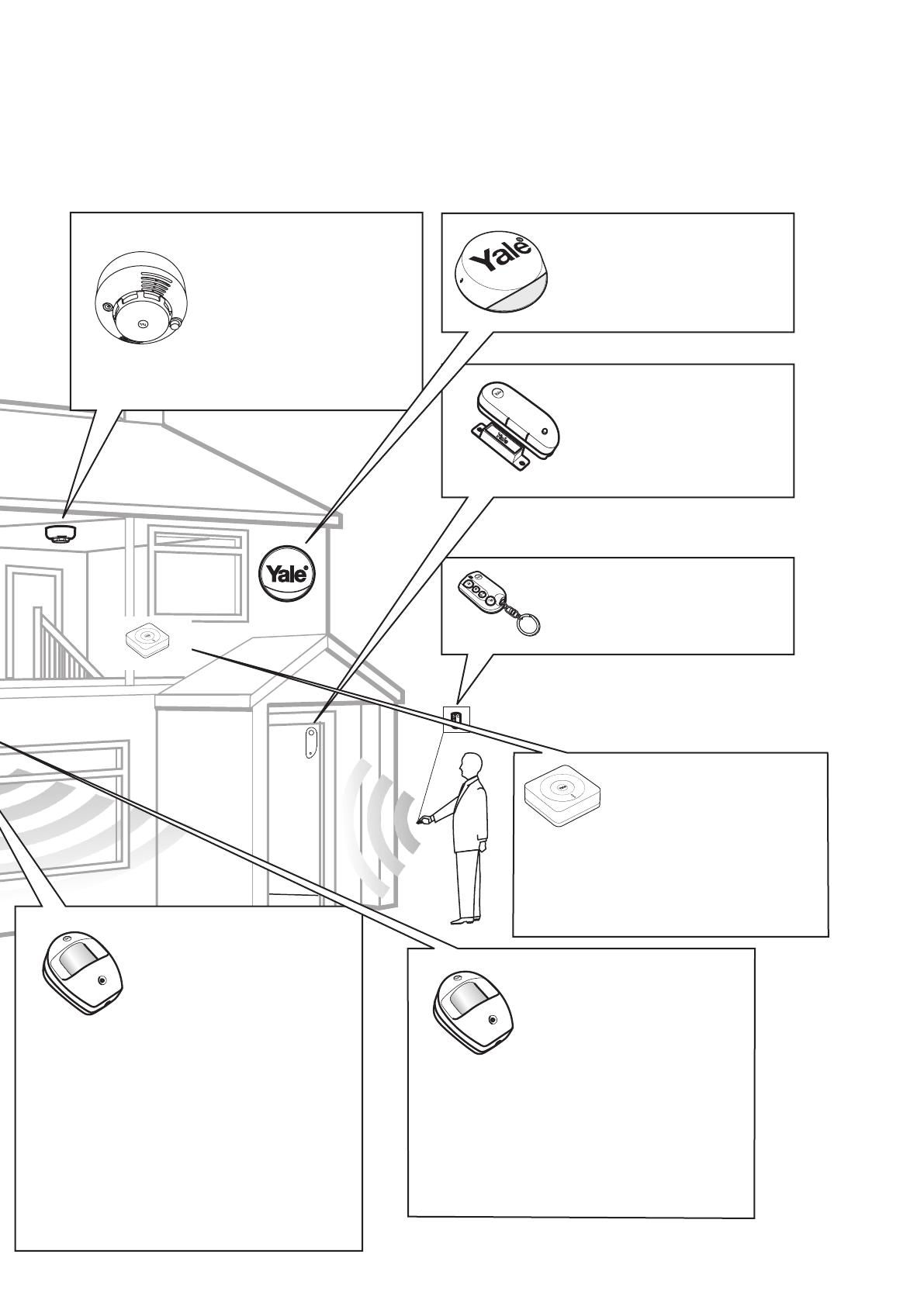
PIR Motion Detectors
• Mount 1.8m - 2.1m above oor level
• Location in a corner will ensure wider room coverage
• Do not mount the PIR where its eld of view will be
obstructed
• Do not point directly at sources of heat e.g. res or
boilers, and do not position directly above radiators
• Avoid mounting the PIR directly facing a window
• Do not point the PIR at a door protected by a Door/
Window Contact
• Pet PIR Motion Detectors
Smoke Detector
External Siren
Mount as high as possible, out of
easy reach.
Door/Window Contact
• Mount as high as possible on
the door or window frame.
Key Fob
• Use inside or outside within a
30m range
Smart Hub 2.0
• Ensure it is hidden from view.
• Access to a mains socket and
broadband internet router is
required.
Introduction
(02)
Thank you for choosing the Yale Smart Home Alarm kit. This simple to install system has
been designed with the user in mind.
All the components are self contained and no connections are needed between the
units. There is no need to damage the home decor, lift carpets or run cables.
You can install up to 20 devices (Max. 6 PIR Cameras) in this system. As well as extra
door/window contacts, PIRs and smoke detectors, you can add keyfob remote controls
and keypads for added control convenience.
There is no need to wire into the mains supply or seek the services of a qualied
electrician. The Smart HUB is powered by an adaptor and all other components are
powered by battery (all batteries included). Batteries will operate for 2 years or more
before they need changing. Regular testing and battery changes (when notied by the
system) will ensure reliability and peace of mind.
The security detectors and external siren are ‘tamper’ protected. Any unauthorised
tampering with these items when the system is armed will result in an alarm.
Display extreme caution when using ladders or steps, please follow manufacturer’s
instructions. Be careful when using hand and power tools and follow the manufacturer’s
guidelines when using them. Take care that the correct tools are used. Wear goggles or
protective clothing where required. The external Siren is extremely loud, please ensure
you replace the cover and retreat to a safe distance before testing.
The dialling facilities must only be used with persons who have consented to being
contacted by the system. The system is not to be used to make 999 emergency calls
directly. Yale do not hold responsibility for any actions taken by emergency services for
incorrect use of the dialling facility.
Special Notes on Compatibility: This alarm system is NOT compatible with HSA6000
series and HSA3000 series accessories. Please note the prex “EF- & SR-” on the front of
the part number to indicate compatibility.
(03)
Learn
Power
LAN
Battery
<On Off>
1
2
3
4
5
6
7
Learn
Power
LAN
Battery
<On Off>
(p. 04-06)
(p. 07)
(p. 08)
(p. 09-10)
(p. 22-24)(p. 11)
(p. 11)
(p. 12-21)
(GB) Step by step index -
Accessories vary depending on kit
Pet PIR Motion Detectors
• Suitable for homes with pets up to 25kg
• For rooms where pets are active and may climb on
furniture, protect the area with a door/window
contact instead to prevent false alarms.
30M
30M
30M
30M
30M
Mount on a ceiling in main access
areas e.g. hallways, top of stairs.


